EP4237675B1 - Procédé de détermination d'un temps d'ouverture d'un injecteur pourvu d'une électrovanne, programme informatique, appareil de commande, moteur à combustion interne et véhicule automobile - Google Patents
Procédé de détermination d'un temps d'ouverture d'un injecteur pourvu d'une électrovanne, programme informatique, appareil de commande, moteur à combustion interne et véhicule automobile Download PDFInfo
- Publication number
- EP4237675B1 EP4237675B1 EP21806159.6A EP21806159A EP4237675B1 EP 4237675 B1 EP4237675 B1 EP 4237675B1 EP 21806159 A EP21806159 A EP 21806159A EP 4237675 B1 EP4237675 B1 EP 4237675B1
- Authority
- EP
- European Patent Office
- Prior art keywords
- time
- armature
- opening
- delay time
- injector
- Prior art date
- Legal status (The legal status is an assumption and is not a legal conclusion. Google has not performed a legal analysis and makes no representation as to the accuracy of the status listed.)
- Active
Links
Images


Classifications
-
- F—MECHANICAL ENGINEERING; LIGHTING; HEATING; WEAPONS; BLASTING
- F02—COMBUSTION ENGINES; HOT-GAS OR COMBUSTION-PRODUCT ENGINE PLANTS
- F02D—CONTROLLING COMBUSTION ENGINES
- F02D41/00—Electrical control of supply of combustible mixture or its constituents
- F02D41/20—Output circuits, e.g. for controlling currents in command coils
- F02D2041/2003—Output circuits, e.g. for controlling currents in command coils using means for creating a boost voltage, i.e. generation or use of a voltage higher than the battery voltage, e.g. to speed up injector opening
-
- F—MECHANICAL ENGINEERING; LIGHTING; HEATING; WEAPONS; BLASTING
- F02—COMBUSTION ENGINES; HOT-GAS OR COMBUSTION-PRODUCT ENGINE PLANTS
- F02D—CONTROLLING COMBUSTION ENGINES
- F02D41/00—Electrical control of supply of combustible mixture or its constituents
- F02D41/20—Output circuits, e.g. for controlling currents in command coils
- F02D2041/202—Output circuits, e.g. for controlling currents in command coils characterised by the control of the circuit
- F02D2041/2055—Output circuits, e.g. for controlling currents in command coils characterised by the control of the circuit with means for determining actual opening or closing time
Definitions
- the invention relates to a method for determining an opening time of an injector with a solenoid valve as well as a computer program, a control unit, an internal combustion engine and a motor vehicle.
- injectors are used to inject fuel directly into a combustion chamber.
- An engine control unit controls the switching valve integrated in the injectors, which causes an injection nozzle to open and close again.
- the amount of fuel injected can be determined by the length of time the switching valve is open.
- solenoid valve injectors When solenoid valve injectors are electrically controlled, it can happen that these valves open and close only with a delay.
- the delay of the individual injectors is subject to tolerances, which means that the injectors have different opening times with the same control time. This results in an undesirable uneven distribution of the fuel mass.
- the WO 2011/012518 A1 describes a method for operating a solenoid valve of an injector.
- the solenoid valve has a valve element with a valve needle and an armature that can be moved by means of an electromagnet.
- the solenoid valve is closed, for example, when de-energized.
- the opening movement of the valve element begins - after the lifting delay - and is limited by a stroke stop.
- the stroke stop is used to determine the end of the valve element's movement.
- the lifting delay can be determined from the start of the activation, the end of the movement and the predetermined movement time ("flight time") of the valve element.
- the lifting delay corresponds to a period of time between the start of the energization of an armature winding ("start of activation") and the lifting of the valve needle from its seat.
- the DE 10 2009 045 469 A1 describes a method for operating a fuel injection valve of an internal combustion engine, in which a first delay time is determined which is a temporal Difference characterized between a time of a first change in a control signal for the valve and a time of a first change in the operating state of the valve corresponding to the first change in the control signal. From the first delay time, at least a second delay time of the valve is deduced, which characterizes a time difference between a time of a second change in the control signal, different from the first change, and a time of a second change in the operating state of the valve corresponding to the second change in the control signal.
- the EP 2 685 074 A1 describes a method for detecting an opening of an electromagnetically actuated fuel injection valve that is actuated by applying a control signal.
- a coil voltage of the fuel injection valve is monitored from the time the injection valve closes and a length of a curve segment with the same sign as the second derivative of the coil voltage is determined. If the length of the curve segment exceeds a calibrated threshold value, it is concluded that the injection valve is open. Further relevant prior art can be found in DE 10 2016 200743 A1 , EP 2 422 067 B1 , DE 10 2009 054588 A1 and EP 2 685 074 A1 .
- the object of the present invention is to provide an improved method for determining an opening time of an injector with a solenoid valve, an improved computer program, an improved control unit, an improved internal combustion engine and an improved motor vehicle.
- the injector with the solenoid valve also called a solenoid valve injector, is used to inject fuel into a combustion chamber of an internal combustion engine.
- the injector is operated electromagnetically.
- the injector has a coil for generating a magnetic field, so that the coil can be used as an electromagnet.
- a biasing element e.g. a spring
- a valve opening is closed, whereby the solenoid valve is forced or held in a closed (valve) position.
- a current can be applied to the coil, which generates the magnetic field.
- the magnetic force exceeds a biasing force of the biasing element.
- the armature arranged on the valve needle can thus be moved by the magnetic force in such a way that the armature carries the valve needle along and moves it against the biasing force. This lifts the valve needle out of the valve seat, releases the valve opening and opens the solenoid valve.
- the current applied to the coil is switched off so that there is no longer a magnetic field. This pushes the valve needle back into the valve seat by the preloading element and blocks the valve opening so that the solenoid valve is back in its closed valve position.
- the opening time of the injector is the time at which the valve needle lifts off the valve seat and exposes the valve opening so that fuel can be injected into the combustion chamber.
- the opening time is the time at which the valve needle initially lifts off the valve seat.
- the method determines the opening time of the injector or solenoid valve. Consequently, a control current is applied to generate the magnetic field of the coil in order to start the opening phase of the solenoid valve.
- the method determines the armature impact time at which the armature strikes the valve needle.
- the armature When the coil is de-energized, the armature is in a rest position in which it rests on a rest seat arranged on the valve needle. When the coil is energized, the armature lifts off the rest seat due to the magnetic force and moves in the direction of an armature stop on the valve needle. The armature is therefore arranged on the valve needle in such a way that it can be moved between the rest seat and the armature stop.
- the armature impact time is therefore the time at which the armature (during the opening phase of the solenoid valve) hits the armature stop of the valve needle. From the armature impact time, an armature free travel can be derived, which corresponds to a distance of movement of the armature from the rest position to the impact on the stroke stop of the valve.
- the method also determines the opening delay time, which corresponds to the time period between the armature impact time and the opening time of the solenoid valve.
- the armature moves in the direction of the armature stop and finally hits it.
- This opening delay time describes the time between the armature impacting the armature stop and the actual opening of the solenoid valve.
- the opening delay time depends largely on the preload force of the preload element in the injector.
- the opening delay time also depends on the magnetic force generated by the energized coil. In other words, the opening delay time depends on an electromagnetic actuator of the injector, which includes the preload element, the coil, the valve needle with the rest seat and the armature stop, and the armature.
- the influence of the preload element can be taken into account using a model, for example. This can be an empirical and/or mathematical model. In other embodiments, the opening delay time can be approximated using a constant time period.
- the opening time of the solenoid valve is determined based on the armature impact time and the opening delay time.
- the opening time can be determined by adding the opening delay time to the armature impact time.
- the method can be used to determine the opening time for a solenoid valve injector relatively easily and precisely.
- the method takes into account the design and/or dimensioning of the elements of the solenoid valve injector, such as the electromagnetic actuator, which can depend on the inductance of the coil (which results from the number of turns of the coil, the dimensions of the coil and possibly a material enclosed by the coil), the armature free travel on the valve needle, etc.
- the time of armature impact can be determined by evaluating a voltage curve.
- the voltage curve refers to the voltage curve applied to the coil.
- the voltage curve can be recorded particularly easily and precisely using appropriate measuring technology. For example, the raw voltage signal can be recorded. Consequently, the time of armature impact can be determined particularly easily and precisely by evaluating the voltage curve.
- the evaluation of the voltage curve can include an evaluation of a first time derivative of the voltage curve.
- a change in the course of the first derivative of the voltage curve can be observed due to a change in speed and a moving mass of the armature and/or the valve needle.
- the armature impact time can thus be determined comparatively precisely and easily by evaluating the first time derivative of the voltage curve.
- the armature impact time can correspond to an extreme value in the first time derivative of the voltage curve.
- “Extreme value” means that the first time derivative has a maximum or a minimum at the armature impact time. The maximum and the minimum are a maximum and a minimum value, respectively.
- the above steps can be used to determine a kink-like gradient drop in the first time derivative of the voltage curve.
- the time of the kink-like gradient drop corresponds to the time of anchor impact.
- the above steps for determining the time of anchor impact result from the assumption that the first derivative of the voltage curve can be approximated using two straight lines, namely a first straight line coming from the start time and a second straight line coming from the end time.
- the gradient of the first straight line is constant until the kink-like gradient drop ("kink") is exceeded during the forward passage.
- "Forward passage" means looking at the first straight line starting from the start time in the direction of the end time.
- the gradient of the second straight line is constant until the kink-like gradient drop is reached during the backward passage.
- “Backward passage” means looking at the second straight line starting from the end time in the direction of the start time.
- periods in the voltage curve in which an armature impact time is implausible can be sorted out in advance. This means that the process can be carried out in a more resource-efficient manner, e.g. on a control unit.
- a difference quotient describes the ratio of the change in a first variable to the change in a second variable, where the first variable depends on the second variable.
- the difference quotient can be used, for example, to determine the slope of a linear function.
- the ratio between a distance between measured values determined at a first point in time and a second point in time and a distance between the first and second points in time can be determined.
- the points in time can be chosen arbitrarily.
- the first point in time can be a current point in time within the underlying evaluation period, where the current point in time is always a current time step of a predetermined time-discrete evaluation grid (calculation grid).
- the evaluation grid determines the measured values at (measurement) points in time that are (essentially) equidistant from one another.
- the second point in time can be constant, e.g. the second point in time can be the start point in time or the end point in time of the evaluation period.
- the term "difference quotient" explicitly includes positive as well as negative values, ie geometrically the slope triangle well known for determining a difference quotient can be oriented in the direction of the x-axis (usually a time axis) or in the opposite direction of the x-axis.
- difference quotient progression refers to the progression of the difference quotient over a specific period of time.
- the first difference quotient progression is formed over the evaluation period and is based on the starting point in time. This means that the difference quotient is determined over the entire evaluation period for each (measurement) point in time of the difference quotients in relation to the starting point in time. The same applies to the second difference quotient progression.
- auxiliary function is formed.
- the auxiliary function is formed in such a way that the first and second difference quotient curves can be directly compared with each other.
- the auxiliary function can comprise a difference between the first difference quotient curve and the second difference quotient curve.
- the auxiliary function can correspond to the difference between the first difference quotient curve and the second difference quotient curve.
- the auxiliary function can, for example, be the second difference quotient curve minus the first difference quotient or vice versa.
- the auxiliary function can be used to evaluate the first and second difference quotient curves.
- the auxiliary function can be used to determine at what point in time the distance between the first difference quotient curve and the second difference quotient curve is greatest. At this point in time, an extreme value is present in the auxiliary function.
- the anchor impact time corresponds to the extreme value in the auxiliary function. In other words, the anchor impact time occurs when the auxiliary function has the extreme value. Depending on how the auxiliary function is formed, the extreme value can be a maximum or minimum value.
- the anchor impact time (based on the first time derivative) can therefore be determined mathematically and therefore easily.
- the anchor impact time corresponds to a peak in the form of an extreme value.
- the voltage curve can include the voltage curve during a boost phase.
- the boost phase is a phase during an opening control of the solenoid valve in which a high voltage, the so-called booster voltage, is applied to the solenoid valve, which can be up to 100 volts, for example.
- the evaluation of the voltage curve can be carried out when the boost phase is present. The method can therefore be carried out in a particularly resource-efficient manner, for example on a control unit.
- the opening delay time can be determined using a model that simulates an operating behavior, in particular an opening behavior and a closing behavior, of the solenoid valve.
- the opening behavior depends (among other things) on the electromagnetic actuator of the injector and significantly on the preload element of the electromagnetic actuator.
- the closing behavior also depends accordingly. There is therefore a strong correlation between the opening behavior and the closing behavior.
- the opening behavior of the solenoid valve can thus be deduced from the closing behavior of the solenoid valve. Since the closing behavior can be determined relatively easily using known methods and the opening behavior has a strong correlation with the closing behavior, the opening delay time can be determined particularly easily using the operating behavior model mentioned above.
- the opening delay time can be determined as a function of a closing delay time of the injector. In other words, the opening delay time can be determined based on the closing delay time.
- the closing delay time is the time between the current to the coil being switched off and the solenoid valve closing. Since there is a strong correlation between the opening behavior and the closing behavior of the solenoid valve, the opening delay time also correlates strongly with the closing delay time.
- the opening delay time may be determined using an opening delay time model.
- the above performance model may include the opening delay time model.
- the above performance model may be the opening delay time model.
- the opening delay time model can be, for example, a characteristic curve or a characteristic map.
- the opening delay time model is constructed in such a way that the closing delay time is used as the input variable and the opening delay time for the injector is the output variable.
- an opening delay time characteristic curve can be used by plotting the opening delay time over the closing delay time.
- the closing delay time is generally particularly easy to determine using measurement technology and appropriate evaluation. Consequently, knowing the closing delay time makes it particularly easy to determine the opening delay time using the opening delay time model.
- the opening delay time model can be determined as follows.
- the closing delay time of the injector is determined for an injector over a large number of tests for different actuation times.
- An actuation time is a period of time for which the coil is energized.
- already known methods can be used to determine the closing delay time, such as the evaluation of a second time derivative of the voltage curve on the coil after the actuation current is switched off.
- an average closing delay time for the injector is formed from the test results.
- a preload force indicator (preload element model) for the injector can be derived from the average closing delay time, wherein the preload force indicator corresponds to at least one measure of the preload force of the preload element.
- the opening delay time of the injector is determined for different actuation times using a large number of tests on the test bench and an average opening delay time is formed from this.
- the average closing delay time and the average opening delay time can be compared with the actual flow rate of the injector.
- the actual flow rate depends on the actual closing delay time and the actual opening delay time.
- the relationship between the average opening delay time and the average closing delay time can be adjusted. This relationship can then be stored in the opening delay time model.
- the opening delay time model can thus be used to determine the (average) opening delay time depending on the preload force or the preload force indicator and the (average) closing delay time.
- the procedure for determining the opening delay time model can be performed for different injectors so that the model can represent a large number of injectors.
- the opening delay time may be dependent on the biasing force of the biasing element of the solenoid valve.
- the biasing element urges the solenoid valve into the closed position.
- the prestressing force of the prestressing element can be approximated by a prestressing element model.
- the prestressing force can be determined particularly easily, at least approximately, using the prestressing element model.
- the prestressing element model can be determined mathematically and/or empirically, for example.
- the prestressing element model can be derived from the average closing delay time.
- the prestressing element model is used to determine the opening delay time.
- the prestressing element model makes it particularly easy to take into account the influence of the prestressing element on the opening delay time.
- the opening delay time can be a predetermined constant period of time.
- the predetermined constant period of time can be injector-dependent and determined by preliminary tests on the test bench.
- the predetermined constant period of time can be stored in the control unit for the internal combustion engine. This makes the use of the predetermined period of time as the opening delay time particularly resource-efficient, since no calculations or evaluations (in the control unit) need to be carried out to determine the opening delay time.
- the alternative method is suitable for solenoid valve injectors that are designed without an armature and/or an armature freewheel.
- the opening time corresponds to the time at which the second extreme value in the second derivative is present.
- the relevant second extreme value is the second peak in the double peak structure above.
- the second extreme value corresponds to the second maximum (in time) in the second derivative of the voltage curve during the boost phase.
- the voltage curve on the coil can be recorded using suitable measuring technology. This allows the second derivative to be determined based on the voltage curve. Using the alternative method, it is possible to determine the opening time mathematically and thus precisely by determining the extreme value.
- a second aspect of the invention relates to a computer program which comprises instructions which, when the program is executed by a computer, cause the computer to carry out one of the methods described above.
- the computer program can be stored on an electrical storage medium.
- a third aspect of the invention relates to a control device which is configured to carry out one of the methods described above.
- a fourth aspect of the invention relates to an internal combustion engine.
- the internal combustion engine can have the injector described above and can be controlled via the above control unit.
- the internal combustion engine is set up and designed to carry out one of the methods described above.
- a fifth aspect of the invention relates to a motor vehicle with the control device described above.
- the motor vehicle is set up and designed to carry out one of the methods described above.
- Fig. 1a shows schematically a solenoid valve injector (injector) 100 in a closed valve position and Fig. 1b shows the injector 100 in an open valve position.
- the injector 100 has a solenoid valve which comprises a valve needle 5 and a valve seat 15.
- the injector 100 has an electromagnetic actuator for actuating the solenoid valve which comprises a coil 1, an armature 11 and a biasing element 13.
- the solenoid valve is a normally closed valve. This means that when the coil 1 is not energized, the valve needle 5 is arranged on the valve seat 15 in such a way that an injection opening 17 is closed by the valve needle 5.
- the preloading element 13 is designed to hold the solenoid valve in the closed position. To do this, the preloading element 13 applies a preload force to the valve needle so that the valve needle is moved in the direction of the valve seat 15 and thus in the closing direction.
- the preloading element 13 is designed as a spring.
- the valve needle 5 has a rest seat 7 and an armature stop 9 for the armature 11, between which the armature 11 can be moved.
- the rest seat 7 and the armature stop 9 therefore define an armature stroke or an armature free travel for the armature 11 relative to the valve needle 5.
- the injector 1 also has a stroke stop 3 which limits a stroke of the valve needle 5 (valve stroke). In the closed valve position, the armature 11 sits on the rest seat 7 and in the open valve position, the armature 11 rests on the armature stop 9 and the stroke stop 3.
- the armature 11 can be moved from the rest seat 7 to the armature stop 9 by applying a control current I to the coil 1 by magnetic force.
- the magnetic force holds the armature 11 on the armature stop 9, so that the armature 11 carries the valve needle 5 against the preload force of the preload element 13 and thus lifts the valve needle 5 out of the valve seat 15 until the armature 11 strikes the lift stop 3.
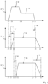
- Fig. 2 shows a control current diagram 20 for a temporal progression of the control current I at the coil 1, an armature stroke diagram 30 for a temporal progression of the armature stroke and a valve stroke diagram 50 for a temporal progression of the valve stroke.
- the armature stroke is the stroke of the armature 5 between the rest seat 7 and the armature stop 9.
- the diagrams 20, 30, 50 show the temporal progressions very schematically.
- the control current diagram 20 shows the application of the control current I at the control time 21 to open the solenoid valve.
- the time profile immediately after the control time 21 has a steep edge, so that the control current I comparatively quickly reaches a corresponding value for a pull-in current phase 22 (pull-in current) at the pull-in time 23.
- the time between the control time 21 and the pull-in time 23 corresponds to a boost phase during an opening phase of the solenoid valve.
- the steep edge makes it possible to achieve a low tolerance and a high reproducibility of the fuel injection quantity.
- the steep edge is achieved by applying a so-called booster voltage to the coil operation until the corresponding current value for the pull-in current phase 22 is reached.
- the control current I is reduced from the pull-in current to a value for a holding current phase 24 (holding current).
- the control current I is switched off and then reaches the value zero at the control end time 29.
- the armature stroke diagram 30 shows the time course of the armature stroke. After the control current I is applied at the control time 21, the armature 5 does not lift off the rest seat 7 until the armature lifting time 31. There is therefore a lifting delay 33 between the application of the control current I and the lifting of the armature 5. At the armature impact time 35, the armature 5 impacts the armature stop 9. The time period between the armature lifting time 31 and the armature impact time 35 corresponds to a flight time 37 of the armature 5.
- the valve lift diagram 50 schematically shows the course of the valve lift of the solenoid valve. This refers to a lift or a deflection of the valve 5 relative to the valve seat 15. Between the armature impact time 35 and an opening time 51 of the solenoid valve there is an opening delay time 52. This is because the armature 11 impacts the armature stop 9 at the armature impact time 35 and carries the valve needle 5 against the preload force of the preload element 13. The armature 11 must primarily overcome the preload force of the preload element 13 until the valve needle 5 is initially lifted off the valve seat 15 at the opening time 51.
- the armature 11 strikes a stroke stop 3, which represents a maximum valve stroke for the valve needle 5 and thus the open valve position.
- a stroke stop 3 represents a maximum valve stroke for the valve needle 5 and thus the open valve position.
- an opening delay time 52 which the valve needle 5 reaches until the maximum valve stroke is reached.
- the solenoid valve is held in this open position for a time period 55 in order to inject fuel into the combustion chamber.
- valve lift diagram 50 there is a closing delay time 61 between the switching off of the control current I at the control time 27 and reaching the closed valve position at the valve closing time 59.
- the previously built-up magnetic field also decreases continuously.
- the magnetic field is then weakened such that the preloading element 13 moves the valve needle 5 in the direction of the valve seat 15 at the time 57 until the solenoid valve is in the closed valve position at the valve closing time 59, i.e. the valve needle 5 closes the injection opening 17.
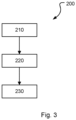
- Fig. 3 shows a method 200 according to an embodiment with which the opening time 51 of the solenoid valve can be determined.
- the armature impact time 35 is determined.
- the armature impact time 35 can be determined by evaluating the voltage applied to the coil 1. The voltage or a voltage signal on the coil 1 can be detected using suitable measuring technology.
- the armature impact time 35 is determined by analyzing the first derivative of the temporal progression of the voltage applied to the coil 1.
- the armature impact time 35 can correspond to the point in time at which an extreme value is present in the first derivative of the voltage progression.
- the relevant extreme value can be the extreme value that first occurs during the boost phase. the derivative.
- the analysis of the voltage curve can be carried out at least or only during the boost phase (which occurs between the control time 21 and the pull-in time 23).
- the opening delay time 52 is determined.
- an opening delay time model can be used, which is described below with reference to Fig. 4 described.
- the closing delay time 61 can be determined by determining the valve closing time 59 and the switch-off time 27.
- the switch-off time 27 can be determined by detecting the switch-off time of the control current I.
- the valve closing time 59 can be determined by known methods. Knowing the valve closing time 59 and the switch-off time 27, the closing delay time 61 can then be determined, which corresponds to the time period between the switch-off time 27 and the valve closing time 59.
- the opening delay time 52 determined in 220 can be a predetermined constant period of time. This approach eliminates the need to determine the closing delay time 61 beforehand, which makes determining the opening delay time 52 particularly easy.
- the opening time 51 is determined based on the armature impact time 35 and the opening delay time 52. According to one embodiment, the opening delay 52 is added to the armature impact time 35 to obtain the opening time 51.
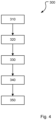
- Fig. 4 shows a method for determining the opening delay time model 300.
- the closing delay time 61 of the injector 100 is determined for different activation times. Tests can be carried out on a test bench for this purpose. An average closing delay time for the injector 100 is formed from the large number of closing delay times 61 for different activation times.
- a preload force indicator (preload element model) for the injector 100 is derived from the average closing delay time, wherein the preload force indicator corresponds to at least a measure of the preload force of the preload element 13.
- the opening delay time 52 of the injector is determined for different activation times on the test bench.
- An average opening delay time for the injector 100 is formed from the multitude of opening delay times 52 for different activation times.
- the average closing delay time and the average opening delay time are compared with an actual flow of the injector 100 in order to adjust or specify a relationship between the average opening delay time and the average closing delay time.
- the relationship between the average opening delay time and the average closing delay time is stored in the opening delay time model.
- the opening delay time model is determined or created.
- the opening delay time model can thus be used to determine the (average) opening delay time as a function of the preload force or the preload force indicator and the (average) closing delay time.
- the method 300 can be carried out for different injectors 100 in order to map a plurality of injectors or closing delay times 61 with the opening delay time model.
- Fig. 5 shows a diagram in which the first derivative of the voltage curve 71 is shown according to a first example.
- the first derivative of the voltage curve 71 is determined based on a raw voltage signal (detected by a voltage sensor) and is therefore very noisy. Consequently, a subsequent evaluation of the raw signal and thus of the first derivative of the voltage curve 71 determined from it can lead to inaccurate results. Therefore, for subsequent evaluations, the raw signal can be smoothed using appropriate methods. For example, a smoothed curve 73 of the first derivative of the voltage curve can be determined from the raw signal using orthogonal polynomials, which is comparatively less noisy and comparatively smooth. Other methods for smoothing the raw voltage signal are also possible. For a subsequent evaluation, e.g. in a control unit, it can be checked whether the supplied voltage signal, i.e. the raw signal, can be used or whether the raw signal or the first temporal derivative must be smoothed beforehand.
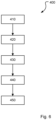
- Fig. 6 shows a method for determining the anchor impact time 400 according to another embodiment for the block 210 from the method 200 according to Figure 4 .
- the start time t A and the end time t E of the evaluation period for evaluating the first time derivative of the voltage curve are determined.
- the first time derivative can be used based on the voltage curve according to a raw signal or based on a smoothed first time derivative of the voltage curve.
- a first difference quotient curve l 1 is formed over the evaluation period based on the initial time t A .
- a second difference quotient curve l 2 is formed over the evaluation period based on the end time t E .
- an auxiliary function a(t) is formed which comprises a quotient of the first difference quotient curve and the second difference quotient curve.
- the auxiliary function a(t) can comprise a difference between the first difference quotient curve and the second difference quotient curve.
- the auxiliary function is evaluated by determining an extreme value in the auxiliary function a(t). The extreme value then corresponds to the anchor impact time.
- Fig. 7a-c show diagrams that serve to derive the method for determining the anchor impact time 400.
- the first derivative based on the raw signal 71 shows a kink-like drop 75.
- the first derivative of the voltage curve 71 can be divided into an area before the kink-like drop 75 (left of the kink-like drop 75) and an area after the kink-like drop 75 (right of the kink-like drop 75). The same applies to the smoothed curve 73 for the first derivative of the voltage signal.
- the first derivative of the voltage curve 71 can be approximated by linear functions.
- the following functions can be used for the left area 77 and the right area 79.
- f 1 t m 1 ⁇ t + n 1 nd .
- f 2 t m 2 ⁇ t + n 2
- f 1 (t) is the first linear function for the left area
- f 2 (t) is the second linear function for the right area
- m 1 and m 2 are the corresponding slopes of the straight lines resulting from the functions
- n 1 and n 2 are the ordinate intercepts (or shift constants) of the straight lines.
- Fig. 7a shows an exemplary approximation function f(t) for an exemplary first derivative of a voltage curve (which differs from the voltage curve of Fig. 5 by the linear functions f 1 (t), f 2 (t).
- the approximation function f(t) is shown for an evaluation period between the (selected) start time t A and the (selected) end time t E.
- kink 81 in the approximation function f(t) occurs at the time t at which the distance between the first difference quotient curve l 1 and the second difference quotient curve l 2 is at its greatest.
- the auxiliary function a(t) can also be formed as the difference between the first difference quotient curve l 1 and the second difference quotient curve l 2 .
- the auxiliary function a(t) can be used to determine a kink-like drop in the first derivative of the voltage curve. Consequently, the time of the kink-like drop and thus the time of anchor impact can also be calculated and thus easily determined.
- Fig. 8a and 8b show an exemplary evaluation of a voltage curve according to a second example.
- Fig. 9a shows a diagram in which a first time derivative for a voltage curve is shown according to a third example. It can be seen that a first kink-like drop 101 is followed by a flattening of the curve 103. The flattening 103 is in turn followed by a second kink-like drop 105.
- Fig. 9b shows a diagram with an auxiliary function a(t) which is used for the value in diagram Fig. 9a shown voltage curve is formed.
- the auxiliary function a(t) has a first peak (maximum) 113, which can be assigned to the first kink-like drop 101, and a second peak 115, which can be assigned to the second kink-like drop 105.
- the armature impact time 35 corresponds to the first peak 113.
- the evaluation period can be selected such that only one peak occurs.
- Fig. 10 shows schematically an exemplary control unit 170 that is set up to carry out the methods/models described above.
- the control unit 170 is arranged in a schematically shown motor vehicle 180 and can control a schematically shown internal combustion engine 179.
- the control unit 170 comprises a processor 172, a memory (electronic storage medium) 174 and an interface 178.
- software (a computer program) 176 is also stored in the memory 174, which is designed to carry out the methods described above.
- the processor 172 is designed to execute program instructions of the software 176.
- the interface 178 is also designed to receive and send data. It can be, for example, an interface to a CAN bus of the motor vehicle 180, via which the control unit 170 receives signals and sends control commands.
Landscapes
- Engineering & Computer Science (AREA)
- Chemical & Material Sciences (AREA)
- Combustion & Propulsion (AREA)
- Mechanical Engineering (AREA)
- General Engineering & Computer Science (AREA)
- Electrical Control Of Air Or Fuel Supplied To Internal-Combustion Engine (AREA)
- Fuel-Injection Apparatus (AREA)
- Magnetically Actuated Valves (AREA)
Claims (15)
- Procédé de détermination d'un temps d'ouverture (51) d'un injecteur (100) pourvu d'une électrovanne au moyen d'un appareil de commande, consistant à :- déterminer un temps de contact d'induit (35) lors duquel un induit (11) de l'électrovanne entre en contact avec un pointeau de vanne (5) de l'électrovanne ;- déterminer un temps de retard d'ouverture (52) de l'injecteur (100) qui correspond à un laps de temps entre le temps de contact d'induit (35) et un temps d'ouverture (51) de l'électrovanne ; et- déterminer un temps d'ouverture (51) de l'injecteur sur la base du temps de contact d'induit (35) et du temps de retard d'ouverture (52).
- Procédé selon la revendication 1, dans lequel le temps de contact d'induit (35) est déterminé par évaluation d'une courbe de tension.
- Procédé selon la revendication 2, dans lequel l'évaluation de la courbe de tension comprend une évaluation d'une dérivée première par rapport au temps de la courbe de tension.
- Procédé selon la revendication 3, dans lequel le temps de contact d'induit (35) correspond à une valeur extrême dans la dérivée première par rapport au temps de la courbe de tension.
- Procédé selon la revendication 3, dans lequel la détermination du temps de contact d'induit consiste en outre à :- déterminer un temps de début et un temps de fin d'une période d'évaluation pour évaluer la dérivée première par rapport au temps de la courbe de tension ;- établir une première courbe de quotient de différence au cours de la période d'évaluation sur la base du temps de début ;- établir une seconde courbe de quotient de différence au cours de la période d'évaluation sur la base du temps de fin ; et- établir une fonction auxiliaire qui comprend un quotient de la première courbe de quotient de différence et de la seconde courbe de quotient de différence ou une différence entre la première courbe de quotient de différence et la seconde courbe de quotient de différence ; et- déterminer une valeur extrême dans la fonction auxiliaire, la valeur extrême correspondant au temps de contact d'induit.
- Procédé selon la revendication 5, dans lequel la fonction auxiliaire (a(t)) est calculée comme suit :


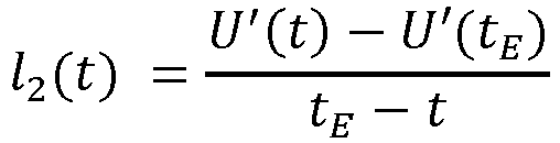 t = temps dans la période d'évaluationtA = temps de début de la période d'évaluationtE = temps de fin de la période d'évaluationU'(t) = dérivée première au temps tU'(tA) = dérivée première au temps de début de la période d'évaluationU'(tE) = dérivée première au temps de fin de la période d'évaluation
 - Procédé selon l'une quelconque des revendications précédentes, dans lequel la courbe de la tension comprend la courbe de la tension pendant une phase d'amplification.
- Procédé selon l'une quelconque des revendications précédentes, dans lequel le temps de retard d'ouverture (52) est déterminé au moyen d'un modèle qui reproduit un comportement de fonctionnement, notamment un comportement d'ouverture et un comportement de fermeture, de l'électrovanne.
- Procédé selon l'une quelconque des revendications précédentes, dans lequel le temps de retard d'ouverture (52) est déterminé en fonction d'un temps de retard de fermeture (61) de l'injecteur (100).
- Procédé selon la revendication 7, dans lequel le temps de retard d'ouverture (52) est déterminé au moyen d'un modèle de temps de retard d'ouverture.
- Procédé selon l'une quelconque des revendications 1 à 5, dans lequel le temps de retard d'ouverture (52) est une durée constante prédéterminée.
- Programme informatique (176) comprenant des instructions qui, lors de l'exécution du programme par un appareil de commande, amènent ce dernier à mettre en œuvre un procédé selon l'une quelconque des revendications précédentes.
- Appareil de commande (170), qui est conçu pour mettre en œuvre le procédé selon l'une quelconque des revendications 1 à 11.
- Moteur à combustion interne comprenant un appareil de commande (179) selon la revendication 13, le moteur à combustion interne (179) étant conçu pour mettre en œuvre un procédé selon l'une quelconque des revendications 1 à 11.
- Véhicule automobile (180) comprenant un moteur à combustion interne (179) selon la revendication 14, le véhicule automobile (180) étant conçu et configuré pour mettre en œuvre un procédé selon l'une quelconque des revendications 1 à 11.
Applications Claiming Priority (2)
| Application Number | Priority Date | Filing Date | Title |
|---|---|---|---|
| DE102020213705.6A DE102020213705A1 (de) | 2020-10-30 | 2020-10-30 | Verfahren zum Ermitteln eines Öffnungszeitpunkts eines Injektors mit einem Magnetventil, Computerprogramm, Steuergerät, Verbrennungskraftmaschine und Kraftfahrzeug |
| PCT/EP2021/079986 WO2022090395A1 (fr) | 2020-10-30 | 2021-10-28 | Procédé de détermination d'un temps d'ouverture d'un injecteur pourvu d'une électrovanne, programme informatique, appareil de commande, moteur à combustion interne et véhicule automobile |
Publications (2)
| Publication Number | Publication Date |
|---|---|
| EP4237675A1 EP4237675A1 (fr) | 2023-09-06 |
| EP4237675B1 true EP4237675B1 (fr) | 2024-12-11 |
Family
ID=78598962
Family Applications (1)
| Application Number | Title | Priority Date | Filing Date |
|---|---|---|---|
| EP21806159.6A Active EP4237675B1 (fr) | 2020-10-30 | 2021-10-28 | Procédé de détermination d'un temps d'ouverture d'un injecteur pourvu d'une électrovanne, programme informatique, appareil de commande, moteur à combustion interne et véhicule automobile |
Country Status (4)
| Country | Link |
|---|---|
| EP (1) | EP4237675B1 (fr) |
| CN (1) | CN116324149B (fr) |
| DE (1) | DE102020213705A1 (fr) |
| WO (1) | WO2022090395A1 (fr) |
Citations (1)
| Publication number | Priority date | Publication date | Assignee | Title |
|---|---|---|---|---|
| EP2685074A1 (fr) * | 2012-07-13 | 2014-01-15 | Delphi Automotive Systems Luxembourg SA | Contrôle dýinjection de carburant pour moteur à combustion interne |
Family Cites Families (14)
| Publication number | Priority date | Publication date | Assignee | Title |
|---|---|---|---|---|
| DE3843138A1 (de) | 1988-12-22 | 1990-06-28 | Bosch Gmbh Robert | Verfahren zur steuerung und erfassung der bewegung eines ankers eines elektromagnetischen schaltorgans |
| DE3942836A1 (de) | 1989-12-23 | 1991-06-27 | Daimler Benz Ag | Verfahren zur bewegungs- und lagezustandserkennung eines durch magnetische wechselwirkung zwischen zwei endpositionen beweglichen bauteiles eines induktiven elektrischen verbrauchers |
| JP4196895B2 (ja) * | 2004-07-12 | 2008-12-17 | 株式会社デンソー | 燃料噴射装置 |
| DE102005015101B4 (de) * | 2005-04-01 | 2014-10-30 | Robert Bosch Gmbh | Verfahren zur Bestimmung der Anschaltzeit eines Magnetventils in einem hydraulischen System |
| DE102009002593A1 (de) * | 2009-04-23 | 2010-10-28 | Robert Bosch Gmbh | Verfahren und Steuergerät zum Betreiben eines aktorbetätigten Ventils |
| DE102009026930A1 (de) * | 2009-06-15 | 2010-12-16 | Robert Bosch Gmbh | Bestimmung der Abhebeverzögerung eines Magnetventils |
| DE102009028048A1 (de) | 2009-07-28 | 2011-02-03 | Robert Bosch Gmbh | Verfahren zum Betreiben eines Magnetventils, insbesondere Einspritzventils einer Kraftstoffeinspritzanlage |
| DE102009045469A1 (de) | 2009-10-08 | 2011-04-14 | Robert Bosch Gmbh | Verfahren und Steuergerät zum Betreiben eines Ventils |
| DE102009054588A1 (de) * | 2009-12-14 | 2011-06-16 | Robert Bosch Gmbh | Verfahren und Steuergerät zum Betreiben eines Ventils |
| DE102010063099A1 (de) | 2010-12-15 | 2012-06-21 | Robert Bosch Gmbh | Verfahren zum Betreiben einer Kraftstoffeinspitzanlage einer Brennkraftmaschine |
| DE102014206430B4 (de) * | 2014-04-03 | 2016-04-14 | Continental Automotive Gmbh | Verfahren und Steuereinheit zur Detektion des Öffnungsbeginnes einer Düsennadel |
| DE102016200743A1 (de) | 2016-01-20 | 2017-07-20 | Robert Bosch Gmbh | Verfahren zur Bestimmung einer Öffnungsverzugsdauer eines Kraftstoffinjektors |
| DE102016200836A1 (de) | 2016-01-21 | 2017-07-27 | Robert Bosch Gmbh | Verfahren zur Regelung eines Magnetventil-Injektors |
| DE102017214712A1 (de) | 2017-08-23 | 2019-02-28 | Robert Bosch Gmbh | Verfahren zur Adaption eines Öffnungsverzugs und eines Schließverzugs eines Dosierventils |
-
2020
- 2020-10-30 DE DE102020213705.6A patent/DE102020213705A1/de active Pending
-
2021
- 2021-10-28 CN CN202180063823.7A patent/CN116324149B/zh active Active
- 2021-10-28 WO PCT/EP2021/079986 patent/WO2022090395A1/fr not_active Ceased
- 2021-10-28 EP EP21806159.6A patent/EP4237675B1/fr active Active
Patent Citations (1)
| Publication number | Priority date | Publication date | Assignee | Title |
|---|---|---|---|---|
| EP2685074A1 (fr) * | 2012-07-13 | 2014-01-15 | Delphi Automotive Systems Luxembourg SA | Contrôle dýinjection de carburant pour moteur à combustion interne |
Also Published As
| Publication number | Publication date |
|---|---|
| CN116324149B (zh) | 2025-04-29 |
| EP4237675A1 (fr) | 2023-09-06 |
| CN116324149A (zh) | 2023-06-23 |
| DE102020213705A1 (de) | 2022-05-05 |
| WO2022090395A1 (fr) | 2022-05-05 |
Similar Documents
| Publication | Publication Date | Title |
|---|---|---|
| DE102011005672B4 (de) | Verfahren, Vorrichtung und Computerprogramm zur elektrischen Ansteuerung eines Aktuators zur Bestimmung des Zeitpunkts eines Ankeranschlags | |
| EP2707587B1 (fr) | Procédé et dispositif de détection du moment de fermeture d'une soupape commande par bobine | |
| DE102010063009B4 (de) | Verfahren und Vorrichtung zur Charakterisierung einer Bewegung eines Kraftstoffinjektors mittels Erfassung und Auswertung einer magnetischen Hysteresekurve | |
| EP2449238B1 (fr) | Appareil et procédé de commande d'un moteur à combustion interne | |
| DE102015206729B4 (de) | Verfahren zum Steuern eines Kraftstoffeinspritz-Magnetventils und entsprechendes Motorsteuergerät | |
| DE102010041320B4 (de) | Bestimmung des Schließzeitpunkts eines Steuerventils eines indirekt angetriebenen Kraftstoffinjektors | |
| DE102010041880B4 (de) | Ermitteln der ballistischen Flugbahn eines elektromagnetisch angetriebenen Ankers eines Spulenaktuators | |
| EP2386021A1 (fr) | Procédé permettant de faire fonctionner un système d'injection de carburant | |
| WO2012159877A2 (fr) | Détermination du comportement d'ouverture standard d'un injecteur de carburant sur la base d'un comportement d'ouverture de test sous l'influence d'une impulsion de test à tension constante | |
| EP2459860B1 (fr) | Procede de fonctionnement d'une soupape magnetique, en particulier d'une soupape d'injection d'une installation d'injection de carburant | |
| DE102009047453A1 (de) | Verfahren zum Betreiben eines Magnetventils, insbesondere Einspritzventils einer Kraftstoffeinspritzanlage | |
| DE19834405B4 (de) | Verfahren zur Schätzung eines Nadelhubs eines Magnetventils | |
| EP1671024A2 (fr) | Procede de regulation d'une electrovanne | |
| DE102011007579B4 (de) | Verfahren zum Betreiben eines Einspritzventils | |
| EP4237675B1 (fr) | Procédé de détermination d'un temps d'ouverture d'un injecteur pourvu d'une électrovanne, programme informatique, appareil de commande, moteur à combustion interne et véhicule automobile | |
| EP4237674B1 (fr) | Procédé de détermination d'un temps de fermeture d'un injecteur pourvu d'une électrovanne, programme informatique, appareil de commande, moteur à combustion interne et véhicule automobile | |
| DE102022209304A1 (de) | Verfahren zur Ansteuerung eines elektromagnetisch ansteuerbaren Gasventils, Steuergerät, Computerprogramm und Computerprogrammprodukt | |
| WO2011082902A1 (fr) | Procédé et dispositif de commande pour faire fonctionner une soupape | |
| WO2018065471A1 (fr) | Fonctionnement d'un injecteur de carburant avec butée hydraulique en présence d'une pression de carburant réduite | |
| DE102021104645A1 (de) | Verfahren zur prüfung der wiederholbarkeit der einspritzung in einen elektromagnetischen kraftstoffinjektor und entsprechender prüfstand | |
| WO2011082901A1 (fr) | Procédé et dispositif de commande pour faire fonctionner une soupape | |
| DE102017204849B3 (de) | Verfahren zum Erkennen einer Veränderung eines zumindest einen Teil eines Gesamtluftspaltes bildenden Arbeitsweges eines Magnetankers eines Kraftstoffeinspritzventils | |
| DE102017204855B3 (de) | Verfahren zum Erkennen einer Veränderung eines zumindest einen Teil eines Gesamtluftspaltes bildenden Arbeitsweges eines Magnetankers eines Kraftstoffeinspritzventils | |
| DE102004063295A1 (de) | Verfahren und Vorrichtung zum Steuern eines Einspritzventils | |
| DE102009044965A1 (de) | Verfahren zum Kontrollieren des Betriebs einer Enspritzdüse |
Legal Events
| Date | Code | Title | Description |
|---|---|---|---|
| STAA | Information on the status of an ep patent application or granted ep patent |
Free format text: STATUS: UNKNOWN |
|
| STAA | Information on the status of an ep patent application or granted ep patent |
Free format text: STATUS: THE INTERNATIONAL PUBLICATION HAS BEEN MADE |
|
| PUAI | Public reference made under article 153(3) epc to a published international application that has entered the european phase |
Free format text: ORIGINAL CODE: 0009012 |
|
| STAA | Information on the status of an ep patent application or granted ep patent |
Free format text: STATUS: REQUEST FOR EXAMINATION WAS MADE |
|
| 17P | Request for examination filed |
Effective date: 20230530 |
|
| AK | Designated contracting states |
Kind code of ref document: A1 Designated state(s): AL AT BE BG CH CY CZ DE DK EE ES FI FR GB GR HR HU IE IS IT LI LT LU LV MC MK MT NL NO PL PT RO RS SE SI SK SM TR |
|
| DAV | Request for validation of the european patent (deleted) | ||
| DAX | Request for extension of the european patent (deleted) | ||
| GRAP | Despatch of communication of intention to grant a patent |
Free format text: ORIGINAL CODE: EPIDOSNIGR1 |
|
| STAA | Information on the status of an ep patent application or granted ep patent |
Free format text: STATUS: GRANT OF PATENT IS INTENDED |
|
| INTG | Intention to grant announced |
Effective date: 20240626 |
|
| GRAS | Grant fee paid |
Free format text: ORIGINAL CODE: EPIDOSNIGR3 |
|
| GRAA | (expected) grant |
Free format text: ORIGINAL CODE: 0009210 |
|
| STAA | Information on the status of an ep patent application or granted ep patent |
Free format text: STATUS: THE PATENT HAS BEEN GRANTED |
|
| AK | Designated contracting states |
Kind code of ref document: B1 Designated state(s): AL AT BE BG CH CY CZ DE DK EE ES FI FR GB GR HR HU IE IS IT LI LT LU LV MC MK MT NL NO PL PT RO RS SE SI SK SM TR |
|
| REG | Reference to a national code |
Ref country code: GB Ref legal event code: FG4D Free format text: NOT ENGLISH |
|
| REG | Reference to a national code |
Ref country code: CH Ref legal event code: EP |
|
| P01 | Opt-out of the competence of the unified patent court (upc) registered |
Free format text: CASE NUMBER: APP_60659/2024 Effective date: 20241111 |
|
| REG | Reference to a national code |
Ref country code: IE Ref legal event code: FG4D Free format text: LANGUAGE OF EP DOCUMENT: GERMAN |
|
| REG | Reference to a national code |
Ref country code: DE Ref legal event code: R096 Ref document number: 502021006111 Country of ref document: DE |
|
| REG | Reference to a national code |
Ref country code: LT Ref legal event code: MG9D |
|
| PG25 | Lapsed in a contracting state [announced via postgrant information from national office to epo] |
Ref country code: HR Free format text: LAPSE BECAUSE OF FAILURE TO SUBMIT A TRANSLATION OF THE DESCRIPTION OR TO PAY THE FEE WITHIN THE PRESCRIBED TIME-LIMIT Effective date: 20241211 |
|
| PG25 | Lapsed in a contracting state [announced via postgrant information from national office to epo] |
Ref country code: FI Free format text: LAPSE BECAUSE OF FAILURE TO SUBMIT A TRANSLATION OF THE DESCRIPTION OR TO PAY THE FEE WITHIN THE PRESCRIBED TIME-LIMIT Effective date: 20241211 |
|
| PG25 | Lapsed in a contracting state [announced via postgrant information from national office to epo] |
Ref country code: BG Free format text: LAPSE BECAUSE OF FAILURE TO SUBMIT A TRANSLATION OF THE DESCRIPTION OR TO PAY THE FEE WITHIN THE PRESCRIBED TIME-LIMIT Effective date: 20241211 |
|
| REG | Reference to a national code |
Ref country code: NL Ref legal event code: MP Effective date: 20241211 |
|
| PG25 | Lapsed in a contracting state [announced via postgrant information from national office to epo] |
Ref country code: ES Free format text: LAPSE BECAUSE OF FAILURE TO SUBMIT A TRANSLATION OF THE DESCRIPTION OR TO PAY THE FEE WITHIN THE PRESCRIBED TIME-LIMIT Effective date: 20241211 |
|
| PG25 | Lapsed in a contracting state [announced via postgrant information from national office to epo] |
Ref country code: NO Free format text: LAPSE BECAUSE OF FAILURE TO SUBMIT A TRANSLATION OF THE DESCRIPTION OR TO PAY THE FEE WITHIN THE PRESCRIBED TIME-LIMIT Effective date: 20250311 |
|
| PG25 | Lapsed in a contracting state [announced via postgrant information from national office to epo] |
Ref country code: LV Free format text: LAPSE BECAUSE OF FAILURE TO SUBMIT A TRANSLATION OF THE DESCRIPTION OR TO PAY THE FEE WITHIN THE PRESCRIBED TIME-LIMIT Effective date: 20241211 Ref country code: GR Free format text: LAPSE BECAUSE OF FAILURE TO SUBMIT A TRANSLATION OF THE DESCRIPTION OR TO PAY THE FEE WITHIN THE PRESCRIBED TIME-LIMIT Effective date: 20250312 |
|
| PG25 | Lapsed in a contracting state [announced via postgrant information from national office to epo] |
Ref country code: RS Free format text: LAPSE BECAUSE OF FAILURE TO SUBMIT A TRANSLATION OF THE DESCRIPTION OR TO PAY THE FEE WITHIN THE PRESCRIBED TIME-LIMIT Effective date: 20250311 |
|
| PG25 | Lapsed in a contracting state [announced via postgrant information from national office to epo] |
Ref country code: NL Free format text: LAPSE BECAUSE OF FAILURE TO SUBMIT A TRANSLATION OF THE DESCRIPTION OR TO PAY THE FEE WITHIN THE PRESCRIBED TIME-LIMIT Effective date: 20241211 |
|
| PG25 | Lapsed in a contracting state [announced via postgrant information from national office to epo] |
Ref country code: SM Free format text: LAPSE BECAUSE OF FAILURE TO SUBMIT A TRANSLATION OF THE DESCRIPTION OR TO PAY THE FEE WITHIN THE PRESCRIBED TIME-LIMIT Effective date: 20241211 |
|
| PG25 | Lapsed in a contracting state [announced via postgrant information from national office to epo] |
Ref country code: PL Free format text: LAPSE BECAUSE OF FAILURE TO SUBMIT A TRANSLATION OF THE DESCRIPTION OR TO PAY THE FEE WITHIN THE PRESCRIBED TIME-LIMIT Effective date: 20241211 |
|
| PG25 | Lapsed in a contracting state [announced via postgrant information from national office to epo] |
Ref country code: IS Free format text: LAPSE BECAUSE OF FAILURE TO SUBMIT A TRANSLATION OF THE DESCRIPTION OR TO PAY THE FEE WITHIN THE PRESCRIBED TIME-LIMIT Effective date: 20250411 |
|
| PG25 | Lapsed in a contracting state [announced via postgrant information from national office to epo] |
Ref country code: PT Free format text: LAPSE BECAUSE OF FAILURE TO SUBMIT A TRANSLATION OF THE DESCRIPTION OR TO PAY THE FEE WITHIN THE PRESCRIBED TIME-LIMIT Effective date: 20250411 |
|
| PG25 | Lapsed in a contracting state [announced via postgrant information from national office to epo] |
Ref country code: EE Free format text: LAPSE BECAUSE OF FAILURE TO SUBMIT A TRANSLATION OF THE DESCRIPTION OR TO PAY THE FEE WITHIN THE PRESCRIBED TIME-LIMIT Effective date: 20241211 |
|
| PG25 | Lapsed in a contracting state [announced via postgrant information from national office to epo] |
Ref country code: RO Free format text: LAPSE BECAUSE OF FAILURE TO SUBMIT A TRANSLATION OF THE DESCRIPTION OR TO PAY THE FEE WITHIN THE PRESCRIBED TIME-LIMIT Effective date: 20241211 |
|
| PG25 | Lapsed in a contracting state [announced via postgrant information from national office to epo] |
Ref country code: SK Free format text: LAPSE BECAUSE OF FAILURE TO SUBMIT A TRANSLATION OF THE DESCRIPTION OR TO PAY THE FEE WITHIN THE PRESCRIBED TIME-LIMIT Effective date: 20241211 |
|
| PG25 | Lapsed in a contracting state [announced via postgrant information from national office to epo] |
Ref country code: CZ Free format text: LAPSE BECAUSE OF FAILURE TO SUBMIT A TRANSLATION OF THE DESCRIPTION OR TO PAY THE FEE WITHIN THE PRESCRIBED TIME-LIMIT Effective date: 20241211 |
|
| PG25 | Lapsed in a contracting state [announced via postgrant information from national office to epo] |
Ref country code: IT Free format text: LAPSE BECAUSE OF FAILURE TO SUBMIT A TRANSLATION OF THE DESCRIPTION OR TO PAY THE FEE WITHIN THE PRESCRIBED TIME-LIMIT Effective date: 20241211 |
|
| PG25 | Lapsed in a contracting state [announced via postgrant information from national office to epo] |
Ref country code: SE Free format text: LAPSE BECAUSE OF FAILURE TO SUBMIT A TRANSLATION OF THE DESCRIPTION OR TO PAY THE FEE WITHIN THE PRESCRIBED TIME-LIMIT Effective date: 20241211 |
|
| REG | Reference to a national code |
Ref country code: DE Ref legal event code: R097 Ref document number: 502021006111 Country of ref document: DE |
|
| PG25 | Lapsed in a contracting state [announced via postgrant information from national office to epo] |
Ref country code: DK Free format text: LAPSE BECAUSE OF FAILURE TO SUBMIT A TRANSLATION OF THE DESCRIPTION OR TO PAY THE FEE WITHIN THE PRESCRIBED TIME-LIMIT Effective date: 20241211 |
|
| PLBE | No opposition filed within time limit |
Free format text: ORIGINAL CODE: 0009261 |
|
| STAA | Information on the status of an ep patent application or granted ep patent |
Free format text: STATUS: NO OPPOSITION FILED WITHIN TIME LIMIT |
|
| 26N | No opposition filed |
Effective date: 20250912 |
|
| PGFP | Annual fee paid to national office [announced via postgrant information from national office to epo] |
Ref country code: DE Payment date: 20251031 Year of fee payment: 5 |
|
| PGFP | Annual fee paid to national office [announced via postgrant information from national office to epo] |
Ref country code: GB Payment date: 20251021 Year of fee payment: 5 |
|
| PGFP | Annual fee paid to national office [announced via postgrant information from national office to epo] |
Ref country code: AT Payment date: 20260113 Year of fee payment: 5 |
|
| PGFP | Annual fee paid to national office [announced via postgrant information from national office to epo] |
Ref country code: FR Payment date: 20251027 Year of fee payment: 5 |