EP4238916A1 - Ensemble dévidoir de tuyau - Google Patents
Ensemble dévidoir de tuyau Download PDFInfo
- Publication number
- EP4238916A1 EP4238916A1 EP22160194.1A EP22160194A EP4238916A1 EP 4238916 A1 EP4238916 A1 EP 4238916A1 EP 22160194 A EP22160194 A EP 22160194A EP 4238916 A1 EP4238916 A1 EP 4238916A1
- Authority
- EP
- European Patent Office
- Prior art keywords
- motor
- hose
- back emf
- controller
- control system
- Prior art date
- Legal status (The legal status is an assumption and is not a legal conclusion. Google has not performed a legal analysis and makes no representation as to the accuracy of the status listed.)
- Pending
Links
Images
Classifications
-
- B—PERFORMING OPERATIONS; TRANSPORTING
- B65—CONVEYING; PACKING; STORING; HANDLING THIN OR FILAMENTARY MATERIAL
- B65H—HANDLING THIN OR FILAMENTARY MATERIAL, e.g. SHEETS, WEBS, CABLES
- B65H75/00—Storing webs, tapes, or filamentary material, e.g. on reels
- B65H75/02—Cores, formers, supports, or holders for coiled, wound, or folded material, e.g. reels, spindles, bobbins, cop tubes, cans, mandrels or chucks
- B65H75/34—Cores, formers, supports, or holders for coiled, wound, or folded material, e.g. reels, spindles, bobbins, cop tubes, cans, mandrels or chucks specially adapted or mounted for storing and repeatedly paying-out and re-storing lengths of material provided for particular purposes, e.g. anchored hoses, power cables
- B65H75/38—Cores, formers, supports, or holders for coiled, wound, or folded material, e.g. reels, spindles, bobbins, cop tubes, cans, mandrels or chucks specially adapted or mounted for storing and repeatedly paying-out and re-storing lengths of material provided for particular purposes, e.g. anchored hoses, power cables involving the use of a core or former internal to, and supporting, a stored package of material
- B65H75/44—Constructional details
- B65H75/4481—Arrangements or adaptations for driving the reel or the material
- B65H75/4486—Electric motors
-
- H—ELECTRICITY
- H02—GENERATION; CONVERSION OR DISTRIBUTION OF ELECTRIC POWER
- H02P—CONTROL OR REGULATION OF ELECTRIC MOTORS, ELECTRIC GENERATORS OR DYNAMO-ELECTRIC CONVERTERS; CONTROLLING TRANSFORMERS, REACTORS OR CHOKE COILS
- H02P6/00—Arrangements for controlling synchronous motors or other dynamo-electric motors using electronic commutation dependent on the rotor position; Electronic commutators therefor
- H02P6/14—Electronic commutators
- H02P6/16—Circuit arrangements for detecting position
- H02P6/18—Circuit arrangements for detecting position without separate position detecting elements
- H02P6/182—Circuit arrangements for detecting position without separate position detecting elements using back-emf in windings
-
- B—PERFORMING OPERATIONS; TRANSPORTING
- B65—CONVEYING; PACKING; STORING; HANDLING THIN OR FILAMENTARY MATERIAL
- B65H—HANDLING THIN OR FILAMENTARY MATERIAL, e.g. SHEETS, WEBS, CABLES
- B65H75/00—Storing webs, tapes, or filamentary material, e.g. on reels
- B65H75/02—Cores, formers, supports, or holders for coiled, wound, or folded material, e.g. reels, spindles, bobbins, cop tubes, cans, mandrels or chucks
- B65H75/34—Cores, formers, supports, or holders for coiled, wound, or folded material, e.g. reels, spindles, bobbins, cop tubes, cans, mandrels or chucks specially adapted or mounted for storing and repeatedly paying-out and re-storing lengths of material provided for particular purposes, e.g. anchored hoses, power cables
- B65H75/38—Cores, formers, supports, or holders for coiled, wound, or folded material, e.g. reels, spindles, bobbins, cop tubes, cans, mandrels or chucks specially adapted or mounted for storing and repeatedly paying-out and re-storing lengths of material provided for particular purposes, e.g. anchored hoses, power cables involving the use of a core or former internal to, and supporting, a stored package of material
- B65H75/40—Cores, formers, supports, or holders for coiled, wound, or folded material, e.g. reels, spindles, bobbins, cop tubes, cans, mandrels or chucks specially adapted or mounted for storing and repeatedly paying-out and re-storing lengths of material provided for particular purposes, e.g. anchored hoses, power cables involving the use of a core or former internal to, and supporting, a stored package of material mobile or transportable
-
- B—PERFORMING OPERATIONS; TRANSPORTING
- B65—CONVEYING; PACKING; STORING; HANDLING THIN OR FILAMENTARY MATERIAL
- B65H—HANDLING THIN OR FILAMENTARY MATERIAL, e.g. SHEETS, WEBS, CABLES
- B65H75/00—Storing webs, tapes, or filamentary material, e.g. on reels
- B65H75/02—Cores, formers, supports, or holders for coiled, wound, or folded material, e.g. reels, spindles, bobbins, cop tubes, cans, mandrels or chucks
- B65H75/34—Cores, formers, supports, or holders for coiled, wound, or folded material, e.g. reels, spindles, bobbins, cop tubes, cans, mandrels or chucks specially adapted or mounted for storing and repeatedly paying-out and re-storing lengths of material provided for particular purposes, e.g. anchored hoses, power cables
- B65H75/38—Cores, formers, supports, or holders for coiled, wound, or folded material, e.g. reels, spindles, bobbins, cop tubes, cans, mandrels or chucks specially adapted or mounted for storing and repeatedly paying-out and re-storing lengths of material provided for particular purposes, e.g. anchored hoses, power cables involving the use of a core or former internal to, and supporting, a stored package of material
- B65H75/44—Constructional details
-
- B—PERFORMING OPERATIONS; TRANSPORTING
- B65—CONVEYING; PACKING; STORING; HANDLING THIN OR FILAMENTARY MATERIAL
- B65H—HANDLING THIN OR FILAMENTARY MATERIAL, e.g. SHEETS, WEBS, CABLES
- B65H75/00—Storing webs, tapes, or filamentary material, e.g. on reels
- B65H75/02—Cores, formers, supports, or holders for coiled, wound, or folded material, e.g. reels, spindles, bobbins, cop tubes, cans, mandrels or chucks
- B65H75/34—Cores, formers, supports, or holders for coiled, wound, or folded material, e.g. reels, spindles, bobbins, cop tubes, cans, mandrels or chucks specially adapted or mounted for storing and repeatedly paying-out and re-storing lengths of material provided for particular purposes, e.g. anchored hoses, power cables
- B65H75/38—Cores, formers, supports, or holders for coiled, wound, or folded material, e.g. reels, spindles, bobbins, cop tubes, cans, mandrels or chucks specially adapted or mounted for storing and repeatedly paying-out and re-storing lengths of material provided for particular purposes, e.g. anchored hoses, power cables involving the use of a core or former internal to, and supporting, a stored package of material
- B65H75/44—Constructional details
- B65H75/4481—Arrangements or adaptations for driving the reel or the material
- B65H75/4484—Electronic arrangements or adaptations for controlling the winding or unwinding process, e.g. with sensors
-
- B—PERFORMING OPERATIONS; TRANSPORTING
- B65—CONVEYING; PACKING; STORING; HANDLING THIN OR FILAMENTARY MATERIAL
- B65H—HANDLING THIN OR FILAMENTARY MATERIAL, e.g. SHEETS, WEBS, CABLES
- B65H75/00—Storing webs, tapes, or filamentary material, e.g. on reels
- B65H75/02—Cores, formers, supports, or holders for coiled, wound, or folded material, e.g. reels, spindles, bobbins, cop tubes, cans, mandrels or chucks
- B65H75/34—Cores, formers, supports, or holders for coiled, wound, or folded material, e.g. reels, spindles, bobbins, cop tubes, cans, mandrels or chucks specially adapted or mounted for storing and repeatedly paying-out and re-storing lengths of material provided for particular purposes, e.g. anchored hoses, power cables
- B65H75/38—Cores, formers, supports, or holders for coiled, wound, or folded material, e.g. reels, spindles, bobbins, cop tubes, cans, mandrels or chucks specially adapted or mounted for storing and repeatedly paying-out and re-storing lengths of material provided for particular purposes, e.g. anchored hoses, power cables involving the use of a core or former internal to, and supporting, a stored package of material
- B65H75/44—Constructional details
- B65H75/48—Automatic re-storing devices
-
- H—ELECTRICITY
- H02—GENERATION; CONVERSION OR DISTRIBUTION OF ELECTRIC POWER
- H02P—CONTROL OR REGULATION OF ELECTRIC MOTORS, ELECTRIC GENERATORS OR DYNAMO-ELECTRIC CONVERTERS; CONTROLLING TRANSFORMERS, REACTORS OR CHOKE COILS
- H02P6/00—Arrangements for controlling synchronous motors or other dynamo-electric motors using electronic commutation dependent on the rotor position; Electronic commutators therefor
- H02P6/08—Arrangements for controlling the speed or torque of a single motor
-
- H—ELECTRICITY
- H02—GENERATION; CONVERSION OR DISTRIBUTION OF ELECTRIC POWER
- H02P—CONTROL OR REGULATION OF ELECTRIC MOTORS, ELECTRIC GENERATORS OR DYNAMO-ELECTRIC CONVERTERS; CONTROLLING TRANSFORMERS, REACTORS OR CHOKE COILS
- H02P6/00—Arrangements for controlling synchronous motors or other dynamo-electric motors using electronic commutation dependent on the rotor position; Electronic commutators therefor
- H02P6/14—Electronic commutators
- H02P6/16—Circuit arrangements for detecting position
- H02P6/17—Circuit arrangements for detecting position and for generating speed information
-
- B—PERFORMING OPERATIONS; TRANSPORTING
- B65—CONVEYING; PACKING; STORING; HANDLING THIN OR FILAMENTARY MATERIAL
- B65H—HANDLING THIN OR FILAMENTARY MATERIAL, e.g. SHEETS, WEBS, CABLES
- B65H2701/00—Handled material; Storage means
- B65H2701/30—Handled filamentary material
- B65H2701/33—Hollow or hose-like material
Definitions
- the present disclosure relates to a hose reel assembly. More specifically, the present disclosure relates to smooth winding and retraction operation of a hose of the hose reel assembly.
- a hose reel assembly is used to provide a flow of fluid, such as water, in spaces, such as lawns, parks, and the like through a hose.
- the hose reel assembly allows for compact storage of fluid-carrying hoses.
- the hose reel assembly may either be fixed in a permanent location, like wall mounted hose reel assemblies.
- the hose reel assembly may be portable and attached to a truck, a wagon, or a cart.
- the most common styles of hose reel assemblies are spring driven, hand crank, or motor driven.
- the hose may unwind and/or retract with the help of the motor, preferably a DC motor.
- the hose retraction in conventional motor driven hose reel assembly may be unregulated. Spool diameter of the hose reel assembly may increase with each layer of the hose during the hose retraction and the hose retraction speed during the end stage of the hose retraction may invariably increase in particular if the rotational speed is kept constant. Thus, due to the increased speed of the hose retraction, the hose may rip out of the hands of a user holding the hose. Further, a stopper coupled to the hose proximate to the hose end may strike the hose reel assembly with large momentum and may thereby cause damage to the hose reel assembly. Thus, it is desirable to control and thus vary the hose retraction speed.
- the hose retraction speed may be controlled if the unwound hose length is known.
- the unwound hose length may be calculated or detected by detecting the speed of operation of the motor and then integrating the speed of operation of the motor with the runtime of the motor shaft.
- One of the methods used therefor is the measurement and thus exploitation of the so called Back Electro-Motive Force (Back EMF) that is the voltage which is opposite in polarity, created by the rotation of a coil in a magnetic field.
- Back EMF is the voltage generated during the operation of a rotating motor.
- the Back EMF is proportional to the speed of the motor and independent of its load.
- the '689 reference provides a hands-free towel dispenser.
- the towel dispenser includes a housing with a roll of towels inside an interior, a sensor for detecting the presence of an object and generating a signal, a motor driving a dispensing means for dispensing a desired length of towel, a control circuit for receiving the signal from the sensing means and controlling supply of power to the motor driving the dispensing mechanism, and a battery.
- the control circuit receives the signal from the sensor and supplies power from the battery to the motor to drive the dispensing means to dispense the desired length of towel from the roll.
- the control circuit determines the speed of operation of the motor driving the dispensing means by using the Back EMF signals generated by the motor. Thereby the control circuit calculates a the run time the motor should drive the dispensing means to dispense the desired length of towel based on the speed of operation of the motor as determined from the Back EMF signals generated by the motor.
- the control circuit calculates a the run time the motor should drive the dispensing means to dispense the desired length of towel based on the speed of operation of the motor as determined from the Back EMF signals generated by the motor.
- the objective of the present invention is at least partially achieved by a control system for a hose reel assembly.
- the control system includes a motor to drive the hose reel and a power supply unit to supply a voltage to drive the motor.
- the control system further includes a controller for controlling supply of power to the motor.
- the controller stops the supply of power to the motor for a pre-determined time-period and allows the motor to coast.
- the controller measures Back EMF during the pre-determined time-period.
- the control system is characterized in that the controller is configured to determine at least on discrete time instance for measuring the Back EMF.
- the controller further then determines the motor speed based on the measured Back EMF.
- the present disclosure advantageously provides a control system that controls retraction of a hose into a hose box of the hose reel assembly.
- the hose reel assembly may either be fixed in a permanent location, like wall mounted hose reel assemblies.
- the hose reel assembly may be portable and attached to a truck, a wagon, or a cart.
- the controlled retraction prevents an undesired increase in hose retraction speed towards the end of the hose retraction process.
- the control system works on the principal of Back EMF measurement during an inactive phase of the motor. Back EMF measurement is indicative of an unwound hose length of the hose reel assembly.
- the controller of the control system regulates hose retraction speed based on calculated unwound hose length.
- the Back EMF of the motor with the Back EMF being proportional to the motors rotational speed but independent of its load, is possible to maintain constant hose retraction speed. Due to the fact that with each part of the hose that is unwound the overall diameter of the hose reel decreases and thus to unwind the same amount of hose at the same time the hose reel has to turn faster. In reverse conclusion when the hose is wound onto the hose reel the rotational speed of the reel has to decrease during time if the same hose length shall be wound at a same time period as the overall diameter constantly increases.
- the dimensional properties of the hose and hose reel such as for example the overall length of the hose and the dimensions of the reel (thickness of its axis and its width), one also knows how much length of a hose will be retraced and/or unwound with each revolution of the hose reel.
- the controller is configured to determine a first time instant and at least one second time instant for measuring Back EMF during the pre-determined time-period the supply of power to the motor is stopped so that the motor coasts. Thereby the first time instant and the second time instant is different from each other.
- the controller further measures Back EMF at the first time instant and the second time instant and then determines the motor speed based on the measured Back EMF at the first time instant and the second time instant.
- the change in voltage, in particular a gradient change, during the whole period "T" can be estimated and thus used for further calculation.
- the controller is configured to determine a first time instant and at least one second time instant for measuring Back EMF during the pre-determined time-period the supply of power to the motor is stopped so that the motor coasts. Thereby the first time instant and the second time instant is different from each other.
- the controller further measures Back EMF at the first time instant and the second time instant and then determines the motor speed based on the measured Back EMF at the first time instant and the second time instant
- the motor is a DC motor and is powered using Puls-Width-Modulation (PWM).
- PWM Puls-Width-Modulation
- the motor is not supplied with electric power during all time, with the motor ten being in sort of an inactive or passive mode.
- the Back EMF is determined.
- it is determined at every period where the motor is not supplied with electric power.
- the Back EMF is just determined during individual ones of the many periods where the motor is not supplied with electric power.
- the Back EMF is determined only during individual periods of the many periods where the motor is not supplied with electric power it allows for an extension of the time period 'T' at these individual periods. This on the one hand allows for a longer and thus more accurate measurement duration while on the other hand does not significantly influence the overall working performance of the motor.
- the hose reel assembly is either being fixed in a permanent location, preferably being wall mounted, or being portable or being attached to a truck, a wagon or a cart.
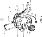
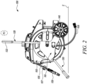
- FIGS. 1 and 2 illustrate a hose reel assembly 100.
- the hose reel assembly 100 of the present disclosure is a hose trolley.
- the hose reel assembly 100 may be in other forms such as, but not limited to, a wall-mounted hose reel assembly.
- the hose trolley 100 is used to house, store, and transport a hose reel 150 (alternately referred to as a hose box 150 ) to different installations, such as lawns, parks, and the like for providing a flow of fluid, such as water.
- the flow of fluid may be provided for firefighting, gardening, surface cleaning and the like activities.
- the hose trolley 100 includes a frame 110 that defines a central axis X-X'.
- the frame 110 may be rigid as well as light weight, depending upon application requirements, user-preference, or other considerations.
- the frame 110 may be manufactured using a metal (preferably aluminum), alloy and the like.
- the frame 110 of the hose trolley 100 includes a handle 120, a support stand 130, one or more wheels 140 and the hose box 150.
- the hose box 150 is housed within the frame 110 along the central axis X-X'.
- the hose box 150 may have a circular, a rectangular or any other shape without limiting the scope of the present disclosure.
- the hose box 150 may be made from metal, fiberglass, or plastic.
- the hose box 150 includes a first part 152 and a second part 154.
- the first part 152 and the second part 154 may be temporarily or permanently attached to each other, such as by fasteners, screws, any suitable means as used or known in the art.
- the hose box 150 may be connected to an external water source via a hose 158. Further, the hose box 150 may supply water for various applications via a hose 156.
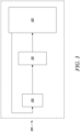
- the hose 156 is retracted into the hose box 150 using a motor 210 (as shown in FIG. 3 ).
- the motor 210 of the present disclosure is a DC motor.
- the operation of the motor 210 is controlled via a controller 220 (as shown in FIG. 3 ).
- the hose 156 is coupled to a stopper 157 at a location proximate to an end of the hose 156 and to a nozzle 159 at the end of the hose 156 for spraying water for various industrial and domestic applications.
- the stopper 157 may serve to restrict or stop the nozzle 159 outside the hose box 150 during the retraction of the hose 156 inside the hose box 150.
- the unwinding is also done via the motor, in particular if the hose is rather non-flexible and/or of increased diameter.
- the unwinding of the hose from the hose reel is done with manual force and the motor controls the unwinding speed or the rotational speed of the hose reel and applies some breaking forces that make the hose reel to decrease its rotating speed.
- the support stand 130 of the frame 110 includes a U-shape grip.
- the support stand 130 may preferably be formed in one piece or alternatively may be formed in two pieces connected to each other by any means know in the art.
- the one or more wheels 140 of the frame 110 are a pair of wheels.
- the pair of wheels 140 may be operationally coupled each on both the sides of the hose trolley 100 to provide sideways fall-over support.
- the pair of wheels 140 may be rotatably coupled with an axle (not shown).
- the wheels 140 may ease support and movement of the hose trolley 100 on the level surface "S" or improve portability between different locations/installations.
- the wheels 140 may be caster wheels 140.
- the caster wheels 140 may help to easily manipulate the hose trolley 100 on the level surface "S".
- the one or more wheels 140 and the axle may be provided with dampers (not shown) to avoid shocks incurred due to movement on any uneven surfaces, among other considerations.
- the one or more wheels 140 may be powered by an electric motor (not shown), or any other powering means.
- the wheels 140 may be removably coupled with the frame 110.
- the wheels 140 may be removable to allow easy servicing, or even replacement. Further, the removable feature of the wheels 140 may make the hose trolley 100 more compact for packaging.
- the handle 120 of the frame 110 includes a grip portion 122.
- the grasping of the grip portion 122 of the handle 120 may provide better hold and safe working, movability of the hose trolley 100 between locations.
- the grip portion 122 may be defined as an inverted U-shaped portion of the handle 120.
- the material used for the grip portion 122 may preferably be, but need not necessarily, PVC or nitrile rubber, or any other plastic or polymer to suit application needs.
- the handle 120 of the hose trolley 100 may be pivotably coupled to the frame 110.
- the pivotable nature of the handle 120 may improve the ergonomics of the hose trolley 100.
- the pivotable handle 120 may also make the hose trolley 100 more compact for packaging, storage, and travel.
- the handle 120 may include a locking mechanism to lock the handle 120 in the pivotable position.
- the locking mechanism may provide a safe and trouble-free operation by disallowing any accidental movement of the pivotable handle 120.
- the locking mechanism may be lever such as a ring-shaped lever to allow easy locking/unlocking of the handle 120.
- the handle 120 may be telescopic.
- the telescopic nature of the handle 120 may further improve the ergonomics of the hose trolley 100. The user may adjust the height of the handle 120 to a comfortable position and easily hold or maneuver the hose trolley 100 on the level surface "S".
- the hose trolley 100 with its construction features as discussed above defines a driving position "P1" (as shown in FIG. 1 ) and an operating position “P2" (as shown in FIG. 2 ).
- the driving position "P1” the hose trolley 100 is supported on the level surface "S" by the one or more wheels 140 and is movable on the level surface "S".
- the support stand 130 does not contact the level surface "S” in the driving position of the hose trolley 100.
- the hose trolley 100 may be easily maneuvered on the level surface "S", by engagement with the handle 120, in the driving position with the help of the one or more wheels 140.
- the hose trolley 100 In the operating position "P2", the hose trolley 100 is supported on the level surface "S” by the support stand 130 and the one or more wheels 140.
- the motor 210 retracts (or even in some embodiments unwinds) the hose 156 as per the requirement.
- the motor 210 derives the power for its operation from a power supply unit 230.
- the power supply unit 230 may be a battery that supplies a voltage "V1" to operate or drive the motor 210.
- the power supply unit 230 may be a rechargeable battery.
- the power supply unit 230 may be a single use battery.
- the power supply unit 230 may be coupled to the motor 210 via wires or leads (not shown).
- the power supply unit 230 may selectively supply the voltage "V1" to operate or drive the motor 210 based on an output from the controller 220.
- the controller 220 controls supply of power to the motor 210 based on the hose retraction status of the hose 156. For example, the controller 220 may stop the supply of power to the motor 210 when the hose retraction of the hose 156 is complete. In some embodiments, the controller 220 may identify completion of hose retraction process by overcurrent detection.
- the controller 220 is configured to control or regulate the hose retraction speed of the hose 156.
- the controller 220 is configured to prevent undesired increase in hose retraction speed of the hose 156 towards the end of the hose retraction process.
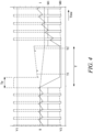
- the controller 220 regulates the hose retraction speed of the hose 156 by measurement of Back EMF during an inactive phase "M0" (as shown in FIG. 4 ) of the motor 210.
- Back EMF measurement allows to determine the rotational speed of the hose reel 150 and integrating the measurement values at different instances of time provides an indication of the length of the hose that is wound onto or unwound from the hose reel assembly 100.
- the hose reel decreases in its overall diameter, and thus to unwind the same amount of hose at the same time the hose reel has to turn faster.
- the rotation of the reel has to decrease during time if the same hose length shall be would at a same time period as the overall diameter constantly increases.
- the knowledge of the unwound hose length of the hose 156 allows the controller 220 to control the motor speed "S" such that the hose retraction speed of the hose 156 is maintained constant.
- the hose retraction speed of the hose 156 may be significantly reduced before the end of the hose retraction process to prevent the stopper 157 from striking hard the hose box 150.
- the controller 220 stops the supply of power to the motor 210 for a pre-determined time-period "T” and allows the motor 210 to coast.
- the controller 220 measures Back EMF during that pre-determined time-period "T”.
- the controller 220 in a first step waits for time-period "Tp" after the motor 210 is switched off.
- Tp time-period
- the controller 220 measures within the time period "T” the Back EMF at least once. It is obvious that the quality of the determination of the Back EMF is increased if several measurements are made at distinct times during the time period "T” and the results averaged.
- the controller 220 determines a first time instant "Tl” and a second time instant "T2" for measuring Back EMF such that the first time instant "Tl” and the second time instant “T2” is different from each other.
- the controller 220 advantageously measures only at the first time instant "Tl” and the second time instant "T2”and not quasi constantly for the full-length of time-period “T” after passing of the time-period "Tp” as this is the case with the state of the art described with the United States patent 6,988,689 .
- the one or more measurement during the inactive phase “M0” also allows to estimate the motor speed "S" during the active phase "M1" of the motor 210.
- the difference in voltage at and the time between two measurements allow to calculate the gradient of the Back EMF from which the decrease in motor speed "S" during inactive phase "M0" of the motor 210 can be derived.
- the terminals of the motor 210 are supplied with the voltages "V1" and "V2" by the power supply 230 to drive it.
- the motor 210 is in its inactive state "M0".
- the difference of the voltages "V1" and “V2" at the terminal of the motor 210 equals the Back EMF.
- the controller 220 further determines the motor speed "S" based on the measured Back EMF at the first time instant "Tl" and the second time instant "T2".
- the motor speed "S” in conjunction with the runtime of the motor shaft (not shown) is utilized by the controller 220 for calculating the unwound hose length of the hose 156.
- the knowledge of the unwound hose length of the hose 156 allows the controller 220 to control the motor speed "S" during the retraction of the hose 156.
- the Back EMF can be used to provide an indication on how much of the hose is already would onto the hose reel and thus how much (length) of the hose is still able to be retracted, but it may also be possible to use the Back EMF already during the unwinding of the hose so that it is also possible to monitor how much (length) of the hose is already wound from the hose reel.
- the motor 210 is a DC motor and is powered using Puls-Width-Modulation (PWM). Using PWM the motor 210 is not supplied with electric power during the inactive/unpowered part of the PWM period.
- PWM Puls-Width-Modulation
- the Back EMF can be determined at every period where the motor 210 is not supplied with electric power or the Back EMF is determined only during individual ones of the many periods where the motor is not supplied with electric power.
- the example shown with Fig. 4 relates to the alternative embodiment where the measurement of Back EMF is done only during individual ones of the many periods where the motor 210 is not supplied with electric power.
- the controller 220 may advantageously introduce dedicated brakes for Back EMF measurement and uses higher pulse width modulation frequencies between these brakes. This may allow the usage of a high overall duty cycle, high and efficient pulse width modulation frequency and still continuous motor speed measurement.
- the present disclosure advantageously provides a control system 200 that controls retraction of the hose 156 into a hose box 150 of the hose reel assembly 100.
- the controlled retraction prevents an unwanted increase in hose retraction speed towards the end of the hose retraction process.
- the control system 200 works on the principal of Back EMF measurement during the inactive phase "M0" of the motor 210. Back EMF measurement is indicative of an unwound hose length of the hose reel assembly 100.
- the controller 220 of the control system 200 regulates hose retraction speed based on calculated unwound hose length.
Landscapes
- Engineering & Computer Science (AREA)
- Power Engineering (AREA)
- Storing, Repeated Paying-Out, And Re-Storing Of Elongated Articles (AREA)
Priority Applications (2)
| Application Number | Priority Date | Filing Date | Title |
|---|---|---|---|
| EP22160194.1A EP4238916A1 (fr) | 2022-03-04 | 2022-03-04 | Ensemble dévidoir de tuyau |
| CN202310226336.9A CN116692604A (zh) | 2022-03-04 | 2023-03-03 | 用于软管卷盘组件的控制系统 |
Applications Claiming Priority (1)
| Application Number | Priority Date | Filing Date | Title |
|---|---|---|---|
| EP22160194.1A EP4238916A1 (fr) | 2022-03-04 | 2022-03-04 | Ensemble dévidoir de tuyau |
Publications (1)
| Publication Number | Publication Date |
|---|---|
| EP4238916A1 true EP4238916A1 (fr) | 2023-09-06 |
Family
ID=80682242
Family Applications (1)
| Application Number | Title | Priority Date | Filing Date |
|---|---|---|---|
| EP22160194.1A Pending EP4238916A1 (fr) | 2022-03-04 | 2022-03-04 | Ensemble dévidoir de tuyau |
Country Status (2)
| Country | Link |
|---|---|
| EP (1) | EP4238916A1 (fr) |
| CN (1) | CN116692604A (fr) |
Citations (7)
| Publication number | Priority date | Publication date | Assignee | Title |
|---|---|---|---|---|
| US3708737A (en) * | 1971-05-19 | 1973-01-02 | California Data Corp | Electric motor speed sensing |
| US3976926A (en) * | 1974-08-05 | 1976-08-24 | Hewlett-Packard Company | Digital DC motor speed control circuit |
| US6988689B2 (en) | 2003-10-10 | 2006-01-24 | Bay West Paper Corporation | Hands-free towel dispenser with EMF controller |
| US7350736B2 (en) * | 2004-07-01 | 2008-04-01 | Great Stuff, Inc. | Systems and methods for controlling spooling of linear material |
| WO2008103630A1 (fr) * | 2007-02-21 | 2008-08-28 | Borgwarner Inc. | Réglage de commutation d'un moteur cc sans balai pour augmenter la vitesse de moteur |
| CN100568706C (zh) * | 2005-11-14 | 2009-12-09 | 萨比股份公司 | 测量感应电动机角速度的方法 |
| US20180162459A1 (en) * | 2016-12-14 | 2018-06-14 | GM Global Technology Operations LLC | Onboard diagnostics of an active air dam assembly |
-
2022
- 2022-03-04 EP EP22160194.1A patent/EP4238916A1/fr active Pending
-
2023
- 2023-03-03 CN CN202310226336.9A patent/CN116692604A/zh active Pending
Patent Citations (7)
| Publication number | Priority date | Publication date | Assignee | Title |
|---|---|---|---|---|
| US3708737A (en) * | 1971-05-19 | 1973-01-02 | California Data Corp | Electric motor speed sensing |
| US3976926A (en) * | 1974-08-05 | 1976-08-24 | Hewlett-Packard Company | Digital DC motor speed control circuit |
| US6988689B2 (en) | 2003-10-10 | 2006-01-24 | Bay West Paper Corporation | Hands-free towel dispenser with EMF controller |
| US7350736B2 (en) * | 2004-07-01 | 2008-04-01 | Great Stuff, Inc. | Systems and methods for controlling spooling of linear material |
| CN100568706C (zh) * | 2005-11-14 | 2009-12-09 | 萨比股份公司 | 测量感应电动机角速度的方法 |
| WO2008103630A1 (fr) * | 2007-02-21 | 2008-08-28 | Borgwarner Inc. | Réglage de commutation d'un moteur cc sans balai pour augmenter la vitesse de moteur |
| US20180162459A1 (en) * | 2016-12-14 | 2018-06-14 | GM Global Technology Operations LLC | Onboard diagnostics of an active air dam assembly |
Non-Patent Citations (1)
| Title |
|---|
| SHAO J ET AL: "Further improvement of direct back EMF detection for sensorless brushless DC (BLDC) motor drives", APPLIED POWER ELECTRONICS CONFERENCE AND EXPOSITION, 2005. APEC 2005. TWENTIETH ANNUAL IEEE AUSTIN, TX, USA 6-10 MARCH 2005, PISCATAWAY, NJ, USA,IEEE, US, vol. 2, 6 March 2005 (2005-03-06), pages 933 - 937Vol.2, XP010809347, ISBN: 978-0-7803-8975-5, DOI: 10.1109/APEC.2005.1453098 * |
Also Published As
| Publication number | Publication date |
|---|---|
| CN116692604A (zh) | 2023-09-05 |
Similar Documents
| Publication | Publication Date | Title |
|---|---|---|
| US11697570B2 (en) | Systems and methods for spooling and unspooling linear material | |
| US10370218B2 (en) | Reel with manually actuated retraction system | |
| AU2005262296B2 (en) | Systems and methods for controlling spooling of linear material | |
| US12414664B2 (en) | Smart nozzle and a surface cleaning device implementing same | |
| JP4139384B2 (ja) | 自動送り/巻戻式電気コードリール | |
| US20040200505A1 (en) | Robot vac with retractable power cord | |
| WO2014170638A1 (fr) | Aspirateur ayant un dispositif de diagnostic | |
| EP4238916A1 (fr) | Ensemble dévidoir de tuyau | |
| CN219429405U (zh) | 软管卷盘组件 | |
| EP4122799B1 (fr) | Chariot de tuyau | |
| TWI921578B (zh) | 軟管推車 | |
| JPH01230324A (ja) | 自走式掃除機 |
Legal Events
| Date | Code | Title | Description |
|---|---|---|---|
| PUAI | Public reference made under article 153(3) epc to a published international application that has entered the european phase |
Free format text: ORIGINAL CODE: 0009012 |
|
| STAA | Information on the status of an ep patent application or granted ep patent |
Free format text: STATUS: THE APPLICATION HAS BEEN PUBLISHED |
|
| AK | Designated contracting states |
Kind code of ref document: A1 Designated state(s): AL AT BE BG CH CY CZ DE DK EE ES FI FR GB GR HR HU IE IS IT LI LT LU LV MC MK MT NL NO PL PT RO RS SE SI SK SM TR |
|
| STAA | Information on the status of an ep patent application or granted ep patent |
Free format text: STATUS: REQUEST FOR EXAMINATION WAS MADE |
|
| 17P | Request for examination filed |
Effective date: 20240301 |
|
| RBV | Designated contracting states (corrected) |
Designated state(s): AL AT BE BG CH CY CZ DE DK EE ES FI FR GB GR HR HU IE IS IT LI LT LU LV MC MK MT NL NO PL PT RO RS SE SI SK SM TR |
|
| STAA | Information on the status of an ep patent application or granted ep patent |
Free format text: STATUS: EXAMINATION IS IN PROGRESS |
|
| 17Q | First examination report despatched |
Effective date: 20250731 |