EP4239320A1 - Dispositif et procédé d'inspection d'une surface intérieure d'un corps creux - Google Patents
Dispositif et procédé d'inspection d'une surface intérieure d'un corps creux Download PDFInfo
- Publication number
- EP4239320A1 EP4239320A1 EP20812395.0A EP20812395A EP4239320A1 EP 4239320 A1 EP4239320 A1 EP 4239320A1 EP 20812395 A EP20812395 A EP 20812395A EP 4239320 A1 EP4239320 A1 EP 4239320A1
- Authority
- EP
- European Patent Office
- Prior art keywords
- plane mirror
- tube
- light
- line
- opening
- Prior art date
- Legal status (The legal status is an assumption and is not a legal conclusion. Google has not performed a legal analysis and makes no representation as to the accuracy of the status listed.)
- Pending
Links
Images


Classifications
-
- G—PHYSICS
- G01—MEASURING; TESTING
- G01N—INVESTIGATING OR ANALYSING MATERIALS BY DETERMINING THEIR CHEMICAL OR PHYSICAL PROPERTIES
- G01N21/00—Investigating or analysing materials by the use of optical means, i.e. using sub-millimetre waves, infrared, visible or ultraviolet light
- G01N21/84—Systems specially adapted for particular applications
- G01N21/88—Investigating the presence of flaws or contamination
- G01N21/95—Investigating the presence of flaws or contamination characterised by the material or shape of the object to be examined
- G01N21/954—Inspecting the inner surface of hollow bodies, e.g. bores
-
- G—PHYSICS
- G01—MEASURING; TESTING
- G01N—INVESTIGATING OR ANALYSING MATERIALS BY DETERMINING THEIR CHEMICAL OR PHYSICAL PROPERTIES
- G01N21/00—Investigating or analysing materials by the use of optical means, i.e. using sub-millimetre waves, infrared, visible or ultraviolet light
- G01N21/84—Systems specially adapted for particular applications
- G01N21/88—Investigating the presence of flaws or contamination
- G01N21/8806—Specially adapted optical and illumination features
-
- G—PHYSICS
- G01—MEASURING; TESTING
- G01N—INVESTIGATING OR ANALYSING MATERIALS BY DETERMINING THEIR CHEMICAL OR PHYSICAL PROPERTIES
- G01N21/00—Investigating or analysing materials by the use of optical means, i.e. using sub-millimetre waves, infrared, visible or ultraviolet light
- G01N21/84—Systems specially adapted for particular applications
- G01N21/88—Investigating the presence of flaws or contamination
- G01N21/8851—Scan or image signal processing specially adapted therefor, e.g. for scan signal adjustment, for detecting different kinds of defects, for compensating for structures, markings, edges
-
- G—PHYSICS
- G01—MEASURING; TESTING
- G01N—INVESTIGATING OR ANALYSING MATERIALS BY DETERMINING THEIR CHEMICAL OR PHYSICAL PROPERTIES
- G01N21/00—Investigating or analysing materials by the use of optical means, i.e. using sub-millimetre waves, infrared, visible or ultraviolet light
- G01N21/84—Systems specially adapted for particular applications
- G01N21/88—Investigating the presence of flaws or contamination
- G01N21/8806—Specially adapted optical and illumination features
- G01N2021/8835—Adjustable illumination, e.g. software adjustable screen
-
- G—PHYSICS
- G01—MEASURING; TESTING
- G01N—INVESTIGATING OR ANALYSING MATERIALS BY DETERMINING THEIR CHEMICAL OR PHYSICAL PROPERTIES
- G01N21/00—Investigating or analysing materials by the use of optical means, i.e. using sub-millimetre waves, infrared, visible or ultraviolet light
- G01N21/84—Systems specially adapted for particular applications
- G01N21/88—Investigating the presence of flaws or contamination
- G01N21/95—Investigating the presence of flaws or contamination characterised by the material or shape of the object to be examined
- G01N2021/9511—Optical elements other than lenses, e.g. mirrors
-
- G—PHYSICS
- G01—MEASURING; TESTING
- G01N—INVESTIGATING OR ANALYSING MATERIALS BY DETERMINING THEIR CHEMICAL OR PHYSICAL PROPERTIES
- G01N2201/00—Features of devices classified in G01N21/00
- G01N2201/06—Illumination; Optics
- G01N2201/061—Sources
- G01N2201/06113—Coherent sources; lasers
-
- G—PHYSICS
- G01—MEASURING; TESTING
- G01N—INVESTIGATING OR ANALYSING MATERIALS BY DETERMINING THEIR CHEMICAL OR PHYSICAL PROPERTIES
- G01N2201/00—Features of devices classified in G01N21/00
- G01N2201/10—Scanning
- G01N2201/104—Mechano-optical scan, i.e. object and beam moving
- G01N2201/1047—Mechano-optical scan, i.e. object and beam moving with rotating optics and moving stage
Definitions
- the present invention relates to devices and methods of inspection of inner surfaces of hollow bodies.
- EP0267705A2 shows a device of inspection of an inner surface of a hollow body comprising an emitter for emitting a line of light onto the inner surface, a receiver for receiving the line of light reflected by the inner surface, optical means for directing the line of light emitted by the emitter towards the inner surface and directing the line of light reflected by the inner surface towards the receiver, and a tube having an upper end and a lower end which is configured for being housed in the hollow body during the inspection.
- the object of the invention is to provide a device and a method of inspection of an inner surface of a hollow body, as defined in the claims.
- One aspect of the invention relates to a device of inspection of an inner surface of a hollow body comprising an emitter for emitting a line of light onto the inner surface, a receiver for receiving the line of light reflected by the inner surface, optical means for directing the line of light emitted by the emitter towards the inner surface and directing the line of light reflected by the inner surface towards the receiver, and a tube having an upper end and a lower end which is configured for being housed in the hollow body during the inspection, and an axial axis extending from the upper end to the lower end.
- the upper end of the tube has a first upper opening which is facing the emitter for the passage of the line of light emitted by the emitter and a second upper opening which is facing the receiver for the passage of the line of light reflected by the inner surface
- the lower end of the tube has a lower opening which during inspection is facing the inner surface for the passage of the line of light emitted by the emitter and of the line of light reflected by the inner surface.
- the optical means comprise at least one upper plane mirror which is arranged inside the upper end of the tube, and first and second lower plane mirrors which are arranged inside the lower end of the tube, the upper plane mirror is facing the first upper opening for reflecting the line of light emitted by the emitter and directing it towards the first lower plane mirror, or is facing the second upper opening for receiving the line of light reflected by the inner surface from the second lower plane mirror and directing it towards the receiver, the first lower plane mirror is facing the lower opening for receiving the line of light emitted by the emitter and directing it onto the inner surface, and the second lower plane mirror is facing the lower opening for reflecting the line of light reflected by the inner surface and directing it towards the receiver.
- Another aspect of the invention relates to a method of inspection of an inner surface of a hollow body using the device described above.
- the method comprises emitting from the emitter a line of light onto the inner surface, generating a vertical translation of the tube with respect to the inner surface of the hollow body, generating a rotation of the tube with respect to the inner surface of the hollow body, capturing in the receiver an image of the line of light reflected by the inner surface, and processing the captured image to obtain the topography of the inner surface.
- the tube of the device has in its interior all the mirrors needed for conducting the light from the emitter to the inner surface of the hollow body, and from the inner surface to the receiver. This simplifies the calibration of the device and the versatility of use of the device for inspecting different hollow bodies, since the position of the mirrors inside the tube is kept fixed regardless of the movements the tube has to make to perform the inspection.
- the tube of the device of EP0267705A2 has optical means for sending light from the emitter and reflecting it towards the receiver outside the tube, which makes it necessary to calibrate the emitter and the receiver every time the device has to be moved to inspect a new hollow body.
- the tube of the device has at its upper end independent openings for emitting the line of light and for receiving the line of light reflected by the inner surface, which prevents the lines of light from going along the same optical path as they travel through the inside of the tube, thus simplifying the optical means needed for performing the inspection, such that only plane mirrors are required for conducting the light.
- EP0267705A2 has a single opening at its upper end for sending and receiving light along one and the same optical path and requires using beam combiners, beam splitters, and mirrors with apertures, complicating the optical assembly and making the device more expensive.
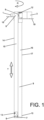
- Figure 1 shows an embodiment of the device of inspection of an inner surface 2 of a hollow body according to the invention.
- the device comprises an emitter 1 for emitting a line of light L1 onto the inner surface 2, a receiver 3 for receiving the line of light L2 reflected by the inner surface 2, optical means for directing the line of light L1 emitted by the emitter 1 towards the inner surface 2 and directing the line of light L2 reflected by the inner surface 2 towards the receiver 3, and a tube 8 having an upper end 9 and a lower end 10 which is configured for being housed in the hollow body during the inspection.
- the tube 8 has an axial axis X extending from the upper end 9 to the lower end 10.
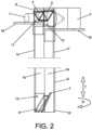
- the axial axis X extends vertically through the center of the tube 8, as shown in Figure 4 .
- the upper end 9 of the tube 8 has a first upper opening 11 which is facing the emitter 1 for the passage of the line of light L1 emitted by the emitter 1 and a second upper opening 12 which is facing the receiver 3 for the passage of the line of light L2 reflected by the inner surface 2.
- the lower end 10 of the tube 8 has a lower opening 13 which during inspection is facing the inner surface 2 for the passage of the line of light L1 emitted by the emitter 1 and of the line of light L2 reflected by the inner surface 2.
- the optical means comprise at least three plane mirrors which are arranged inside the tube 8.
- the optical means comprise at least one upper plane mirror 4 or 5 which is arranged inside the upper end 9 of the tube 8, and first and second lower plane mirrors 6 and 7 which are arranged inside the lower end 10 of the tube 8.
- the upper plane mirror 4 or 5 is facing the first upper opening 11 for reflecting the line of light L1 emitted by the emitter 1 and directing it towards the first lower plane mirror 6, or is facing the second upper opening 12 for receiving the line of light L2 reflected by the inner surface 2 from the second lower plane mirror 7 and directing it towards the receiver 3.
- the first lower plane mirror 6 is facing the lower opening 13 for receiving the line of light L1 emitted by the emitter 1 and directing it onto the inner surface 2.
- the second lower plane mirror 7 is facing the lower opening 13 for reflecting the line of light L2 reflected by the inner surface 2 and directing it towards the receiver 3.
- a single upper plane mirror 4 or 5 which is arranged inside the upper end 9 of the tube 8, and two lower plane mirrors 6 and 7 which are arranged inside the lower end 10 of the tube 8 are used.
- the emitter 1 is arranged parallel to the axial axis X of the tube 8 for directly emitting the line of light L1 in a manner parallel to the axial axis X of the tube 8 through the first opening 11
- the receiver 3 is arranged perpendicular to the axial axis X of the tube 8 for receiving the line of light L2 reflected by the upper plane mirror 5 in a manner perpendicular to the axial axis of the tube 8 through the second opening 12.
- the emitter 1 is arranged perpendicular to the axial axis X of the tube 8 for emitting the line of the light L1 towards the upper plane mirror 4 in a manner perpendicular to the axial axis X of the tube 8 through the first opening 11, and the receiver 3 is arranged parallel to the axial axis X of the tube 8 for directly receiving the line of light L2 reflected by the inner surface 2 in a manner parallel to the axial axis X of the tube 8 (these arrangements are not depicted in the figures).
- the optical means comprise four plane mirrors 4, 5, 6, and 7 which are arranged inside the tube 8.
- the optical means comprise first and second upper plane mirrors 4 and 5 which are arranged inside the upper end 9 of the tube 8, and first and second lower plane mirrors 6 and 7 which are arranged inside the lower end 10 of the tube 8.
- the first upper plane mirror 4 is facing the first upper opening 11 for reflecting the line of light L1 emitted by the emitter 1 and directing it towards the first lower plane mirror 6.
- the second upper plane mirror 5 is facing the second upper opening 12 for receiving the line of light L2 reflected by the inner surface 2 from the second lower plane mirror 7 and directing it towards the receiver 3.
- the first lower plane mirror 6 is facing the lower opening 13 for receiving the line of light L1 reflected by the first upper plane mirror 4 and directing it onto the inner surface 2.
- the second lower plane mirror 7 is facing the lower opening 13 for reflecting the line of light L2 reflected by the inner surface 2 and directing it towards the second upper plane mirror 5.
- the optical means consist of the four plane mirrors 4, 5, 6, and 7 which are arranged inside the tube 8. Accordingly, the tube 8 exclusively has four plane mirrors, and no additional reflective element in the tube 8 is required for conducting the light from the emitter 1 to the receiver 3, which simplifies the manufacture of the tube 8 and reduces the cost of the device.
- the first upper plane mirror 4 is vertically aligned with the first lower plane mirror 6 for defining a first optical axis of the line of light L1 emitted which is parallel to the axial axis X of the tube 8
- the second upper plane mirror 5 is vertically aligned with the second lower plane mirror 7 for defining a second optical axis of the line of light L2 reflected which is parallel to the axial axis X of the tube 8.
- the first optical axis is independent of the second optical axis, such that two independent optical paths are established for emitting the line of light L1 from the emitter 1 to the inner surface 2, and for receiving the line of light L2 reflected by the inner surface 2 in the receiver 3.
- the light of one does not interfere with the other one, so it is not necessary to use complex optical means for conducting the light, where only plane mirrors can be used.
- one and the same optical path is used for sending and receiving light, as in the case of EP0267705A2 , it is necessary to use beam splitters and combiners, and therefore a more powerful emitter 1 so as not to lose light power.
- the first opening 11 is arranged forming a 180° angle with respect to the second opening 12, and the third opening 13 is arranged forming a 90° angle with respect to the first opening 11 and the second opening 12.
- the first opening 11 is diametrically opposite the second opening 12.
- the first upper plane mirror 4 is inclined with respect to the first opening 11 and oriented towards the first lower plane mirror 6,
- the second upper plane mirror 5 is inclined with respect to the second opening 12 and oriented towards the second lower plane mirror 7,
- the first lower plane mirror 6 is inclined with respect to the third opening 13 and oriented towards the first upper plane mirror 4, and the second lower plane mirror 7 is inclined with respect to the third opening 13 and oriented towards the second upper plane mirror 5, and it is also rotated with respect to the first lower plane mirror 6.
- the rotation of the second lower plane mirror 7 depends on the distance between the lower opening 13 of the tube 8 and the inner surface 2 of the hollow body.
- the second lower plane mirror 7 is positioned at the lower end 10 of the tube 8 for directing the line of light L2 reflected by the inner surface 2 in a manner parallel to the axial axis X of the tube 8 towards the second upper plane mirror 5.
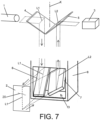
- the emitter 1 is configured for emitting the line of light L1 on the first upper plane mirror 4 in a horizontal manner, such that the line of light L1 reflected by the first lower plane mirror 6 is projected onto the inner surface 2 in a vertical manner.
- the emitter 1 emits a horizontal line of light L1, said horizontal line is emitted perpendicular to the axial axis X of the tube 8 and is projected in the first upper plane mirror 4 in a horizontal manner.
- the horizontal line of light L1 travels parallel to the axial axis X of the tube 8 between the first upper plane mirror 4 and the first lower plane mirror 6.
- the horizontal line of light L1 is projected in the first lower plane mirror 6 as an inclined vertical line, and said inclined vertical line is reflected in a manner perpendicular to the axial axis X of the tube 8 and is projected onto the inner surface 2 of the hollow body in a substantially vertical manner.
- Projecting the line of light L1 in a vertical manner improves the detection of circumferential defects in the inner surface 2 of the hollow body.
- the hollow body is a hole machined by means of a rotary cutting tool generating helices on the inner surface 2
- the projection of the line of light in a vertical manner allows defects 20 to be detected in a direction perpendicular to the axial axis of the machined hole.
- the tube 8 is a hollow rectangular body with four side faces 14, 15, 16, and 17.
- the first side face 14 has the first upper opening 11
- the second side face 15 has the lower opening 13
- the third side face 16 has the second upper opening 12, the second side face 15 being placed between the first side face 14 and the third side face 16.
- the mirrors 4, 5, 6, and 7 have a square or rectangular plane shape.
- the mirrors have a front face with a reflective surface, a rear face, and four minor faces joining the front face with the rear face.
- the mirrors are "first surface” mirrors. That is, the mirrors have their reflective surface facing the line of light.
- the reflective surface can be a reflective layer arranged on the front face, such as a metallic layer for example.
- the mirror can be made of a reflective material.
- the first upper plane mirror 4 is attached to the second and fourth side faces 15 and 17 of the tube 8
- the second upper plane mirror 5 is also attached to the second and fourth side faces 15 and 17 of the tube 8.
- the mirrors 4 and 5 can be adhered to the side faces 15 and 17 of the tube 8 by two of their opposing minor faces.
- the upper plane mirrors 4 and 5 are arranged at the upper end 9 of the tube 8 forming a V-shaped arrangement. This arrangement of the mirrors 4 and 5 makes it easier to assembly the mirrors at the upper end 9 of the tube 8 and allows there to be a more rigid assembly, such that the risk of the mirrors becoming misaligned in the event of impacts on the tube 8 is minimized.
- the first upper plane mirror 4 is inclined 45° with respect to the first side face 14
- the second upper plane mirror 5 is inclined 45° with respect to the third side face 16
- the first lower plane mirror 6 is inclined 45° with respect to the second side face 15
- the second lower plane mirror 7 is inclined 45° with respect to the second side face 15, and it is rotated a certain angle with respect to the first lower plane mirror 6.
- the light is emitted from the emitter 1 in a manner perpendicular to the axial axis X of the tube 8, travels parallel to the axial axis X of the tube 8, and is projected onto and reflected by the inner surface 2 in a manner substantially perpendicular to the axial axis X of the tube 8, travels again parallel to the axial axis X of the tube 8, and is reflected in a manner perpendicular to the axial axis X of the tube 8 towards the receiver 3 (see Figures 5 and 6 ).
- the light is thereby reflected at angles of 90°, the optical path of the light being reduced.
- the emitter 1 is attached to the first side face 14 of the tube 8 by means of a first L-shaped support 18, the emitter 1 being perpendicular to the axial axis X of the tube 8, and the receiver 3 is attached to the third side face 16 by means of a second L-shaped support 19, the receiver 3 being perpendicular to the axial axis X of the tube 8.
- the first support 18 has a vertical wing which is attached to the first side face 14 of the tube 8 and a horizontal wing which is attached to the emitter 1.
- the second support 19 has a vertical wing which is attached to the third side face 16 of the tube 8 and a horizontal wing which is attached to the receiver 3.
- the rigid attachment of the emitter 1 and the receiver 3 to the tube 8 ensures that the optical path of the light does not experience alterations, such that misalignments between the emitter 1, the receiver 3, and the mirrors 4, 5, 6, and 7 requiring recalibration of the device do not take place.
- the first and second lower plane mirrors 6 and 7 are preferably arranged in a removable support having means for being coupled to the inside of the lower end 10 of the tube 8. Different removable supports with mirrors 6 and 7 rotated at different angles based on the inner surface 2 to be inspected can thereby be used, without having to replace the tube 8. Tubes 8 of a different length are used depending on the depth of the hollow body to be inspected.
- the emitter 1 is a laser emitter, or an LED emitter with focusing lens.
- a laser emitter is preferably used because it makes it easier to focus the line of light, but when using coherent light resolution may be lost due to the Speckle noise effect.
- the LED emitter does not use coherent light and does not present this problem, but currently to create a line of light as narrow as a laser emitter does, LED technology requires using more power.
- the device additionally comprises translation means for generating a vertical translation T of the tube 8 with respect to the inner surface 2 of the hollow body and rotation means for generating a rotation R of the tube 8 with respect to the inner surface 2 of the hollow body.
- the translation and rotation means are an articulated robot having an arm with a free end where the upper end 9 of the tube 8 is coupleable.
- a six-axis articulated robot can be used, such that the arm of the robot can move and rotate the tube 8 during the inspection of the inner surface 2.
- the relative translation T and rotation R between the tube 8 and the hollow body can be performed in different ways. For example, if the hollow body is stationary, the translation and rotation means translate and rotate the tube 8 while the hollow body is stationary. If the tube 8 is stationary, the translation and rotation means translate and rotate the hollow body while the tube 8 is stationary. It is also possible to vertically translate the tube 8 and rotate the hollow body, or vertically translate the hollow body and rotate the tube 8.
- the method of inspection comprises emitting from the emitter 1 a line of light L1 onto the inner surface 2, generating a vertical translation T of the tube 8 with respect to the inner surface 2 of the hollow body, generating a rotation R of the tube 8 with respect to the inner surface 2 of the hollow body, capturing in the receiver 3 an image of the line of light L2 reflected by the inner surface 2, and processing the captured image to obtain the topography of the inner surface 2.
- the technique used for processing the captured image is laser triangulation.
- the vertical translation T is preferably parallel to the axial axis X of the tube 8 and the rotation R is performed on the axial axis X of the tube 8.
- the vertical translation T and the rotation R of the tube 8 with respect to the inner surface 2 are performed simultaneously, such that a helical light profile is projected onto the inner surface 2.
- the vertical translation T and the rotation R of the tube 8 with respect to the inner surface 2 are performed in an alternating manner, by means of vertical translational movements of the tube 8 with respect to the inner surface 2 alternating with rotational movements of the tube 8 with respect to the inner surface 2, such that annular light profiles are projected onto the inner surface 2.
Landscapes
- Physics & Mathematics (AREA)
- Health & Medical Sciences (AREA)
- Life Sciences & Earth Sciences (AREA)
- Chemical & Material Sciences (AREA)
- Analytical Chemistry (AREA)
- Biochemistry (AREA)
- General Health & Medical Sciences (AREA)
- General Physics & Mathematics (AREA)
- Immunology (AREA)
- Pathology (AREA)
- Engineering & Computer Science (AREA)
- Computer Vision & Pattern Recognition (AREA)
- Signal Processing (AREA)
- Investigating Materials By The Use Of Optical Means Adapted For Particular Applications (AREA)
- Length Measuring Devices By Optical Means (AREA)
- Instruments For Viewing The Inside Of Hollow Bodies (AREA)
Applications Claiming Priority (1)
| Application Number | Priority Date | Filing Date | Title |
|---|---|---|---|
| PCT/ES2020/070663 WO2022090585A1 (fr) | 2020-10-29 | 2020-10-29 | Dispositif et procédé d'inspection d'une surface intérieure d'un corps creux |
Publications (1)
| Publication Number | Publication Date |
|---|---|
| EP4239320A1 true EP4239320A1 (fr) | 2023-09-06 |
Family
ID=73598145
Family Applications (1)
| Application Number | Title | Priority Date | Filing Date |
|---|---|---|---|
| EP20812395.0A Pending EP4239320A1 (fr) | 2020-10-29 | 2020-10-29 | Dispositif et procédé d'inspection d'une surface intérieure d'un corps creux |
Country Status (6)
| Country | Link |
|---|---|
| US (1) | US20230273133A1 (fr) |
| EP (1) | EP4239320A1 (fr) |
| JP (1) | JP2023547139A (fr) |
| KR (1) | KR20230095955A (fr) |
| MX (1) | MX2023004609A (fr) |
| WO (1) | WO2022090585A1 (fr) |
Family Cites Families (5)
| Publication number | Priority date | Publication date | Assignee | Title |
|---|---|---|---|---|
| JPS61202109A (ja) * | 1985-03-05 | 1986-09-06 | Kawasaki Steel Corp | 管の内面検査装置 |
| GB8626812D0 (en) | 1986-11-10 | 1986-12-10 | Sira Ltd | Surface inspection |
| BE1005422A7 (fr) * | 1991-10-25 | 1993-07-20 | Challe Andre | Periscope optique pour l'examen interieur des tubes, ames de canons d'armes, ou autres utilisations dans lesquelles il n'est pas possible de demonter les elements a examiner. |
| JP5120625B2 (ja) * | 2008-03-07 | 2013-01-16 | アイシン精機株式会社 | 内面測定装置 |
| KR20200030650A (ko) * | 2018-09-12 | 2020-03-23 | 주식회사 씨메스 | 내경 검사 장치 |
-
2020
- 2020-10-29 EP EP20812395.0A patent/EP4239320A1/fr active Pending
- 2020-10-29 US US18/029,167 patent/US20230273133A1/en not_active Abandoned
- 2020-10-29 KR KR1020237013812A patent/KR20230095955A/ko not_active Withdrawn
- 2020-10-29 JP JP2023524648A patent/JP2023547139A/ja active Pending
- 2020-10-29 MX MX2023004609A patent/MX2023004609A/es unknown
- 2020-10-29 WO PCT/ES2020/070663 patent/WO2022090585A1/fr not_active Ceased
Also Published As
| Publication number | Publication date |
|---|---|
| WO2022090585A1 (fr) | 2022-05-05 |
| JP2023547139A (ja) | 2023-11-09 |
| KR20230095955A (ko) | 2023-06-29 |
| US20230273133A1 (en) | 2023-08-31 |
| MX2023004609A (es) | 2023-05-08 |
Similar Documents
| Publication | Publication Date | Title |
|---|---|---|
| EP3195989B1 (fr) | Appareil et procédé de localisation optique de pièce pour des opérations robotisées | |
| CN110045386B (zh) | 用于光检测与测距光学对准的方法与系统 | |
| US9146094B2 (en) | Automatic measurement of dimensional data with a laser tracker | |
| US7208749B2 (en) | System and method for locating and positioning an ultrasonic signal generator for testing purposes | |
| US20150253124A1 (en) | Automatic measurement of dimensional data within an acceptance region by a laser tracker | |
| US20150338210A1 (en) | Measuring device for acquiring surface data and/or interfaces of a workpiece to be processed by a laser processing device | |
| US10994372B2 (en) | Machine for laser working of tubes and profiled sections with a scanning system for scanning the tube or profiled section to be worked | |
| JP6817097B2 (ja) | 測量システム | |
| TWI642970B (zh) | 光學裝置、加工裝置及物品製造方法 | |
| US20040154402A1 (en) | Remote laser beam delivery system and method for use with a robotic positioning system for ultrasonic testing purposes | |
| EP3124163B1 (fr) | Système et procédé de traitement laser | |
| JP7414643B2 (ja) | 形状測定装置および形状測定方法 | |
| US9696143B2 (en) | Device for optical profilometry with conical light beams | |
| JP5242940B2 (ja) | 非接触形状測定装置 | |
| JP2001153632A (ja) | 医科的対象物、特に歯牙標本の模型を検出する方法と装置 | |
| US6836329B1 (en) | Real time IR optical sensor | |
| CN115574740A (zh) | 一种多功能光学自准直仪 | |
| EP4239320A1 (fr) | Dispositif et procédé d'inspection d'une surface intérieure d'un corps creux | |
| US20230142104A1 (en) | Method and device for generating a camera image of a welding seam for an image processing-supported laser transmission welding method | |
| JP7021569B2 (ja) | レーザレーダ装置 | |
| US11486972B2 (en) | Laser scanner | |
| JP2022013223A (ja) | レーザ加工装置の制御装置、レーザ加工装置、及びレーザ加工方法 | |
| JP7194296B2 (ja) | レーザスキャナ | |
| KR101953888B1 (ko) | 결함 분석을 위한 3차원 검사 장비 및 이의 위치 보정 방법 | |
| AU2007200013B2 (en) | System and method for locating and positioning an ultrasonic signal generator for testing purposes |
Legal Events
| Date | Code | Title | Description |
|---|---|---|---|
| STAA | Information on the status of an ep patent application or granted ep patent |
Free format text: STATUS: UNKNOWN |
|
| STAA | Information on the status of an ep patent application or granted ep patent |
Free format text: STATUS: THE INTERNATIONAL PUBLICATION HAS BEEN MADE |
|
| PUAI | Public reference made under article 153(3) epc to a published international application that has entered the european phase |
Free format text: ORIGINAL CODE: 0009012 |
|
| STAA | Information on the status of an ep patent application or granted ep patent |
Free format text: STATUS: REQUEST FOR EXAMINATION WAS MADE |
|
| 17P | Request for examination filed |
Effective date: 20230530 |
|
| AK | Designated contracting states |
Kind code of ref document: A1 Designated state(s): AL AT BE BG CH CY CZ DE DK EE ES FI FR GB GR HR HU IE IS IT LI LT LU LV MC MK MT NL NO PL PT RO RS SE SI SK SM TR |
|
| DAV | Request for validation of the european patent (deleted) | ||
| DAX | Request for extension of the european patent (deleted) | ||
| GRAP | Despatch of communication of intention to grant a patent |
Free format text: ORIGINAL CODE: EPIDOSNIGR1 |
|
| STAA | Information on the status of an ep patent application or granted ep patent |
Free format text: STATUS: GRANT OF PATENT IS INTENDED |
|
| INTG | Intention to grant announced |
Effective date: 20251007 |