EP4240583B1 - Ensemble vis et vis jumelle destiné à être utilisé dans des extrudeuses à mélange élastomère et procédé associé pour l'extrusion de mélanges élastomères - Google Patents
Ensemble vis et vis jumelle destiné à être utilisé dans des extrudeuses à mélange élastomère et procédé associé pour l'extrusion de mélanges élastomères Download PDFInfo
- Publication number
- EP4240583B1 EP4240583B1 EP21815266.8A EP21815266A EP4240583B1 EP 4240583 B1 EP4240583 B1 EP 4240583B1 EP 21815266 A EP21815266 A EP 21815266A EP 4240583 B1 EP4240583 B1 EP 4240583B1
- Authority
- EP
- European Patent Office
- Prior art keywords
- screw
- sector
- mixture
- intake
- twin
- Prior art date
- Legal status (The legal status is an assumption and is not a legal conclusion. Google has not performed a legal analysis and makes no representation as to the accuracy of the status listed.)
- Active
Links
Images


Classifications
-
- B—PERFORMING OPERATIONS; TRANSPORTING
- B30—PRESSES
- B30B—PRESSES IN GENERAL
- B30B11/00—Presses specially adapted for forming shaped articles from material in particulate or plastic state, e.g. briquetting presses, tabletting presses
- B30B11/22—Extrusion presses; Dies therefor
- B30B11/24—Extrusion presses; Dies therefor using screws or worms
- B30B11/246—Screw constructions
-
- B—PERFORMING OPERATIONS; TRANSPORTING
- B29—WORKING OF PLASTICS; WORKING OF SUBSTANCES IN A PLASTIC STATE IN GENERAL
- B29C—SHAPING OR JOINING OF PLASTICS; SHAPING OF MATERIAL IN A PLASTIC STATE, NOT OTHERWISE PROVIDED FOR; AFTER-TREATMENT OF THE SHAPED PRODUCTS, e.g. REPAIRING
- B29C48/00—Extrusion moulding, i.e. expressing the moulding material through a die or nozzle which imparts the desired form; Apparatus therefor
- B29C48/25—Component parts, details or accessories; Auxiliary operations
- B29C48/36—Means for plasticising or homogenising the moulding material or forcing it through the nozzle or die
- B29C48/395—Means for plasticising or homogenising the moulding material or forcing it through the nozzle or die using screws surrounded by a cooperating barrel, e.g. single screw extruders
- B29C48/40—Means for plasticising or homogenising the moulding material or forcing it through the nozzle or die using screws surrounded by a cooperating barrel, e.g. single screw extruders using two or more parallel screws or at least two parallel non-intermeshing screws, e.g. twin screw extruders
- B29C48/41—Intermeshing counter-rotating screws
-
- B—PERFORMING OPERATIONS; TRANSPORTING
- B29—WORKING OF PLASTICS; WORKING OF SUBSTANCES IN A PLASTIC STATE IN GENERAL
- B29C—SHAPING OR JOINING OF PLASTICS; SHAPING OF MATERIAL IN A PLASTIC STATE, NOT OTHERWISE PROVIDED FOR; AFTER-TREATMENT OF THE SHAPED PRODUCTS, e.g. REPAIRING
- B29C48/00—Extrusion moulding, i.e. expressing the moulding material through a die or nozzle which imparts the desired form; Apparatus therefor
- B29C48/25—Component parts, details or accessories; Auxiliary operations
- B29C48/36—Means for plasticising or homogenising the moulding material or forcing it through the nozzle or die
- B29C48/50—Details of extruders
- B29C48/505—Screws
- B29C48/59—Screws characterised by details of the thread, i.e. the shape of a single thread of the material-feeding screw
- B29C48/595—Screws characterised by details of the thread, i.e. the shape of a single thread of the material-feeding screw the thread having non-uniform width
-
- B—PERFORMING OPERATIONS; TRANSPORTING
- B29—WORKING OF PLASTICS; WORKING OF SUBSTANCES IN A PLASTIC STATE IN GENERAL
- B29C—SHAPING OR JOINING OF PLASTICS; SHAPING OF MATERIAL IN A PLASTIC STATE, NOT OTHERWISE PROVIDED FOR; AFTER-TREATMENT OF THE SHAPED PRODUCTS, e.g. REPAIRING
- B29C48/00—Extrusion moulding, i.e. expressing the moulding material through a die or nozzle which imparts the desired form; Apparatus therefor
- B29C48/25—Component parts, details or accessories; Auxiliary operations
- B29C48/36—Means for plasticising or homogenising the moulding material or forcing it through the nozzle or die
- B29C48/50—Details of extruders
- B29C48/69—Filters or screens for the moulding material
-
- B—PERFORMING OPERATIONS; TRANSPORTING
- B30—PRESSES
- B30B—PRESSES IN GENERAL
- B30B11/00—Presses specially adapted for forming shaped articles from material in particulate or plastic state, e.g. briquetting presses, tabletting presses
- B30B11/22—Extrusion presses; Dies therefor
- B30B11/24—Extrusion presses; Dies therefor using screws or worms
- B30B11/243—Extrusion presses; Dies therefor using screws or worms using two or more screws working in the same chamber
Definitions
- the present invention relates to a threaded screw for use in twin-screw extruders with intermeshing screws for extrusion and/or filtration of elastomer-based mixtures, a twin-screw extruder with intermeshing screws for elastomer mixtures and a method for extruding elastomer-based mixtures.
- elastomer materials such as elastomer-based mixtures or compounds, are amorphous materials which have a glass transition temperature which is lower than the ambient temperature.
- elastomer materials at temperatures higher than or the same as the ambient temperature are highly viscous (viscoelastic) fluids which are already “rubbery” and therefore do not need to be melted for further processing.
- These materials which are generally known as rubbers, include for example natural rubber, polybutadiene, polyisoprene, EPDM, NBR and SBR.
- this aperture has values ranging between 0.1 mm and 1 mm.
- the purpose of this operation is to retain in the filter, and therefore eliminate from the compound, any possible “bodies” (impurities, particles of unmixed materials, etc.). which have dimensions greater than the through-flow aperture of the filter meshes.
- a typical example is the compounds used to produce some visible profiles of cars such as, for example, window seals, for which the "perfect" surface appearance is an important feature that requires the elimination of any possible source of surface unevenness from the compounds used for this purpose.
- the compound In order for the compound to be filtered, it must be “pushed” or “forced” to flow through the filter, said operation being possible only if the compound is in a fluid state, namely has a "viscous” component which is predominant compared to the “elastic” component, this condition occurring when the compound is not crosslinked (not vulcanized) such that the polymer chains are not chemically bonded together.
- the elastomer compound In the non-crosslinked (so-called "raw") state, the elastomer compound may be regarded as being a "fluid” which is able to "flow” or "freely move".
- Filtration must therefore be performed in conditions where the compounds are not crosslinked and where the compounds are absolutely unable to crosslink during filtration; consequently, filtration is greatly conditioned by two main factors: temperature and pressure.
- the temperature must therefore be controlled by reducing the friction and/or by means of efficient dissipation of the heat generated.
- the value of the pressure, which is required in order to feed the compound during processing, is also dependent on the speed of the "fluid" which crosses the filter. All other conditions being equal, in order to obtain an increase in the productivity and therefore flowrate, it is required to increase precisely this speed, consequently increasing the pressure and therefore the temperature.
- the filtration process must be in general such as to ensure:
- CN102173004A provides a dual-rotor structure for continuous mastication of block rubber in order to output a continuous and high-quality rubber sheet, on which the preamble of Claim 1 is based.
- GB1,359,672 describes a single-screw or twin-screw extruder with non-intermeshing screws for the processing of plastic materials in the solid state such as PET, with heating means for melting the plastic material, wherein the volume comprised between adjacent crests of the thread of a screw is varied by means of "lands" projecting from the bottom of the threading.
- Such screws and extruder are not suitable for the extrusion and filtration of elastomer compounds since they have heating means (diathermic oil or electrical resistances) designed to heat the plastic material being processed to high temperatures necessary for melting (which would damage the elastomer material which on the contrary must not be melted) and non-intermeshing screws (resulting in play between the screws and therefore an excessive loss of flowrate such that sufficient pressure for extrusion/filtration of the elastomers cannot be reached). Moreover, the non-intermeshing screws operate along substantially separate and independent compound flow channels.
- the apparatus for filtering elastomer compounds include known intermeshing twin-screw/multiple-screw extruders which are generally counter-rotating and comprise screws configured to generate a high pressure of the compound at the filter.
- the greater the contact area with the compound the greater the probability that the properties of the compound being processed will change significantly, precisely because of the friction between compound and surface.
- the technical problem which is posed therefore is that of overcoming or at least reducing the drawbacks of the prior art, by providing in particular screws with an improved design suitable for application to a twin-screw extruder for elastomer mixtures, with axial discharging, in which they are arranged intermeshing, with parallel axis of rotation.
- a particular problem which is posed is that of creating a geometry of the screws such that air present in the elastomer mixture can be evacuated before filtration thereof and/or the increase in temperature and the variations in physical properties of the mixture being processed can be reduced.
- twin-screw assembly and/or extruder should be easy and inexpensive to produce and assemble, have small dimensions and be able to be easily installed also at any user location.
- the present invention relates furthermore to a method for extruding elastomer mixtures according to Claim 19.
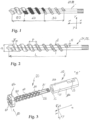
- a screw according to the present invention has a threaded part, the threading of which is of the single-start type, with the thread raised with respect to a core, and defines three different longitudinal sectors, i.e. 30, 40 and 50 respectively.
- the profile of the thread may have preferably a trapezoidal or flattened triangular form.
- a twin-screw assembly according to the invention comprises substantially:
- the cylinder has a suitable internal cavity with a form suitable for housing two screws, 21 and 22 respectively, arranged with their axes of rotation parallel and intermeshing and counter-rotating during use.
- the output zone 60 is arranged at the downstream end of the twin-screw assembly, said zone comprising a filtration zone 70 ( Fig. 5 ) into which the mixture is made to pass through the filter (not shown) in the feeding direction towards the discharge outlet.
- twin-screw assemblies in which the screws are in a mirror arrangement with respect to each other, although it is also possible to envisage different configurations of the two intermeshing and counter-rotating screws of the twin-screw assembly according to the invention.
- the cylinder and screw assembly defines three different sectors in the longitudinal direction ( Fig. 3 ) of the twin-screw assembly corresponding to the three longitudinal sectors of the threaded parts of the screws, i.e.:
- the three longitudinal sectors of the screws may be defined depending on the variation of the throughflow channel which is formed in the free volume inside the cylinder, with respect to the angle of rotation.
- the twin-screw assembly according to the present invention is characterized by a single throughflow channel which comprises from upstream to downstream at least three different sectors (20,30,40) of the screw along the longitudinal direction (X-X), which comprise:
- configurations of the geometry of the three longitudinal sectors of each screw have been developed so as to create laws of variation of the throughflow channel, and therefore of the C-chambers, which are such as to ensure an optimized configuration for the specific function for which each sector is intended.
- the geometries are such as to obtain at the same time a maximization of the intake performance at atmospheric pressure, corresponding to the intake sector for which C-chambers with a high volume, hence low crest width W, are required, with consequent maximization of the flowrate, and a maximization of the compression of the mixture in the high pressure sector 50 arranged immediately upstream of the filtration zone.
- the intake sector has the following parameters:
- the preferred geometric variables of the screws in the intake sector are such that, in a single-thread screw:
- the C-chambers in this zone have a constant volume less than in the other zones of the screw, so that the play is mechanically as small as possible.
- the high-pressure sector preferably has the following parameters:
- the screws of the twin-screw assembly according to the invention may advantageously be configured so as to obtain simultaneously: high pressures in the sector 50 close to the filter, where the play between screws and between screw and cylinder are relatively very small (in order to reduce the counter-flow opposing the main movement; and high capture and flowrate of the mixture in the intake zone, owing to the high free volumes, i.e. the space which can be potentially filled by the mixture.
- the transition sector between the intake sector, with low pressure and high volume of the C-chambers, and the high-pressure sector with low volume of the C-chambers upstream of the filtration zone is advantageously configured with a variable C-chamber volume, in particular so as to:
- the transition sector 40 has a decreasing volume of the C-chambers.
- the cross-section of the mixture throughflow channel preferably decreases in the direction of advancing movement of the mixture according to a law of variation which is substantially continuous, in particular at least partly approximately linear and/or quadratic and/or of an order greater than 2.
- the variation of the mixture throughflow channel in the transition sector is obtained with a geometry which varies the crest width W of the screw thread, while other parameters of the screw may reman constant in the transition sector.
- the transition sector has the following parameters:
- a gradual transition between the intake performance and the high-pressure performance is thus obtained.
- the variation of the throughflow channel may follow suitable laws, such as to optimize the required performance.
- the resultant effective flowrate Q is therefore obtained from the algebraic sum of the theoretical maximum flowrate ( Qth ) which is directly derived from the volume of the C-chambers) and the total flowrate loss ( QI ) which is due to the play between the screws and between screw and cylinder and the counter-flow due to the pressure:
- said assembly is configured so as to obtain a substantially constant effective flowrate Q along the longitudinal direction of advancing movement of the mixture from the input sector to the end of the high-pressure sector and, consequently, an efficiency calculated as the ratio Q/Q th which gradually increases towards the output zone.
- Figure 11 shows a schematic view of the cross-section S of the through-flow channel upon variation of the angle of rotation of the thread of a screw according to the present invention.
- the screw of Fig. 12a has a cross-section of the throughflow channel which is constant (and maximum) over three 360° rotations (3I) of the thread (three pitches) in the intake sector 30, decreases over three rotations of the thread in the transition zone and is constant (minimal) over two pitches (2P) in the high-pressure zone.
- the screw of Fig. 12b has a cross-section of the throughflow channel which is constant (and maximum) over four 360° rotations of the thread in the intake sector 30, decreases over one 360° rotation of the thread in the transition zone and is constant (minimal) over two pitches in the high-pressure zone.
- the C-chambers and the cross-section of the mixture throughflow channel for the twin-screw assembly according to Figs. 13b follow a similar law of variation, as illustrated in Fig.14b .
- the screw of Fig. 12c has a cross-section of the throughflow channel which is constant (and maximum) over four 360° rotations of the thread in the intake sector 30, decreases over two pitches (2L) of the thread in the transition zone and is constant (minimal) over two pitches in the high-pressure zone.
- the C-chambers and the cross-section of the mixture throughflow channel for the twin-screw assembly according to Figs. 13c follow a similar law of variation, as illustrated in Fig.14c .
- the screw and the twin-screw assembly in Figs. 12d , 13d , 14d are similar to those in Figs. 12c , 13c, 13d , but the variation of the cross-section in the transition sector 40 in this case has a decreasing quadratic progression (2L)
- the screw of Fig. 12e has a cross-section of the throughflow channel which is constant (and maximum) over four 360° rotations of the thread (three pitches) in the intake sector 30, decreases over three rotations of the thread in the transition zone and is constant (minimal) over a 360° rotation of the thread in the high-pressure zone 50.
- the extruded mixture filtration/output section 70 comprises a filter-holder plate 71 coupled to the connection flange 60 and closed by a shaped head 73.
- a "filter” (not shown here), generally consisting of a one or more metal meshes, is placed between the connection flange 61 and the filter-holder plate 71; the mixture is forced by the thrust produced by the rotation of the screws to flow across this filter which retains any impurities which are larger than the mesh aperture.
- one or more pressure and temperature sensors 61 are placed in the flange 60 and allow constant monitoring of the pressure and temperature of the mixture being processed, so as to obtain full control over the filtration step.
- Figs. 6,7 show cross-sections through the housing of the screws 21 and 22 inside the cylinder 10.
Landscapes
- Engineering & Computer Science (AREA)
- Mechanical Engineering (AREA)
- Extrusion Moulding Of Plastics Or The Like (AREA)
Claims (20)
- Vis (21; 22) adaptée pour être utilisée dans un ensemble double vis avec vis engrenées d'une extrudeuse de mélange d'élastomères, comprenant une partie filetée avec un filetage qui définit au moins trois secteurs différents (30, 40, 50) de vis selon une direction longitudinale (X-X) d'extension axiale de l'amont vers l'aval, dans laquelle les au moins trois secteurs comprennent :- un secteur d'admission (30), qui est adapté pour recevoir le mélange et le pousser vers l'aval selon la direction longitudinale (X-X) et qui présente une section transversale (S) du canal de passage comprise entre des flancs adjacents du filetage qui est constante sur au moins deux pas ou une rotation de 720 degrés du filetage ;- un secteur de transition (40), en aval du secteur d'admission, qui présente une section transversale (S) du canal de passage qui est variable et inférieure à la section transversale du canal de passage du secteur d'admission et qui est conçu pour provoquer une augmentation de la pression de poussée agissant sur le mélange en transit dans la direction longitudinale (X-X) ;- un secteur haute pression (50), en aval du secteur de transition, qui présente une section de canal de passage qui est minimale, constante sur au moins un pas et conçue pour provoquer la compression du mélange de manière à obtenir un pression maximale du mélange, caractérisée en ce que le filetage de ladite partie filetée est un filetage à un seul filet et en ce que la géométrie de la vis dans le secteur à haute pression (50) a une largeur de crête W = (0,3 - 0,4) D, constante sur un ou deux pas, dans laquelle D est le diamètre extérieur de la vis.
- Vis selon la revendication 1, caractérisée en ce que le secteur d'admission présente une section transversale de canal de passage et/ou une largeur (W) de la crête du filetage qui constante sur au moins deux pas, de préférence sur au moins trois pas, notamment sur deux, trois ou quatre pas.
- Vis selon la revendication 1 ou 2, caractérisée en ce que dans le secteur d'admission, la géométrie de la vis présente :• une Largeur de crête W = (0,025 - 0,20) D, de préférence (0,05 - 0,10) D, où D est le diamètre extérieur de la vis, qui est constante sur au moins deux, trois ou quatre pas ; et/ou• un Pas P du filetage qui est constant, de préférence égal au diamètre extérieur D ; et/ou• une Hauteur H du canal de passage H = (0,3 - 0,8) D, de préférence (0,54 - 0,6) D ; et/ou• une Longueur axiale de la zone d'admission Li = (3 - 4) P et/ou (3 - 4) D.
- Vis selon la revendication 1, 2 ou 3, caractérisée en ce que dans le secteur haute pression (50), la géométrie de la vis présente :- une Largeur de crête W = (0,3 - 0,4) D, de préférence (0,33 - 0,37) D, constante sur un ou deux pas ; et/ou- un Pas P constant, de préférence = D ; où D est le diamètre extérieur de la vis.
- Vis selon l'une des revendications précédentes, caractérisée en ce qu'elle présente un pas constant sur toute la partie filetée.
- Vis selon l'une des revendications précédentes, caractérisée en ce qu'elle présente une longueur de partie filetée inférieure ou égale à 10 D, où D est le diamètre extérieur de la vis, et/ou inférieure ou égale à 10 P, où P est le pas du filetage.
- Vis selon l'une des revendications précédentes, caractérisée en ce que dans le secteur de transition, la variation du canal de passage pour le passage du mélange est obtenue avec une géométrie qui fait varier la largeur de crête (W) du filetage de la vis.
- Vis selon la revendication précédente, dans laquelle dans le secteur de transition, la largeur de crête W est variable de manière continue entre une valeur minimale de W, correspondant à une largeur de crête du secteur d'admission, et une valeur maximale correspondant à une valeur de W du secteur haute pression; dans lequel la géométrie de la vis dans le secteur de transition présente de préférence :- un Pas P constant, de préférence égal au diamètre extérieur D ; et/ou- une Hauteur H du canal de passage de préférence constante et/ou comprise entre (0,3 - 0,12) D, de préférence (0,54 - 0,6) D ; et/ou- une longueur axiale du secteur de transition Lt = 1 - 3D ; où D est le diamètre extérieur de la vis.
- Ensemble à double vis (10, 20) pour extrudeuses de mélanges d'élastomères, comprenant deux vis (21, 22) avec une partie filetée ayant un filetage à un seul filet, qui sont disposées en prise et contrarotatives avec des axes de rotation longitudinaux parallèles (X-X) à l'intérieur d'un cylindre (10), de manière à former un canal d'écoulement pour le passage du flux de mélange constitué de l'union d'une pluralité de chambres en C (Cx), chacune définie par le volume libre à l'intérieur du cylindre (10) et comprenant en une seule rotation du filetage pour une seule vis, l'ensemble à double vis étant pourvu d'une ouverture amont (13) pour l'admission du mélange dans le canal de passage, dans lequel le canal de passage pour le passage du flux comprend, d'amont en aval dans la direction longitudinale (X-X) d'extension axiale des vis et d'avancement du mélange, au moins trois secteurs différents (30,40,50), qui inclut:- un secteur d'admission (30), qui est adapté pour recevoir le mélange introduit de l'extérieur et le pousser vers l'aval le long de la direction longitudinale (X-X) et qui présente un volume de chambres en C formant le canal d'écoulement pour le passage du flux qui est constant sur au moins deux pas du filetage de chaque vis ;- un secteur de transition (40), en aval du secteur d'admission, qui présente un volume des chambres en C formant le canal d'écoulement qui est variable, qui diminue et qui est plus petit que le volume des chambres en C du secteur d'admission ;- un secteur haute pression (50), en aval du secteur de transition, qui présente un volume des chambres en C formant le canal d'écoulement qui est constant sur au moins un pas et inférieur au volume des chambres en C des secteurs d'admission et de transition, et qui est adapté pour provoquer une compression du mélange de manière à obtenir une pression maximale du mélange;et dans lequel l'une et/ou l'autre des deux vis est/sont configurée(s) selon l'une des revendications 1 à 8.
- Ensemble à double vis selon la revendication précédente, caractérisé en ce que les vis sont disposées en image miroir.
- Ensemble à double vis selon l'une des revendications 9 et 10, dans lequel le secteur haute pression a un volume de chambres en C qui est constant sur au moins deux pas de chaque vis.
- Ensemble à double vis selon l'une des revendications 9 à 11, dans lequel le secteur d'admission a un volume de chambres en C qui est constant sur au moins trois, de préférence au moins quatre pas de chaque vis.
- Ensemble à double vis selon l'une des revendications 9 à 12, dans lequel le secteur de transition présente un volume de chambre en C diminuant dans le sens du mouvement d'avancement du mélange, et/ou une section transversale du canal d'écoulement pour le passage du flux de mélange, décroissant dans le sens du mouvement d'avancement du mélange, selon une loi de variation sensiblement continue, notamment au moins en partie approximativement linéaire et/ou quadratique et/ou d'ordre supérieur à 2.
- Ensemble à double vis selon l'une des revendications 9 à 13, dans lequel les vis et le cylindre sont disposés et configurés de manière à obtenir un débit effectif (Q) à travers le canal d'écoulement du mélange qui est constant le long de la direction longitudinale d'avancement du mélange depuis le secteur d'admission jusqu'à l'extrémité du secteur haute pression.
- Ensemble à double vis selon l'une des revendications 9 à 14, dans lequel :- dans le secteur d'admission :• O' = (0,0025 - 0,030) D, de préférence (0,005 - 0,015) D• δ = (0,0025 - 0,030) D, de préférence (0,005 - 0,015) D ; et/ou- dans le secteur haute pression :• O' = (0,0025 - 0,020) D, de préférence (0,005 - 0,015) D• δ = (0,0025 - 0,030) D, de préférence (0,005 - 0,015) D; et/ou- dans le secteur de la transition;où O' est une distance entre la crête d'une vis et le noyau de l'autre vis et δ est une distance entre la crête d'une vis et la surface interne de la cavité de chambre du cylindre contenant.• O' = (0,0025 - 0,030) D, de préférence (0,005 - 0,015) D;• δ = (0,025 - 0,030) D, de préférence (0,005 - 0,015) D;
- Ensemble à double vis selon l'une des revendications 9 à 15, dans lequel l'ouverture en amont est configurée pour alimenter le mélange vers le canal d'écoulement dans une direction (Z-Z) sensiblement orthogonale à la direction longitudinale (X-X).
- Extrudeuse de mélange d'élastomères, caractérisée en ce qu'elle comprend un ensemble à double vis s'étendant dans une direction longitudinale (X-X), selon l'une des revendications 9 à 16, et une tête d'extrusion aval (70).
- Extrudeuse selon la revendication précédente, caractérisée en ce qu'elle comprend une zone de filtration (70) munie d'un filtre à mailles, en aval de la zone haute pression (50), à travers laquelle on fait passer le mélange.
- Procédé d'extrusion de mélanges d'élastomères comprenant les étapes suivantes :- alimenter un mélange d'élastomères vers un ensemble à double vis selon l'une des revendications 9 à 15;
le mélange d'élastomères étant introduit à l'intérieur du canal d'écoulement pour le passage du flux de mélange de l'ensemble à double vis à travers une ouverture d'admission de mélange (13);- recevoir le mélange d'élastomères et le pousser vers l'aval à travers le canal d'écoulement pour l'écoulement du mélange, dans un secteur d'admission (30) de l'ensemble à double vis, qui présente un volume des chambres en C formant le canal d'écoulement qui est constant sur au moins deux pas de filetage de chaque vis;- mouvoir le mélange d'élastomères à travers un secteur de transition (40) du canal de passage pour le passage du flux de mélange, le secteur de transition (40) étant disposé en aval du secteur d'admission dans la direction longitudinale (X-X) d'extension axiale des vis et un mouvement d'avancement du mélange et ayant un volume des chambres en C formant le canal d'écoulement qui est variable, diminue et est plus petit que le volume des chambres en C du secteur d'admission;- mouvoir et compression du mélange d'élastomères dans un secteur haute pression (50) qui est disposé en aval du secteur de transition et qui présente un volume des chambres en C formant le canal d'écoulement qui est constant sur au moins un pas et inférieur au volume des chambres en C des secteurs d'admission et de transition de manière à provoquer la compression du mélange et obtenir une pression maximale du mélange;- passage du mélange d'élastomères à pression maximale à travers une tête d'extrusion (60) disposée en aval du secteur haute pression (50). - Procédé selon la revendication précédente, comprenant une filtration (70) du mélange en cours de traitement que l'on fait passer à travers un filtre à mailles en aval de la zone haute pression (50).
Applications Claiming Priority (2)
| Application Number | Priority Date | Filing Date | Title |
|---|---|---|---|
| IT202000026669 | 2020-11-09 | ||
| PCT/IB2021/060253 WO2022097076A1 (fr) | 2020-11-09 | 2021-11-05 | Ensemble vis et vis jumelle destiné à être utilisé dans des extrudeuses à mélange élastomère et procédé associé pour l'extrusion de mélanges élastomères |
Publications (3)
| Publication Number | Publication Date |
|---|---|
| EP4240583A1 EP4240583A1 (fr) | 2023-09-13 |
| EP4240583B1 true EP4240583B1 (fr) | 2024-12-18 |
| EP4240583C0 EP4240583C0 (fr) | 2024-12-18 |
Family
ID=74347561
Family Applications (1)
| Application Number | Title | Priority Date | Filing Date |
|---|---|---|---|
| EP21815266.8A Active EP4240583B1 (fr) | 2020-11-09 | 2021-11-05 | Ensemble vis et vis jumelle destiné à être utilisé dans des extrudeuses à mélange élastomère et procédé associé pour l'extrusion de mélanges élastomères |
Country Status (5)
| Country | Link |
|---|---|
| US (1) | US20230405908A1 (fr) |
| EP (1) | EP4240583B1 (fr) |
| JP (1) | JP2023551115A (fr) |
| CN (1) | CN116635206A (fr) |
| WO (1) | WO2022097076A1 (fr) |
Family Cites Families (16)
| Publication number | Priority date | Publication date | Assignee | Title |
|---|---|---|---|---|
| NL52125C (fr) * | 1939-03-31 | 1942-03-16 | ||
| FR960503A (fr) * | 1947-06-25 | 1950-04-20 | ||
| FR2093483A5 (fr) * | 1970-05-08 | 1972-01-28 | Plast Elastverarbeitungsmasch | |
| DE2222430A1 (de) * | 1972-05-08 | 1973-11-22 | Bucher Guyer Ag Masch | Plastifizierschnecke fuer spritzgiessmaschinen und extruder |
| FR2288475A1 (fr) * | 1973-12-28 | 1976-05-21 | Creusot Loire | Procede de decristallisation de matieres sucrees |
| JPS59167682A (ja) * | 1983-03-12 | 1984-09-21 | 株式会社 久永機工 | 汚泥乾燥装置 |
| US4944906A (en) * | 1988-10-11 | 1990-07-31 | Spirex Corporation | Methods of injection molding and extruding wet hygroscopic ionomers |
| JP3434418B2 (ja) * | 1996-07-24 | 2003-08-11 | 東芝機械株式会社 | 同方向回転2軸押出機による高融点樹脂の脱水システム |
| DE19718292A1 (de) * | 1997-04-30 | 1998-11-05 | Krupp Werner & Pfleiderer Gmbh | Mehrwellen-Schneckenmaschine, insbesondere Zwei-Wellen-Extruder |
| JP2002018835A (ja) * | 2000-07-11 | 2002-01-22 | Suzuka Fuji Xerox Co Ltd | 導電性熱可塑性樹脂の製造方法 |
| DE10122462C1 (de) * | 2001-05-09 | 2002-10-10 | 3 & Extruder Gmbh | Vorrichtung mit Schnecken zum Homogenisieren und/oder Dispergieren eines viskosen Stoffes und eines Feststoffes und/oder eines anderen Stoffes unterschiedlicher Viskosität |
| JP2003236831A (ja) * | 2002-02-18 | 2003-08-26 | Japan Steel Works Ltd:The | 二軸混練押出機 |
| CN102173004B (zh) * | 2011-01-25 | 2013-02-20 | 青岛科技大学 | 块状橡胶连续塑炼的双转子结构及采用该转子的塑炼设备 |
| JP6404035B2 (ja) * | 2014-08-25 | 2018-10-10 | 東洋機械金属株式会社 | 射出成形機のスクリュ |
| US10434483B2 (en) * | 2017-02-15 | 2019-10-08 | Wenger Manufacturing Inc. | High thermal transfer hollow core extrusion screw assembly |
| AU2018275182A1 (en) * | 2017-06-01 | 2019-07-25 | Wenger Manufacturing Inc. | High specific mechanical energy extrusion screw assembly |
-
2021
- 2021-11-05 WO PCT/IB2021/060253 patent/WO2022097076A1/fr not_active Ceased
- 2021-11-05 US US18/035,568 patent/US20230405908A1/en active Pending
- 2021-11-05 EP EP21815266.8A patent/EP4240583B1/fr active Active
- 2021-11-05 CN CN202180075516.0A patent/CN116635206A/zh active Pending
- 2021-11-05 JP JP2023527442A patent/JP2023551115A/ja active Pending
Also Published As
| Publication number | Publication date |
|---|---|
| JP2023551115A (ja) | 2023-12-07 |
| US20230405908A1 (en) | 2023-12-21 |
| CN116635206A (zh) | 2023-08-22 |
| EP4240583A1 (fr) | 2023-09-13 |
| EP4240583C0 (fr) | 2024-12-18 |
| WO2022097076A1 (fr) | 2022-05-12 |
Similar Documents
| Publication | Publication Date | Title |
|---|---|---|
| EP0764074B1 (fr) | Machine d'extrusion-compoundage multivis a elements de melange modulaires | |
| US5393213A (en) | Serial two-stage extruder | |
| EP2093037B1 (fr) | Segment de disque de malaxage et extrudeuse à vis jumelle | |
| CN104736317A (zh) | 用于加工易粘接的塑料的挤压机 | |
| WO2009153002A1 (fr) | Éléments de vis sans fin pour l'extrusion de matières plastiques, utilisation des éléments de vis sans fin et procédé d'extrusion | |
| US5215374A (en) | Plasticizing sections of cold feed rubber extruders | |
| US4863363A (en) | Throttling device for a twin-shaft srew-type extruder | |
| US7270471B2 (en) | Extruder | |
| DE1502335B2 (de) | Schneckenstrangprese fuer die verarbeitung von kunststoff | |
| EP2864104B1 (fr) | Procédé pour la fabrication d'un granulat de matière plastique, de profilés filés à la presse ou de pièces moulées | |
| CA1055217A (fr) | Extrudeuses a vis sans fin multiples et methode amelioree d'accroissement de la pression | |
| EP2889118A1 (fr) | Pompe de masse fondue pour faire passer une matière plastique en fusion par un outil | |
| US4356140A (en) | Extrusion method with short cycle multichannel wave screw | |
| EP4240583B1 (fr) | Ensemble vis et vis jumelle destiné à être utilisé dans des extrudeuses à mélange élastomère et procédé associé pour l'extrusion de mélanges élastomères | |
| JP6754018B1 (ja) | スクリュー、押出機及び押出方法 | |
| EP1396331B1 (fr) | Joint étanche pour véhicule sous forme de bande, procédé et dispositif pour sa fabrication | |
| US20060222727A1 (en) | Screw extruder | |
| US4818206A (en) | Multi-screw extruder | |
| WO1994002303A1 (fr) | Extrudeuse inverse | |
| DE102004042746A1 (de) | Extruderschnecke | |
| DE102013010505B4 (de) | Schmelzepumpe und Vorrichtung zur Herstellung von Kunststoffgranulat, Strangpressprofilen oder Formteilen | |
| DE102011009629A1 (de) | Extrusionsverfahren und -vorrichtung zur Verarbeitung von Kautschukmischung mit hohem Plastifizierbedarf | |
| EP1159120A1 (fr) | Extrudeuses monorotor | |
| KR102261450B1 (ko) | 스크루식 압출기 | |
| CN211868572U (zh) | 一种节能双螺杆挤出机 |
Legal Events
| Date | Code | Title | Description |
|---|---|---|---|
| STAA | Information on the status of an ep patent application or granted ep patent |
Free format text: STATUS: UNKNOWN |
|
| STAA | Information on the status of an ep patent application or granted ep patent |
Free format text: STATUS: THE INTERNATIONAL PUBLICATION HAS BEEN MADE |
|
| PUAI | Public reference made under article 153(3) epc to a published international application that has entered the european phase |
Free format text: ORIGINAL CODE: 0009012 |
|
| STAA | Information on the status of an ep patent application or granted ep patent |
Free format text: STATUS: REQUEST FOR EXAMINATION WAS MADE |
|
| 17P | Request for examination filed |
Effective date: 20230605 |
|
| AK | Designated contracting states |
Kind code of ref document: A1 Designated state(s): AL AT BE BG CH CY CZ DE DK EE ES FI FR GB GR HR HU IE IS IT LI LT LU LV MC MK MT NL NO PL PT RO RS SE SI SK SM TR |
|
| DAV | Request for validation of the european patent (deleted) | ||
| DAX | Request for extension of the european patent (deleted) | ||
| GRAP | Despatch of communication of intention to grant a patent |
Free format text: ORIGINAL CODE: EPIDOSNIGR1 |
|
| STAA | Information on the status of an ep patent application or granted ep patent |
Free format text: STATUS: GRANT OF PATENT IS INTENDED |
|
| RIC1 | Information provided on ipc code assigned before grant |
Ipc: B29C 48/595 20190101ALI20240527BHEP Ipc: B29C 48/41 20190101ALI20240527BHEP Ipc: B30B 11/24 20060101AFI20240527BHEP |
|
| INTG | Intention to grant announced |
Effective date: 20240617 |
|
| GRAS | Grant fee paid |
Free format text: ORIGINAL CODE: EPIDOSNIGR3 |
|
| GRAA | (expected) grant |
Free format text: ORIGINAL CODE: 0009210 |
|
| STAA | Information on the status of an ep patent application or granted ep patent |
Free format text: STATUS: THE PATENT HAS BEEN GRANTED |
|
| AK | Designated contracting states |
Kind code of ref document: B1 Designated state(s): AL AT BE BG CH CY CZ DE DK EE ES FI FR GB GR HR HU IE IS IT LI LT LU LV MC MK MT NL NO PL PT RO RS SE SI SK SM TR |
|
| REG | Reference to a national code |
Ref country code: CH Ref legal event code: EP |
|
| REG | Reference to a national code |
Ref country code: DE Ref legal event code: R096 Ref document number: 602021023669 Country of ref document: DE |
|
| REG | Reference to a national code |
Ref country code: IE Ref legal event code: FG4D |
|
| U01 | Request for unitary effect filed |
Effective date: 20250110 |
|
| U07 | Unitary effect registered |
Designated state(s): AT BE BG DE DK EE FI FR IT LT LU LV MT NL PT RO SE SI Effective date: 20250116 |
|
| PG25 | Lapsed in a contracting state [announced via postgrant information from national office to epo] |
Ref country code: HR Free format text: LAPSE BECAUSE OF FAILURE TO SUBMIT A TRANSLATION OF THE DESCRIPTION OR TO PAY THE FEE WITHIN THE PRESCRIBED TIME-LIMIT Effective date: 20241218 |
|
| PG25 | Lapsed in a contracting state [announced via postgrant information from national office to epo] |
Ref country code: NO Free format text: LAPSE BECAUSE OF FAILURE TO SUBMIT A TRANSLATION OF THE DESCRIPTION OR TO PAY THE FEE WITHIN THE PRESCRIBED TIME-LIMIT Effective date: 20250318 |
|
| PG25 | Lapsed in a contracting state [announced via postgrant information from national office to epo] |
Ref country code: GR Free format text: LAPSE BECAUSE OF FAILURE TO SUBMIT A TRANSLATION OF THE DESCRIPTION OR TO PAY THE FEE WITHIN THE PRESCRIBED TIME-LIMIT Effective date: 20250319 |
|
| PG25 | Lapsed in a contracting state [announced via postgrant information from national office to epo] |
Ref country code: RS Free format text: LAPSE BECAUSE OF FAILURE TO SUBMIT A TRANSLATION OF THE DESCRIPTION OR TO PAY THE FEE WITHIN THE PRESCRIBED TIME-LIMIT Effective date: 20250318 |
|
| PG25 | Lapsed in a contracting state [announced via postgrant information from national office to epo] |
Ref country code: SM Free format text: LAPSE BECAUSE OF FAILURE TO SUBMIT A TRANSLATION OF THE DESCRIPTION OR TO PAY THE FEE WITHIN THE PRESCRIBED TIME-LIMIT Effective date: 20241218 |
|
| PG25 | Lapsed in a contracting state [announced via postgrant information from national office to epo] |
Ref country code: PL Free format text: LAPSE BECAUSE OF FAILURE TO SUBMIT A TRANSLATION OF THE DESCRIPTION OR TO PAY THE FEE WITHIN THE PRESCRIBED TIME-LIMIT Effective date: 20241218 |
|
| PG25 | Lapsed in a contracting state [announced via postgrant information from national office to epo] |
Ref country code: ES Free format text: LAPSE BECAUSE OF FAILURE TO SUBMIT A TRANSLATION OF THE DESCRIPTION OR TO PAY THE FEE WITHIN THE PRESCRIBED TIME-LIMIT Effective date: 20241218 |
|
| PG25 | Lapsed in a contracting state [announced via postgrant information from national office to epo] |
Ref country code: IS Free format text: LAPSE BECAUSE OF FAILURE TO SUBMIT A TRANSLATION OF THE DESCRIPTION OR TO PAY THE FEE WITHIN THE PRESCRIBED TIME-LIMIT Effective date: 20250418 |
|
| PG25 | Lapsed in a contracting state [announced via postgrant information from national office to epo] |
Ref country code: SK Free format text: LAPSE BECAUSE OF FAILURE TO SUBMIT A TRANSLATION OF THE DESCRIPTION OR TO PAY THE FEE WITHIN THE PRESCRIBED TIME-LIMIT Effective date: 20241218 |
|
| PG25 | Lapsed in a contracting state [announced via postgrant information from national office to epo] |
Ref country code: CZ Free format text: LAPSE BECAUSE OF FAILURE TO SUBMIT A TRANSLATION OF THE DESCRIPTION OR TO PAY THE FEE WITHIN THE PRESCRIBED TIME-LIMIT Effective date: 20241218 |
|
| PLBE | No opposition filed within time limit |
Free format text: ORIGINAL CODE: 0009261 |
|
| STAA | Information on the status of an ep patent application or granted ep patent |
Free format text: STATUS: NO OPPOSITION FILED WITHIN TIME LIMIT |
|
| 26N | No opposition filed |
Effective date: 20250919 |
|
| U20 | Renewal fee for the european patent with unitary effect paid |
Year of fee payment: 5 Effective date: 20251121 |