EP4241995A1 - Tête d'impression à injection et son procédé de fabrication - Google Patents
Tête d'impression à injection et son procédé de fabrication Download PDFInfo
- Publication number
- EP4241995A1 EP4241995A1 EP23151377.1A EP23151377A EP4241995A1 EP 4241995 A1 EP4241995 A1 EP 4241995A1 EP 23151377 A EP23151377 A EP 23151377A EP 4241995 A1 EP4241995 A1 EP 4241995A1
- Authority
- EP
- European Patent Office
- Prior art keywords
- electrode
- voltage
- layer
- nozzle
- inkjet printhead
- Prior art date
- Legal status (The legal status is an assumption and is not a legal conclusion. Google has not performed a legal analysis and makes no representation as to the accuracy of the status listed.)
- Granted
Links
Images


Classifications
-
- B—PERFORMING OPERATIONS; TRANSPORTING
- B41—PRINTING; LINING MACHINES; TYPEWRITERS; STAMPS
- B41J—TYPEWRITERS; SELECTIVE PRINTING MECHANISMS, i.e. MECHANISMS PRINTING OTHERWISE THAN FROM A FORME; CORRECTION OF TYPOGRAPHICAL ERRORS
- B41J2/00—Typewriters or selective printing mechanisms characterised by the printing or marking process for which they are designed
- B41J2/005—Typewriters or selective printing mechanisms characterised by the printing or marking process for which they are designed characterised by bringing liquid or particles selectively into contact with a printing material
- B41J2/01—Ink jet
- B41J2/015—Ink jet characterised by the jet generation process
- B41J2/04—Ink jet characterised by the jet generation process generating single droplets or particles on demand
- B41J2/06—Ink jet characterised by the jet generation process generating single droplets or particles on demand by electric or magnetic field
-
- B—PERFORMING OPERATIONS; TRANSPORTING
- B41—PRINTING; LINING MACHINES; TYPEWRITERS; STAMPS
- B41J—TYPEWRITERS; SELECTIVE PRINTING MECHANISMS, i.e. MECHANISMS PRINTING OTHERWISE THAN FROM A FORME; CORRECTION OF TYPOGRAPHICAL ERRORS
- B41J2/00—Typewriters or selective printing mechanisms characterised by the printing or marking process for which they are designed
- B41J2/005—Typewriters or selective printing mechanisms characterised by the printing or marking process for which they are designed characterised by bringing liquid or particles selectively into contact with a printing material
- B41J2/01—Ink jet
- B41J2/135—Nozzles
- B41J2/14—Structure thereof only for on-demand ink jet heads
- B41J2/14201—Structure of print heads with piezoelectric elements
- B41J2/14233—Structure of print heads with piezoelectric elements of film type, deformed by bending and disposed on a diaphragm
Definitions
- the disclosure relates to an inkjet printhead and a method of manufacturing the same, and more particularly to an inkjet printhead and a method of manufacturing the same, in which a multi-nozzle is used to discharge ink in a hybrid way based on combination of a piezoelectric method and an induced electrohydrodynamic method that discharges a charged solution by electrostatic force induced on a liquid surface at the end of the nozzle.
- an inkjet printhead refers to a device that prints an image with predetermined colors on a surface of a printing medium by discharging fine droplets of ink to a desired position on the printing medium.
- the applications of the inkjet printhead have recently expanded to various fields such as a liquid crystal display (LCD), an organic light emitting device (OLED) and the like flat panel display fields; electronic (E)-paper and the like flexible display fields; metal wiring and the like printed electronics field; bio fields; and so on.
- Drop-on-demand (DOD) inkjet printhead is classified according to discharging methods into a piezoelectric inkjet printhead that discharges ink by pressure waves based on transformation of a piezoelectric body, and an electrohydrodynamic inkjet printhead that discharges ink by electrostatic force.
- a piezoelectric body vibrates a membrane to apply pressure to a chamber containing ink, thereby discharging the ink.
- droplets are discharged when pressure high enough to overcome the surface tension and viscosity of the ink on the surface of a nozzle is applied, and pressure applied additionally is required to be high enough to accelerate the discharged droplets to a speed at which these droplets can be accurately settled on a printing medium.
- the piezoelectric inkjet printhead needs to reduce transformation energy in a pressure chamber.
- the piezoelectric inkjet printhead is advantageous in that it is easy to control a printing job, and there are no restrictions on the types of ink because the discharging energy is based on mechanical transformation.
- the piezoelectric inkjet printhead has difficulty in discharging ultrafine droplets of several picoliters or less, and has a limitation in that the discharge of only ink having a viscosity of about 10 cPs is possible but the discharge of ink having a high viscosity is not possible. Further, it is difficult to discharge big droplets of 80 picoliters or more due to the limitations on the discharging energy.
- the piezoelectric inkjet printhead has a limitation even though volume uniformity of discharged droplets between a plurality of nozzles is very important for applications to the processes of the printed electronics such as a display, etc. unlike the existing graphic printing.
- the electrohydrodynamic inkjet printhead provides the discharging energy by applying electrostatic force to a liquid surface of ink formed at the end of a nozzle, and is therefore advantageous in that the discharge of ultrafine droplets of not more than several picoliters or femtoliters is possible and the discharge of ink droplets having a high viscosity of about 1,000 cPs is possible. Besides, it is also possible to discharge big droplets of 80 picoliters or more.
- the electrohydrodynamic inkjet printhead is advantageous for precise printing because a driving method is simple and the directionality of discharged ink droplets is excellent due to control based on distribution of an electric field formed on the nozzle.
- the electrohydrodynamic inkjet printhead has difficulty in cleaning the nozzle, which needs to be performed during a process, because the nozzle has a protruding structure for the concentration of the electric field.
- An inkjet head generally secures the stability of droplet jetting by cleaning the nozzle, which is contaminated with the ink, through wiping or the like process.
- a voltage of several hundred V to several KV is applied.
- a voltage controller having a very high slew rate is required to discharge the droplets by a DOD method.
- the electrohydrodynamic inkjet method has the maximum jetting frequency of about 1 kHz. However, this jetting frequency is very low as compared to the high jetting frequency of 100 kHz the foregoing piezoelectric inkjet method has.
- an electrohydrodynamic high-voltage electrode is disposed inside a nozzle, an ink chamber or an ink inlet.
- contact between the ink and the electrode causes an electro-chemical reaction that generates heat, and therefore problems arise in that the ink is denaturalized, bubbles are generated, the nozzle is clogged, etc.
- there have been many technical difficulties such as difficulties in processing a membrane structure of the piezoelectric body, an electrode for electrohydrodynamic inkjet driving, etc.
- Patent document 1 Korean Patent No. 10-0917279
- an aspect of the disclosure is to provide an inkjet printhead and a method of manufacturing the same, in which, as an inkjet apparatus having a layered multi-nozzle, a pressure wave based on oscillation of a piezoelectric body controls a liquid surface at the end of the nozzle, and a droplet is discharged by applying electrostatic force based on an induced electric field to the liquid surface, thereby overcoming viscosity and surface tension to discharge ultrafine droplets or large droplets based on combination between mechanical driving force of the piezoelectric body and the electrostatic force, and improving size uniformity of droplets between the nozzles based control of the electrostatic force for each nozzle.
- an inkjet printhead including: a first layer including an inlet formed to penetrate a substrate and introduce ink therein, and a plurality of membranes; a second layer disposed beneath the first layer, and including a manifold formed to penetrate a substrate and communicate with the inlet or recessed on a top of the substrate, and a plurality of nozzle channels formed to penetrate the substrate below the membrane and allow the ink transferred from the manifold to flow therein; a third layer disposed beneath the second layer, and including a plurality of nozzles formed in a substrate and communicating the plurality of nozzle channels; a piezoelectric actuator formed on the first layer formed with the membrane, and including a lower first electrode, a piezoelectric body on the first electrode, and a second electrode on the piezoelectric body; a first voltage controller configured to oscillate the membrane by applying a pulse voltage to the first electrode and the second electrode; a third electrode disposed beneath the third layer, formed around each nozzle, and
- the first layer may include a plurality of chambers recessed inward from a bottom thereof to store the ink and formed with the membrane above a top thereof.
- the chamber may include a first side communicating with the manifold, and a second side communicating with the nozzle channel.
- the inkjet printhead may further include a hydrophobic coating layer disposed beneath an insulating layer formed the insulator and coated with a hydrophobic material.
- the hydrophobic coating layer may be coated from an end of the nozzle to an inside of the nozzle.
- voltage applied by the first voltage controller may be synchronized with voltage applied by the second voltage controller.
- the second voltage controller may apply voltage to the third electrode to discharge a droplet when a meniscus is formed at an end of the nozzle as the first voltage controller applies a pulse voltage between the first electrode and the second to make the piezoelectric actuator oscillate the membrane, and the second voltage controller may apply a voltage having an opposite polarity to a discharging voltage or applies a voltage of 0V after the discharged droplet passes the third electrode.
- the inkjet printhead may further include a fourth electrode disposed beneath the third electrode, surrounded with an insulating layer, and disposed encompassing an outlet having a larger diameter than an opening of the nozzle; and a third voltage controller configured to apply voltage to the fourth electrode.
- voltage applied by the second voltage controller may be synchronized with voltage applied by the third voltage controller.
- a horizontal distance between the fourth electrode and the nozzle may be longer than a horizontal distance between the third electrode and the nozzle.
- the plurality of nozzles may be arranged in a matrix, and the third electrodes arranged in one of a row direction and a column direction may be electrically connected to simultaneously receive voltage from the second voltage controller, and the fourth electrodes arranged in the other one of the row direction and the column direction may be electrically connected to simultaneously receive voltage from the third voltage controller.
- the inkjet printhead may further include a fifth electrode disposed between the first layer and the second layer and surrounded with an insulating layer; and a fourth voltage controller configured to apply voltage to the fifth electrode.
- the first voltage controller may apply the same pulse voltage to the piezoelectric actuators respectively corresponding to the membranes, and the second voltage controller may apply different voltages to the third electrodes according to the nozzles to make droplets discharged from the nozzles be uniform in size.
- the fourth voltage controller may apply voltage, which has an opposite polarity to the voltage of the second voltage controller, to the fifth electrode, or may serve as the ground.
- the pulse voltage applied by the first voltage controller may be synchronized with the pulse voltage applied by the fourth voltage controller, so that electrostatic force based on potential difference between the first electrode and the fifth electrode can reinforce the oscillation of the membrane.
- the third electrodes may be formed as a single body for a plurality of nozzles.
- a method of manufacturing an inkjet printhead including: manufacturing a first layer including an inlet formed to penetrate a substrate and introduce ink therein, and a plurality of membranes on which a first electrode of a piezoelectric actuator is formed, a second layer including a manifold formed to penetrate a substrate and communicate with the inlet or recessed on a top of the substrate, and a plurality of nozzle channels formed to penetrate the substrate below the membrane and allow the ink transferred from the manifold to flow therein, and a third layer including a plurality of nozzles formed in a substrate and communicating the plurality of nozzle channels, and a third electrode disposed beneath the third layer, formed around each nozzle, and surrounded with an insulator; joining the first layer, the second layer, and the third layer in sequence; and forming a piezoelectric body and a second electrode for a piezoelectric actuator on the first electrode.
- the first layer may include a plurality of chambers recessed inward from a bottom thereof to store the ink and formed with the membrane above a top thereof.
- the method may further include coating a hydrophobic material on a lower layer of the insulator when the third layer is manufactured.
- a hydrophobic coating layer coated with the hydrophobic material may be coated from an end of the nozzle to an inside of the nozzle.
- the method may further include forming a fourth electrode, disposed beneath the third electrode, surrounded with an insulator, and having a larger diameter than the third electrode when the third layer is manufactured.
- the method may further include forming a fifth electrode disposed on the second layer and surrounded with an insulator when the third layer is manufactured.
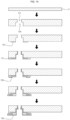
- FIG. 1 is a cross-sectional view of an inkjet printhead according to a first embodiment of the disclosure
- FIG. 2 is a view showing an operation of a membrane based on a piezoelectric body of FIG. 1 .
- An inkjet printhead may include a first layer 110, a second layer 120, a third layer 130, a piezoelectric actuator 140, a first voltage controller 145, an electrode (i.e., a third electrode 152) for electrohydrodynamic jetting, and a second voltage controller 155.
- the first layer (hereinafter, referred to as a chamber layer) 110 may be formed with an inlet 111 into which ink is introduced from the outside, and a plurality of membranes 115 which oscillates by the piezoelectric actuator 140.
- the inlet 111 is formed to vertically penetrate a substrate, which forming the chamber layer 110, at a predetermined position, and the substrate is formed with the thin membrane 115 having a predetermined thickness.
- the inlet 111 refers to an opening through which ink stored in an ink storage tank (not shown) flows into the inside of the printhead.
- a chamber 112 may be formed as recessed inward on the bottom of the substrate, and filled with the ink supplied through the inlet 111, and the membrane 115 may be formed above the chamber 112.
- a plurality of chambers 112 are spaced apart from each other in a direction perpendicular to FIG. 1 , and thus the chamber 112 and the membrane 115 are formed corresponding to each of a plurality of nozzles 131.
- a first electrode 141, a piezoelectric body 142 on the first electrode 141, and a second electrode 143 on the piezoelectric body 142, which form the piezoelectric actuator 140, may be stacked in sequence. Further, a pulse voltage may be applied between the first electrode 141 and the second electrode 143 through the first voltage controller 145.
- the first electrode 141 serves as a common electrode
- the second electrode 143 serves as a driving electrode for applying the pulse voltage to the piezoelectric body 142. Therefore, a plurality of second electrodes 143 may be individually disposed with regard to the plurality of nozzles 131.
- the piezoelectric body 142 may contain a predetermined piezoelectric material, for example, a piezoelectric transducer (PZT).
- the second electrode 143 on the piezoelectric body 142 is formed as the common electrode, and a plurality of first electrodes 141 beneath the piezoelectric body 142 are disposed corresponding to the plurality of nozzles 131, thereby applying the pulse voltage.
- the membrane 115 may be transformed up and down by the operation of the piezoelectric body 142.
- the membrane 115 serves as a vibrating plate that generates pressure waves in the chamber 112 based on the transformation of the membrane 115.
- the voltage applied by the first voltage controller 145 may be a pulse voltage in which a positive voltage or a negative voltage is periodically generated having a predetermined amplitude. Further, the voltage applied by the first voltage controller 145 may be a pulse voltage in which a positive voltage and a negative voltage are periodically generated having a predetermined amplitude. In addition, the voltage applied by the first voltage controller 145 may be an alternative current (AC) voltage having a predetermined waveform such as a sine wave, a triangular wave, and so on.
- AC alternative current
- the second layer (hereinafter, referred to as a channel layer) 120 is disposed beneath the chamber layer 110, and may include a manifold 121 formed penetrating a substrate having a predetermined thickness and communicating with the inlet 111, and a plurality of nozzle channels 122 formed penetrating the substrate and allowing the ink to flow from a first side of the manifold 121.
- a restrictor 113 is formed below a first side of the chamber 112 to communicate with the manifold 121 and communicates with the nozzle channel 122 below a second side of the chamber 112.
- the ink flowing from the outside into the chamber layer 110 through the inlet 111 is stored in the space of the manifold 121 formed together with the top of the nozzle layer 130, and the ink stored in the manifold 121 is transferred to each chamber 112 via the restrictor 113 and then transferred to the nozzle channel 122.
- the nozzle channel 122 is disposed between the chamber 112 of the chamber layer 110 and the nozzle 131 of the nozzle layer 130.
- the restrictor 113 serves to restrict the pressure waves traveling toward the nozzle and traveling toward the manifold 121 due to the transformation of the piezoelectric body 142.
- the cross-sectional area of the restrictor 113 may be equal to or smaller than the cross-sectional area of the nozzle channel 122.
- the manifold 121 penetrates the substrate and forms a space, in which the ink is stored, together with the top of the third layer 130.
- the manifold may be recessed on the top of the substrate at a predetermined depth without penetrating the substrate.
- the third layer (hereinafter, referred to as the nozzle layer 130) is disposed beneath the channel layer 120, and includes the plurality of nozzles 131 formed on a substrate having a predetermined thickness and communicating with the nozzle channel 122. Through the nozzle 131, the ink may be discharged forming a droplet toward a printing medium (not shown) put under the nozzle 131.
- the nozzle 131 is formed penetrating the nozzle layer 130.
- the nozzle 131 having a relatively small diameter may be formed in an upper portion, and an outlet 154 having a relatively large diameter may be formed in a lower portion. Therefore, openings are formed with stepped increase in diameter downward while penetrating the nozzle layer 130.
- a meniscus may be formed at not the end of the outlet 154 but the end of the nozzle 131 due to the operation of the piezoelectric actuator 140.
- a plurality of third electrodes 152 may be formed being surrounded with an insulating layer 151.
- the third electrode 152 may be formed in every nozzle 131.
- the third electrode 152 may have various shapes such as a circular shape, a horseshoe shape, a quadrangular shape, a diamond shape, etc.
- the third electrode 152 may be shaped to surround all or some of the nozzles 131.
- the third electrodes 152 formed in the nozzles 131 may be formed not separately but integrally.
- the third electrodes 152 are formed for the nozzles 131, and a connecting structure is formed for connection between adjacent third electrodes 152, thereby forming the third electrodes 152 as a single body.
- the third electrodes 152 may be individually formed being respectively separated from the nozzles 131.
- the third electrode 152 surrounded with the insulating layer 151 may be disposed beneath the bottom of the nozzle layer 130 in such a way that a first insulating layer is formed beneath the bottom of the nozzle layer 130, the third electrode 152 is formed beneath the first insulating layer, and a second insulating layer is formed beneath the third electrode 152.
- the third electrode 152 may be disposed directly under the nozzle layer 130 because the glass wafer is an insulating material, and the insulating layer 151 may be formed beneath the third electrode 152.
- the insulating layer may be formed not only beneath the bottom of the nozzle layer 130 but also on the inner surfaces of the outlet 154 and the nozzle 131.
- the third electrode 152 may be connected to the second voltage controller 155 and receive high voltage.
- a hydrophobic coating layer 160 coated with a hydrophobic material may be formed beneath the insulating layer 151.
- the hydrophobic coating layer 160 may prevent the bottom of the printhead, which is likely to come into contact with liquid, from contamination.
- the hydrophobic coating layer 160 may also be formed on the inner surface of the outlet 154.
- the hydrophobic coating layer 160 may be coated up to a predetermined depth of the nozzle 131 inward from the end.
- a droplet can be formed inside the nozzle 131, thereby increasing the printing stability and showing improvement in terms of maintenance.
- the chamber layer 110, the channel layer 120, and the nozzle layer 130 may be made of silicon wafers.
- the channel layer 120 and the nozzle layer 130 may also be made of glass wafers.
- the piezoelectric body 142 operates to oscillate the membrane 115 up and down.
- the oscillation of the membrane 115 transfers a pressure wave to the nozzle channel 122, so that a concave or convex meniscus can be formed at the end of the nozzle 131 by negative pressure or positive pressure of the pressure wave.
- the second voltage controller 155 applies high voltage to the third electrode 152 under the condition that the piezoelectric actuator 140 forms the convex meniscus at the end of the nozzle 131 with the positive pressure of the pressure wave, a droplet may be discharged from the meniscus by electrostatic force generated by induced charges.
- the membrane 115 is moved up by the piezoelectric actuator 140 and the chamber 112 is increased in volume, the change in pressure causes the ink stored in the manifold 121 to flow into the chamber 112 through the restrictor 113.
- Voltage applied to the third electrode 152 may be a positive or negative voltage having a predetermined amplitude.
- the voltage may be applied in the form of pulses, and thus synchronized with the pressure waves of the piezoelectric body 142.
- an AC voltage alternating between a positive voltage and a negative voltage may be applied, so that electric charges for discharging a droplet can be stabilized at the end of the nozzle 131.
- a constant bias voltage may be applied to the third electrode 152.
- an electrohydrodynamic inkjet apparatus that uses the electrostatic force to discharge a droplet, there is an on-set voltage with which the droplet starts being discharged with respect to the nozzle 131 having a specific size and the ink having a specific dielectric constant.
- the bias voltage may be equal to or lower than the on-set voltage.
- the second voltage controller 155 may apply high voltage to the third electrode 152 from time when the meniscus at the end of the nozzle 131 starts becoming convex by positive pressure as the first voltage controller 145 applies a voltage pulse for driving the piezoelectric body 142 and the pressure wave is transferred to the end of the nozzle 131.
- electrohydrodynamic discharge may actually start.
- the discharge in a given nozzle 131 may begin as an electric field is applied to a surrounding area of the nozzle 131 by the third electrode 152.
- the electric field is generated by difference in electric potential between the ink grounded or charged with specific polarity and the third electrode 152.
- the ink does not need to be grounded, but may be grounded to make the ink including charged particles or the like have uniform potential difference.
- the surface of the ink forming the convex meniscus may be charged.
- force is generated to change the shape of the meniscus.
- the electric field is strengthened to make the convex meniscus become more convex by increasing the potential difference between the third electrode 152 and the ink until stress electrically induced on the meniscus overcomes the surface tension of the ink, the discharge of the droplet may occur.
- a separate electrode for generating the electric field together with the third electrode 152 may be additionally provided under a printing medium.
- the voltage applied to the third electrode 152 may be controlled to fall to 0V after a droplet is detached from the meniscus formed at the end of the nozzle 131 by the voltage V applied to the third electrode 152 and passes the third electrode 152.
- the applied voltage may be controlled to have the opposite polarity (-V') after a droplet is detached from the meniscus formed at the end of the nozzle 131 by the voltage V applied to the third electrode 152 and passes the third electrode 152.
- the voltage applied to the third electrode 152 is controlled to fall to 0V or to have the opposite polarity after the droplet passes the third electrode 152, thereby solving the foregoing problems.
- force of repulsion may act on the droplet by the third electrode 152.
- the first voltage controller 145 and the second voltage controller 155 may apply synchronized voltages to the two electrodes 141 and 142 of the piezoelectric actuator 140 and the third electrode 152, respectively.
- the pulse time applied from the first voltage controller 145 is t1
- the waiting time until the next pulse voltage is applied is t6
- the time between when the pulse voltage is applied from the first voltage controller 145 and the voltage is applied from the second voltage controller 155 is t2
- the pulse time applied from the second voltage controller 155 is t3 ((a) of FIG. 3 )
- a pulse time of one polarity is t4
- a pulse time of the opposite polarity is t5
- the basic meniscus is formed by the voltage applied from the first voltage controller 145 and the droplet is jetted by the voltage applied from the second voltage controller 155, it must be synchronized with the following conditions.
- the third electrode 152 is formed below the nozzle 131 and separated from the nozzle 131 by the insulating layer 151. Therefore, the insulating layer 151, by which the third electrode 152 and the ink can be separated, prevents an oxidation-reduction reaction between the ink and the third electrode 152 when high voltage is applied to the third electrode 152, and solves problems such as heat generation, ink denaturalization, bubble generation, nozzle clogging, etc. due to the oxidation-reduction reaction.
- the third electrode 152 separated by the insulating layer 151 does not directly apply electric charges to a liquid surface of the nozzle 131, it is possible to concentrate induced charges on the liquid surface of the nozzle. Therefore, according to the disclosure, the droplets are discharged toward the printing medium by electrostatic force generated by induced charges when high voltage is applied to the third electrode 152.
- the nozzle 131 is provided as a multi-nozzle.
- the droplets discharged through the multi-nozzle may be different in size from each other.
- a conventional inkjet printhead using only the driving force of the piezoelectric body is capable of discharging droplets at an ultrahigh frequency of 100 kHz, but has a problem in that deviation in size between the droplets from the multi-nozzle is large.
- a drive per nozzle (DPN) inkjet printhead has been developed to individually control the piezoelectric body for each nozzle, but problems arise in that there is difficulty in the individual control, and it is difficult to optimize the shape of pulses for controlling the piezoelectric body for each nozzle.
- the first voltage controller 145 controls voltage to be equally applied to the piezoelectric actuators 140 respectively corresponding to the nozzles 131
- the second voltage controller 155 controls the voltage applied to the third electrode 152 to be different in level and frequency according to the nozzles 131, thereby controlling the droplets discharged from the multi-nozzle to be unform in size. It is much simpler to control the size of droplet based on the level of high voltage applied to the third electrode 152 than to control each pulse voltage for the piezoelectric actuator 140.
- the diameter of the droplet may be considerably smaller than the diameter of the nozzle 131 from which the droplet is discharged.
- the convex meniscus has a diameter given as the outer diameter of the entrance of the nozzle 131.
- the diameter of the droplet may be adjusted within a range from about 1/20 of the diameter of the nozzle 131 to the same diameter as the nozzle 131, by adjusting the voltage applied to the nozzle 131.
- a droplet smaller than 1/20 of the diameter of the nozzle 131 may also be producible.
- a droplet is varied in size. The droplet is increased in diameter as voltage increases between the minimum extraction voltage at which the applied voltage is needed for discharging the droplet and an extraction voltage approximately twice the minimum extraction voltage, and a diameter change rate of the droplet is decreased as the extraction voltage increases.
- the use of the nozzle 131 having a large diameter to produce much smaller droplets has various advantages. First, it is much easier to manufacture the nozzle 131 having a large diameter by the existing manufacturing method. Lowe resolution requirements may have a significant effect on costs and time required for manufacturing the printhead. Next, it is much faster to print a structure on a predetermined area of the substrate at a given resolution through the nozzle 131 having a large diameter. Further, when the discharged droplet has a diameter considerably smaller than the diameter of the nozzle 131, the discharging amount and the droplet size are much less affected by change in voltage.
- the droplets deposited by the nozzles 131 can have the same diameter and be discharged at the same frequency even though there is a slight difference in diameter between the manufactured nozzles 131.
- the nozzles are free from being clogged with contaminants or ink attached to and dried on the printhead. In addition, it is easier to clean the nozzle 131 having a larger diameter.
- the third electrode 152 may be formed encompassing the nozzle 131 below the end of the nozzle 131.
- FIG. 4 shows simulation results of effects on a liquid surface of a meniscus according to horizontal distances b between the third electrode 152 and the nozzle 131.
- the horizontal distance b between the third electrode 152 and the nozzle 131 gets shorter into 50 ⁇ m, 30 ⁇ m and 10 ⁇ m, wetting effects are increased as the third electrode 152 more attracts the edges of the meniscus. Therefore, the horizontal distance b between the third electrode 152 and the nozzle 131 needs to be designed to be greater than or equal to a predetermined minimum distance in order to prevent the wetting effects due to the force of attraction of the third electrode 152. In this case, the minimum distance may increase as the diameter of the nozzle 131 increases.
- FIG. 5 shows simulation results of effects on distribution of an electric field according to vertical distances a between the third electrode 152 and the end of the nozzle 131.
- the vertical distance a between the third electrode 152 and the nozzle 131 gets shorter, the droplet discharging energy increases due to the effects of the electric field but the concentration of the electric field decreases (see (a) in FIG. 5 ).
- the vertical distance a between the third electrode 152 and the nozzle 131 gets longer, the droplet discharging energy decreases but the concentration of the electric field increases (see (b) in FIG. 5 ).
- the concentration of the electric field decreases, the droplet may become unstable. Accordingly, the optimum vertical distance a between the third electrode 152 and the nozzle 131 is designed by taking the discharging energy of the droplet and the concentration of the electric field into account.
- the vertical distance a between the third electrode 152 and the nozzle 131 is much shorter than the distance between the printhead and the printing medium. Therefore, a strong electric field is locally formed around the nozzle 131 by not the distance between the printhead and the printing medium but the third electrode 152.
- FIG. 6 is a cross-sectional view of an inkjet printhead according to a second embodiment of the disclosure
- FIG. 7 illustrates a voltage applying structure of a third electrode and a fourth electrode
- FIG. 8 illustrates a voltage applying operation when ink is discharged from only some nozzles among the nozzles.
- the inkjet printhead has a three-layered structure of the chamber layer 110, the channel layer 120 and the nozzle layer 130.
- the third electrode 152 coated with the insulating layer 151 is disposed beneath the bottom of the nozzle layer 130.
- the third electrode 152 and a fourth electrode 153 are all disposed inside the insulating layer 151 beneath the nozzle layer 130, in which the fourth electrode 153 is disposed below and spaced apart from the third electrode 152, and the horizontal distance between the fourth electrode 153 and the nozzle 131 is designed to be longer than the horizontal distance between the third electrode 152 and the nozzle 131.
- the hydrophobic coating layer 160 coated with a hydrophobic material may be formed beneath the insulating layer 151 surrounding the third electrode 152 and the fourth electrode 153.
- a third voltage controller 157 applies voltage to the fourth electrode 153.
- the third voltage controller 157 applies voltage for forming the electrostatic force to the fourth electrode 153, thereby narrowing a discharging angle of droplets and reinforcing a discharging speed.
- the voltage applied to the fourth electrode 153 is synchronized to have the same phase as the voltage applied to the third electrode 152.
- the vertical distance between the third electrode 152 and the end of the nozzle 131 is much shorter than the distance between the printhead and the printing medium. Therefore, a strong electric field is locally formed around the nozzle 131 by not the distance between the printhead and the printing medium but the third electrode 152.
- the width of the third electrode 152 By limiting the width of the third electrode 152, it is possible to limit the area of the strong electric field to a place where the individual nozzles 131 is positioned, in a transverse direction, and narrow the distance between the nozzles 131. However, when the distance from the neighboring third electrodes 152 becomes closer, the electric field of the neighboring nozzle 131 may be affected. Thus, the fourth electrode 153 is useful for preventing the non-uniformity and transverse deflection of the electric field as affected by the electric field from the neighboring third electrode 152.
- the third electrode 152 needs to have the same polarity and a preferably higher amplitude as compared to extraction potential applied to liquid potential while the droplets are discharged, with regard to the droplets discharged as accelerated in an intended direction, i.e., a discharging direction.
- the accelerating electric field may be accurately orthogonal to the surface of the printing medium or the printhead, so that the droplet can be accelerated in a direction perpendicular to the surface of the printhead without being deflected in the transverse direction.
- Voltage applied to the fourth electrode 153 may be a direct current (DC) voltage, and may preferably be given in the form of a continuous signal having a constant or variable amplitude.
- the applied voltage may be an AC voltage, and may preferably be given in the form of a periodic function having a 20 Hz to 20 kHz.
- the inkjet printhead according to the disclosure may include the plurality of nozzles 131 arranged in a row direction and a column direction, forming a matrix.
- FIG. 7 shows an example that the nozzles 131 are arranged in a matrix having three rows and seven columns, but the arrangement of the nozzles 131 is not limited to this example.
- the third electrode 152 and the fourth electrode 153 surrounded with the insulating layer 151 may be arranged.
- the plurality of third electrodes 152 arranged in one of the row and column directions may be electrically connected in a straight line.
- FIG. 7 shows that seven third-electrodes 152 are electrically connected in the row direction, and thus three rows a, b and c of third electrodes 152 are connected to the second voltage controller 155.
- the fourth electrodes 153 arranged in one of the row and column directions may be electrically connected in a straight line.
- the third electrodes 152 and the fourth electrodes 153 are arranged being orthogonal to each other.
- the fourth electrode 153 may be electrically connected in the column direction.
- three fourth electrodes are electrically connected in the column direction, and thus seven columns 1, 2, 3, 4, 5, 6 and 7 of fourth electrodes 153 are connected to the third voltage controller 157.
- a voltage connection structure (circuit) may be complicated.
- the complicated voltage connection structure increases the distance between the nozzles 131, so that the plurality of nozzles 131 cannot be compactly arranged.
- the voltage controllers 155 and 157 may be burdened in terms of their capacities.
- the plurality of third electrodes 152 and the plurality of fourth electrodes 153 are electrically connected in the row direction or the column direction, thereby simplifying the voltage connection structure and lessening the burdens of the voltage controllers 155 and 157 in terms of capacity.
- voltage may be applied to lines connected to the electrodes 152 and 153 corresponding to these nozzles 131.
- the second voltage controller 155 and the third voltage controller 157 may apply voltage to the lines b, c, 1, 2 and 3 electrically connected to the third electrodes 152 and the fourth electrodes 153 corresponding to the marked nozzles 131.
- the lines b, c, 1, 2 and 3 may be on, but the lines a, 4, 5, 6 and 7 may be off.
- FIG. 9 is a cross-sectional view of the inkjet printhead according to the third embodiment of the disclosure
- FIG. 10 is a view showing an operation of a membrane based on a piezoelectric body and a fifth electrode of FIG. 9 .
- the inkjet printhead has a three-layered structure of the chamber layer 110, the channel layer 120 and the nozzle layer 130.
- this embodiment may additionally include a fifth electrode 171 surrounded with an insulating layer 170 and disposed on the channel layer 120. Therefore, the fifth electrode 171 surrounded with the insulating layer 170 may be disposed between the chamber layer 110 and the channel layer 120.
- a fourth voltage controller 175 applies voltage to the fifth electrode 171.
- the fifth electrode 171 in this embodiment may form a common electrode with regard to the plurality of nozzles 131.
- the fifth electrode 171 reinforces induced electric force by the third electrode 152, thereby assisting the ink in forming the meniscus. Actual triggering of droplet detachment may be caused by potential difference from the electrostatic force applied to the third electrode 152. With the fifth electrode 171, it is possible to decrease the minimum extraction voltage of the third electrode 152.
- the fifth electrode 171 may be used for generating potential difference from the electrostatic force of the third electrode 152.
- the fifth electrode 171 may receive voltage having the opposite polarity to that of the voltage applied to the third electrode 152, or may serve as the ground for the ink.
- the fifth electrode 171 together with the first electrode 141 of the piezoelectric actuator 140, generates the electrostatic force so that the membrane 115 can oscillate based on the electrostatic force.
- the electrostatic force between the first electrode 141 and the fifth electrode 171 may be added to the driving force of the piezoelectric body 142. Therefore, it is possible to reinforce the oscillation of the membrane 115 and precisely control the discharging force based on the oscillation of the membrane 115.
- FIG. 11 is a cross-sectional view of the inkjet printhead according to the fourth embodiment of the disclosure.
- the inkjet printhead has a three-layered structure of the chamber layer 110, the channel layer 120 and the nozzle layer 130.
- the fourth electrode 153 may be additionally provided.
- the third electrode 152 coated with the insulating layer 151 is disposed beneath the nozzle layer 130.
- the third electrode 152 and the fourth electrode 153 are all disposed inside the insulating layer 151 beneath the nozzle layer 130, in which the fourth electrode 153 is disposed below and spaced apart from the third electrode 152, and the horizontal distance between the fourth electrode 153 and the nozzle 131 is designed to be longer than the horizontal distance between the third electrode 152 and the nozzle 131.
- the hydrophobic coating layer 160 coated with a hydrophobic material may be formed beneath the insulating layer 151 surrounding the third electrode 152 and the fourth electrode 153.
- the third voltage controller 157 applies voltage to the fourth electrode 153.
- the third voltage controller 157 applies voltage for forming the electrostatic force to the fourth electrode 153, thereby narrowing a discharging angle of droplets and reinforcing a discharging speed.
- the voltage applied to the fourth electrode 153 is synchronized to have the same phase as the voltage applied to the third electrode 152.
- the vertical distance between the third electrode 152 and the end of the nozzle 131 is much shorter than the distance between the printhead and the printing medium. Therefore, a strong electric field is locally formed around the nozzle 131 by not the distance between the printhead and the printing medium but the third electrode 152.
- the fifth electrode 171 according to the third embodiment may be additionally provided.
- the fifth electrode 171 coated with the insulating layer 170 may be additionally disposed on the channel layer 120. Therefore, the insulating layer 170 may be disposed between the chamber layer 110 and the channel layer 120.
- the fourth voltage controller 175 applies voltage to the fifth electrode 171.
- the force of the pressure wave based on the oscillation of the piezoelectric body 142 by the first voltage controller 145 and the piezoelectric actuator 140, the force of induced electrostatic force by the second voltage controller 155 and the third electrode 152, the auxiliary force of the induced electrostatic force by the third voltage controller 157 and the fourth electrode 153, and the force of the pressure wave based on the induced electrostatic force or the electrostatic force by the fourth voltage controller 175 and the fifth electrode 171 are combined to produce the droplet at the end of the nozzle 131 and discharge the droplet while precisely controlling the discharging speed and direction of the droplet.
- FIG. 12 is a flowchart showing a method of manufacturing an inkjet printhead according to an embodiment of the disclosure
- FIG. 13 is a view showing a method of manufacturing a chamber layer
- FIG. 14 is a view showing a method of manufacturing a channel layer
- FIG. 15 is a view showing a method of manufacturing a nozzle layer.
- the method of manufacturing the inkjet printhead includes the steps of manufacturing the chamber layer 110 (or a first layer), the channel layer 120 (or a second layer), and the nozzle layer 130 (or a third layer) (S10); joining the chamber layer 110, the channel layer 120, and the nozzle layer 130 (S20); and forming the piezoelectric body 142 and the second electrode 143 of the piezoelectric actuator 140 on the chamber layer 110 (S30).
- the step of manufacturing the chamber layer 110 is illustrated in FIG. 13 .
- the chamber layer 110 may be manufactured with a silicon-on-insulator (SOI) wafer S.
- SOI wafer S The thickness of the SOI wafer S is adjusted to a designed value by a chemical mechanical planarization (CMP) process, and then Si is etched by a photo process and an etching process to process the plurality of chambers 112, thereby forming the membrane 115 on each chamber 112. Further, the inlet 111 is formed to penetrate the SOI wafer S.
- a lower electrode of the piezoelectric actuator 140 i.e., the first electrode 141 is formed on the chamber layer 110 by using a shadow mask and a sputter.
- the step of manufacturing the channel layer 120 is illustrated in FIG. 14 .
- the channel layer 120 may be manufactured with either an Si wafer S or a glass wafer S.
- the photo process and the etching process may be used like the method of manufacturing the chamber layer 110 when the manifold 121 and the plurality of nozzle channels 122 are formed.
- the channel layer 120 is manufactured to have a thickness of 400 ⁇ m to 500 ⁇ m.
- etching may be performed using a sand blast for chemical or physical etching.
- the induced electrostatic force may be reinforced by adding the fifth electrode 171 surrounded with the insulating layer 170 onto the channel layer 120, and the oscillation of the membrane 115 may be reinforced by the electrostatic force.
- the fifth electrode 171 may be insulated by a dielectric material.
- the shadow mask is aligned and the sputter is used to form a metal layer (i.e., the fifth electrode 171).
- the metal layer is protected with the insulating layer 170 of SiO 2 , so as not to be in direct contact with the ink.
- the shadow mask and the sputter are directly used to deposit the metal layer because the glass wafer S itself is an insulating material, and then the metal layer is protected by depositing the insulating layer 170 on the entire surface of the metal layer so as not to be in contact with ink.
- the insulating layer 170 and the fifth electrode 171 may be omitted.
- the step of manufacturing the nozzle layer 130 is illustrated in FIG. 15 .
- the method of manufacturing the nozzle layer 130 is similar to the method of manufacturing the chamber layer 110.
- the nozzle layer 130 may be manufactured with a Si wafer S. For more precis manufacturing, an SOI wafer S may be used. A glass wafer may also be used.
- the nozzle layer 130 may be manufactured to have a thickness of 200 ,um to 400 ,um.
- the photo process and the etching process are used to form a channel for the nozzle 131.
- the outlet 154 is formed by applying the photo process and the etching process to the bottom of the wafer S.
- the size of nozzle 131 may be varied depending on the size of droplets to be discharged. To discharge droplets of several picoliters or less, i.e., ultrafine droplets.
- the nozzle 131 may have a diameter of 10 ⁇ m or less. To discharge large droplets, the nozzle 131 may have a diameter of 50 ,um or more.
- the bottom of the nozzle layer 130 may be protected with the insulating layer 151. For example, SiOz may be deposited on the bottom of the nozzle layer 130. In this case, the insulating layer 151 may be formed encompassing the inside of the outlet 154 and the inside of the nozzle 131.
- the third electrode 152 for forming the induced electrostatic force may be formed beneath the nozzle layer 130.
- the third electrode 152 is surrounded with the insulating layer 151 so as not to be in contact with ink.
- the third electrodes 152 in this case may be integrally formed for the plurality of nozzles 131 or may be individually separated for the nozzles 131.
- the second voltage controller 155 applies voltage to the third electrode 152, charges are induced in the ink inside the nozzle 131 and thus droplets are discharged through the opening of the nozzle 131 by the electric field around the nozzle 131.
- DC voltage, DC pulse voltage, or AC voltage may be applied to the third electrode 152.
- the droplets may be discharged by a process that charges induced in the ink are continuously dissipated and induced again, and this process may be electrically construed as the flow of the induced current.
- the piezoelectric body 142 When the piezoelectric body 142 is operated by the continuous DC voltage and the pulse applied to the piezoelectric body 142 to discharge droplets, the droplets hit the printing medium while dissipating the induced charges, and it is therefore possible to discharge the droplets.
- the DC voltage may be lower than or equal to an onset voltage of when the droplet is discharged by only the electrostatic force.
- the most preferable voltage is the AC voltage.
- positive and negative charges are alternately generated, it is easier to continuously generate the induced charges.
- the DC voltage is applied, continuous ink operation is possible as described above without any problems because the induced charges are dissipated and new charges are induced in the ink as the droplets are discharged.
- the third electrode 152 is formed to surround the nozzle 131 by depositing the electrode layer on the insulating layer 151 formed beneath the nozzle layer 130, and then applying the photo process and the etching process to the deposited electrode layer.
- the third electrode 152 may have various shapes such as a circular shape, a horseshoe shape, a quadrangular shape, a diamond shape, etc. as long as it can surround all or some of the nozzles 131.
- the inner diameter of the third electrode 152 may be larger than or equal to the outer diameter of the nozzle 131.
- the third electrode 152 may be disposed to be surrounded with the insulating layer 151.
- SiO 2 , SiN x , etc. may be deposited as the insulating layer, and polyimide or the like polymer layer may be deposited.
- the third electrode 152 may be directly formed beneath the nozzle layer 130 without the insulating layer, and the insulating layer 151 may be formed beneath the third electrode 152, as shown in FIG. 15 .
- the insulating layer 151 may be formed even inside the outlet 154 and the nozzle 131.
- the fourth electrode 153 may be additionally formed below the third electrode 152 surrounded with the insulating layer 151, and the insulating layer 151 may be applied below the fourth electrode 153.
- the hydrophobic coating layer 160 made of hydrophobic material based on a fluoropolymer may be formed beneath the insulating layer 151.
- the water repellent layer may be formed by a spray coating method, an e-beam evaporator, a sputter or the like vacuum deposition.
- the hydrophobic coating layer 160 may be formed inward up to a predetermined depth from the end of the nozzle 131. When the hydrophobic coating layer 160 is formed, the hydrophobic coating layer 160 is coated while air is sprayed through the nozzle 131. In this case, the depth, up to which the hydrophobic coating layer 160 is coated on the inside of the nozzle 131, may be controlled according to the speeds of sprayed air.
- the chamber layer 110, the channel layer 120, the nozzle layer 130 are individually manufactured, and then the chamber layer 110, the channel layer 120, and the nozzle layer 130 are jointed together.
- the chamber layer 110 and the channel layer 120 are joined by anodic bonding, and then the nozzle layer 130 is joined beneath the channel layer 120 by anodic bonding.
- both the two layers to be joined are manufactured with the silicon wafer, they may be joined by direct bonding. Further, when the channel layer 120 is manufactured with the glass wafer, the anodic bonding may be used. When the channel layer 120 is manufactured with the Si wafer, Si direct bonding may be used.
- the lower electrode (i.e., the first electrode 141) of the piezoelectric actuator 140 is formed on the completed device.
- the piezoelectric body 142 is formed on the first electrode 141, and the second electrode 143 is deposited on the piezoelectric body 142, thereby completing the piezoelectric actuator 140.
- the piezoelectric body 142 may be fixed as a bulk piezoelectric body 142 onto the membrane 115 of the chamber layer 110 by bonding.
- the sputter may be used to deposit the piezoelectric body 142, and then the photo and etching processes may be performed.
- screen printing or the like printing method may be used to apply a material of the piezoelectric body 142, thereby forming the layer of the piezoelectric body 142.
- electrostatic force induced in a meniscus which is formed at the end of the nozzle by the pressure wave based on the operation of the piezoelectric body, is used to generate droplets, and it is thus possible to generate stronger discharging force than that of the inkjet printhead based on the operation of the piezoelectric body, thereby having advantages in that ink having a viscosity of 30 cP higher than 10 cP, which is the viscosity the ink dischargeable by the conventional inkjet printhead has, is dischargeable and even ink having a viscosity of 100 cP or higher is also dischargeable
- discharging power is so strong that droplets can be discharged even when the diameter of the nozzle is smaller than that of the conventional inkjet printhead, thereby having advantages in that ink droplets can be discharged at a femtoliter level (for reference, it is difficult for a conventional inkjet printhead to stably discharge droplets of not more than 1 picoliter (i.e., a diameter of 12.4 ⁇ m)).
- the nozzles of the multi-nozzle are controlled to be different in the level of the high voltage applied to the electrode for electrohydrodynamic jetting while an electric signal for driving the piezoelectric body is maintained constant, thereby having advantages in that the droplets discharged through the nozzles can be uniform in size.
- the fourth electrode is additionally disposed beneath the third electrode, thereby having advantageous in the discharging force and direction are more precisely controlled.
- the fifth electrode is additionally disposed between the channel layer and the chamber layer, thereby having advantageous in that the induced electrostatic force of the third electrode is reinforced or the oscillation of the membrane is strengthened by the electrostatic force acting between the first electrode and the fifth electrode.
Landscapes
- Particle Formation And Scattering Control In Inkjet Printers (AREA)
Applications Claiming Priority (3)
| Application Number | Priority Date | Filing Date | Title |
|---|---|---|---|
| KR20220029786 | 2022-03-10 | ||
| EP22164164 | 2022-03-24 | ||
| KR1020220169557A KR102826101B1 (ko) | 2022-03-10 | 2022-12-07 | 잉크젯 프린트헤드 및 상기 프린트헤드의 제작방법 |
Publications (3)
| Publication Number | Publication Date |
|---|---|
| EP4241995A1 true EP4241995A1 (fr) | 2023-09-13 |
| EP4241995B1 EP4241995B1 (fr) | 2025-07-23 |
| EP4241995C0 EP4241995C0 (fr) | 2025-07-23 |
Family
ID=84830030
Family Applications (1)
| Application Number | Title | Priority Date | Filing Date |
|---|---|---|---|
| EP23151377.1A Active EP4241995B1 (fr) | 2022-03-10 | 2023-01-12 | Tête d'impression à injection et son procédé de fabrication |
Country Status (1)
| Country | Link |
|---|---|
| EP (1) | EP4241995B1 (fr) |
Citations (4)
| Publication number | Priority date | Publication date | Assignee | Title |
|---|---|---|---|---|
| US20080074476A1 (en) * | 2006-09-27 | 2008-03-27 | Samsung Electro-Mechanics Co., Ltd. | Ink-jetting apparatus and ink-jetting method |
| KR100917279B1 (ko) | 2009-01-14 | 2009-09-16 | 건국대학교 산학협력단 | 액적분사장치 |
| US20110183478A1 (en) * | 2010-01-22 | 2011-07-28 | Samsung Electronics Co., Ltd. | Method of manufacturing TFT and array TFT |
| EP2567819A2 (fr) * | 2011-09-08 | 2013-03-13 | Samsung Electronics Co., Ltd. | Système d'impression, appareils d'impression et procédés de formation de buses d'injection des appareils d'impression |
-
2023
- 2023-01-12 EP EP23151377.1A patent/EP4241995B1/fr active Active
Patent Citations (4)
| Publication number | Priority date | Publication date | Assignee | Title |
|---|---|---|---|---|
| US20080074476A1 (en) * | 2006-09-27 | 2008-03-27 | Samsung Electro-Mechanics Co., Ltd. | Ink-jetting apparatus and ink-jetting method |
| KR100917279B1 (ko) | 2009-01-14 | 2009-09-16 | 건국대학교 산학협력단 | 액적분사장치 |
| US20110183478A1 (en) * | 2010-01-22 | 2011-07-28 | Samsung Electronics Co., Ltd. | Method of manufacturing TFT and array TFT |
| EP2567819A2 (fr) * | 2011-09-08 | 2013-03-13 | Samsung Electronics Co., Ltd. | Système d'impression, appareils d'impression et procédés de formation de buses d'injection des appareils d'impression |
Also Published As
| Publication number | Publication date |
|---|---|
| EP4241995B1 (fr) | 2025-07-23 |
| EP4241995C0 (fr) | 2025-07-23 |
Similar Documents
| Publication | Publication Date | Title |
|---|---|---|
| KR102504707B1 (ko) | 다노즐 프린트 헤드 | |
| US5828394A (en) | Fluid drop ejector and method | |
| KR100471793B1 (ko) | 잉크제트기록장치와그제조방법 | |
| US12403691B2 (en) | Inkjet printhead and method of manufacturing the same | |
| JP6327493B2 (ja) | プリンティング装置 | |
| KR101567506B1 (ko) | 잉크젯 프린팅 장치 및 그 구동 방법 | |
| US7571984B2 (en) | Drop discharge head and method of producing the same | |
| KR101968636B1 (ko) | 잉크젯 프린팅 장치 및 노즐 형성 방법 | |
| KR101941168B1 (ko) | 잉크젯 프린팅 장치 | |
| KR101615633B1 (ko) | 잉크젯 프린팅 장치의 구동 방법 | |
| KR101890755B1 (ko) | 잉크젯 프린팅 장치 및 노즐 형성 방법 | |
| KR100917279B1 (ko) | 액적분사장치 | |
| TWI910522B (zh) | 噴墨印刷頭 | |
| KR20130082316A (ko) | 하이브리드 잉크젯 프린팅 장치의 구동방법 | |
| KR101569837B1 (ko) | 잉크젯 프린팅 장치 및 그 구동 방법 | |
| KR102826101B1 (ko) | 잉크젯 프린트헤드 및 상기 프린트헤드의 제작방법 | |
| US20080036820A1 (en) | Apparatus and Method for Jetting Droplet Using Electrostatic Field | |
| EP4241995B1 (fr) | Tête d'impression à injection et son procédé de fabrication | |
| US7703870B2 (en) | Liquid ejection apparatus | |
| JP2011218715A (ja) | 液体吐出ヘッド | |
| JPH11300975A (ja) | 液体微粒子化装置 | |
| EP4733070A1 (fr) | Tête d'impression à jet d'encre | |
| TWI910988B (zh) | 噴墨印刷頭 | |
| US12528289B2 (en) | Liquid droplet discharging apparatus | |
| KR100243041B1 (ko) | 잉크분사장치 |
Legal Events
| Date | Code | Title | Description |
|---|---|---|---|
| PUAI | Public reference made under article 153(3) epc to a published international application that has entered the european phase |
Free format text: ORIGINAL CODE: 0009012 |
|
| STAA | Information on the status of an ep patent application or granted ep patent |
Free format text: STATUS: THE APPLICATION HAS BEEN PUBLISHED |
|
| AK | Designated contracting states |
Kind code of ref document: A1 Designated state(s): AL AT BE BG CH CY CZ DE DK EE ES FI FR GB GR HR HU IE IS IT LI LT LU LV MC ME MK MT NL NO PL PT RO RS SE SI SK SM TR |
|
| STAA | Information on the status of an ep patent application or granted ep patent |
Free format text: STATUS: REQUEST FOR EXAMINATION WAS MADE |
|
| 17P | Request for examination filed |
Effective date: 20240312 |
|
| RBV | Designated contracting states (corrected) |
Designated state(s): AL AT BE BG CH CY CZ DE DK EE ES FI FR GB GR HR HU IE IS IT LI LT LU LV MC ME MK MT NL NO PL PT RO RS SE SI SK SM TR |
|
| GRAP | Despatch of communication of intention to grant a patent |
Free format text: ORIGINAL CODE: EPIDOSNIGR1 |
|
| STAA | Information on the status of an ep patent application or granted ep patent |
Free format text: STATUS: GRANT OF PATENT IS INTENDED |
|
| INTG | Intention to grant announced |
Effective date: 20250220 |
|
| GRAS | Grant fee paid |
Free format text: ORIGINAL CODE: EPIDOSNIGR3 |
|
| GRAA | (expected) grant |
Free format text: ORIGINAL CODE: 0009210 |
|
| STAA | Information on the status of an ep patent application or granted ep patent |
Free format text: STATUS: THE PATENT HAS BEEN GRANTED |
|
| AK | Designated contracting states |
Kind code of ref document: B1 Designated state(s): AL AT BE BG CH CY CZ DE DK EE ES FI FR GB GR HR HU IE IS IT LI LT LU LV MC ME MK MT NL NO PL PT RO RS SE SI SK SM TR |
|
| REG | Reference to a national code |
Ref country code: GB Ref legal event code: FG4D |
|
| REG | Reference to a national code |
Ref country code: CH Ref legal event code: EP |
|
| REG | Reference to a national code |
Ref country code: IE Ref legal event code: FG4D |
|
| REG | Reference to a national code |
Ref country code: DE Ref legal event code: R096 Ref document number: 602023004910 Country of ref document: DE |
|
| U01 | Request for unitary effect filed |
Effective date: 20250821 |
|
| U07 | Unitary effect registered |
Designated state(s): AT BE BG DE DK EE FI FR IT LT LU LV MT NL PT RO SE SI Effective date: 20250827 |
|
| PG25 | Lapsed in a contracting state [announced via postgrant information from national office to epo] |
Ref country code: IS Free format text: LAPSE BECAUSE OF FAILURE TO SUBMIT A TRANSLATION OF THE DESCRIPTION OR TO PAY THE FEE WITHIN THE PRESCRIBED TIME-LIMIT Effective date: 20251123 |
|
| PG25 | Lapsed in a contracting state [announced via postgrant information from national office to epo] |
Ref country code: NO Free format text: LAPSE BECAUSE OF FAILURE TO SUBMIT A TRANSLATION OF THE DESCRIPTION OR TO PAY THE FEE WITHIN THE PRESCRIBED TIME-LIMIT Effective date: 20251023 |
|
| PG25 | Lapsed in a contracting state [announced via postgrant information from national office to epo] |
Ref country code: HR Free format text: LAPSE BECAUSE OF FAILURE TO SUBMIT A TRANSLATION OF THE DESCRIPTION OR TO PAY THE FEE WITHIN THE PRESCRIBED TIME-LIMIT Effective date: 20250723 |
|
| PG25 | Lapsed in a contracting state [announced via postgrant information from national office to epo] |
Ref country code: GR Free format text: LAPSE BECAUSE OF FAILURE TO SUBMIT A TRANSLATION OF THE DESCRIPTION OR TO PAY THE FEE WITHIN THE PRESCRIBED TIME-LIMIT Effective date: 20251024 |
|
| PG25 | Lapsed in a contracting state [announced via postgrant information from national office to epo] |
Ref country code: PL Free format text: LAPSE BECAUSE OF FAILURE TO SUBMIT A TRANSLATION OF THE DESCRIPTION OR TO PAY THE FEE WITHIN THE PRESCRIBED TIME-LIMIT Effective date: 20250723 |
|
| PG25 | Lapsed in a contracting state [announced via postgrant information from national office to epo] |
Ref country code: RS Free format text: LAPSE BECAUSE OF FAILURE TO SUBMIT A TRANSLATION OF THE DESCRIPTION OR TO PAY THE FEE WITHIN THE PRESCRIBED TIME-LIMIT Effective date: 20251023 |
|
| PG25 | Lapsed in a contracting state [announced via postgrant information from national office to epo] |
Ref country code: ES Free format text: LAPSE BECAUSE OF FAILURE TO SUBMIT A TRANSLATION OF THE DESCRIPTION OR TO PAY THE FEE WITHIN THE PRESCRIBED TIME-LIMIT Effective date: 20250723 |
|
| U20 | Renewal fee for the european patent with unitary effect paid |
Year of fee payment: 4 Effective date: 20260115 |
|
| PG25 | Lapsed in a contracting state [announced via postgrant information from national office to epo] |
Ref country code: SM Free format text: LAPSE BECAUSE OF FAILURE TO SUBMIT A TRANSLATION OF THE DESCRIPTION OR TO PAY THE FEE WITHIN THE PRESCRIBED TIME-LIMIT Effective date: 20250723 |
|
| PG25 | Lapsed in a contracting state [announced via postgrant information from national office to epo] |
Ref country code: CZ Free format text: LAPSE BECAUSE OF FAILURE TO SUBMIT A TRANSLATION OF THE DESCRIPTION OR TO PAY THE FEE WITHIN THE PRESCRIBED TIME-LIMIT Effective date: 20250723 |
|
| PG25 | Lapsed in a contracting state [announced via postgrant information from national office to epo] |
Ref country code: SK Free format text: LAPSE BECAUSE OF FAILURE TO SUBMIT A TRANSLATION OF THE DESCRIPTION OR TO PAY THE FEE WITHIN THE PRESCRIBED TIME-LIMIT Effective date: 20250723 |