EP4242094A2 - Tendeur de ligne de fond d'une structure flottante - Google Patents
Tendeur de ligne de fond d'une structure flottante Download PDFInfo
- Publication number
- EP4242094A2 EP4242094A2 EP23175475.5A EP23175475A EP4242094A2 EP 4242094 A2 EP4242094 A2 EP 4242094A2 EP 23175475 A EP23175475 A EP 23175475A EP 4242094 A2 EP4242094 A2 EP 4242094A2
- Authority
- EP
- European Patent Office
- Prior art keywords
- mooring line
- tensioner
- tensioner according
- stabilizing platform
- attached
- Prior art date
- Legal status (The legal status is an assumption and is not a legal conclusion. Google has not performed a legal analysis and makes no representation as to the accuracy of the status listed.)
- Withdrawn
Links
Images


Classifications
-
- B—PERFORMING OPERATIONS; TRANSPORTING
- B63—SHIPS OR OTHER WATERBORNE VESSELS; RELATED EQUIPMENT
- B63B—SHIPS OR OTHER WATERBORNE VESSELS; EQUIPMENT FOR SHIPPING
- B63B21/00—Tying-up; Shifting, towing, or pushing equipment; Anchoring
- B63B21/50—Anchoring arrangements or methods for special vessels, e.g. for floating drilling platforms or dredgers
-
- B—PERFORMING OPERATIONS; TRANSPORTING
- B63—SHIPS OR OTHER WATERBORNE VESSELS; RELATED EQUIPMENT
- B63B—SHIPS OR OTHER WATERBORNE VESSELS; EQUIPMENT FOR SHIPPING
- B63B21/00—Tying-up; Shifting, towing, or pushing equipment; Anchoring
- B63B21/04—Fastening or guiding equipment for chains, ropes, hawsers, or the like
-
- B—PERFORMING OPERATIONS; TRANSPORTING
- B63—SHIPS OR OTHER WATERBORNE VESSELS; RELATED EQUIPMENT
- B63B—SHIPS OR OTHER WATERBORNE VESSELS; EQUIPMENT FOR SHIPPING
- B63B21/00—Tying-up; Shifting, towing, or pushing equipment; Anchoring
- B63B21/50—Anchoring arrangements or methods for special vessels, e.g. for floating drilling platforms or dredgers
- B63B2021/505—Methods for installation or mooring of floating offshore platforms on site
Definitions
- the present invention relates to tensioners of mooring lines of floating structures.
- Floating structures such as drilling vessels or offshore platforms, have to be moored to the seabed in a given fixed area, so as to not be subjected to the displacements that may be caused by sea currents or atmospheric conditions.
- Anchoring devices of different types which are moored to mooring lines that are attached to said vessels or platforms are used. Initially, when floating structures are moored to the seabed the mooring lines must be tensioned in order to keep said floating structures in place. Over time, the mooring lines loosen and they must be tensioned again. The mooring lines are tensioned with tensioners.
- US20160185427A1 describes a tensioner of a mooring line of a floating structure, the mooring line comprising a first mooring line and a second mooring line, with said mooring lines being separate from one another, wherein one of said mooring lines comprises a first end attached to the floating structure, and the other mooring line comprises a first end attached to an anchoring device which is secured to the seabed, the tensioner comprising an elongated body with a base and a longitudinal housing configured for housing a chain segment of the first mooring line, a connection unit attached to the body at one of its ends comprising a connector member configured for attaching a second end of the second mooring line to the body, and an inlet unit attached to the body at the other end and configured for inserting a second end of the first mooring line into the housing of the body, the body comprising an opening in the upper part for the passage of the second end of the first mooring line from the inlet unit, through the housing, and along a
- the object of the invention is to provide a tensioner of a mooring line of a floating structure, as defined in the claims.
- the tensioner of the invention is a tensioner of a mooring line of a floating structure, wherein the mooring line comprises a first mooring line and a second mooring line, with said mooring lines being separate from one another, wherein one of said mooring lines comprises a first end attached to the floating structure, and the other mooring line comprises a first end attached to an anchoring device which is secured to the seabed,
- the tensioner comprising an elongated body with a base and a longitudinal housing configured for housing a chain segment of the first mooring line, a connection unit attached to the body at one of its ends comprising a connector member configured for attaching a second end of the second mooring line to the body, and an inlet unit attached to the body at the other end and configured for inserting a second end of the first mooring line into the housing of the body, the body comprising an opening in the upper part for the passage of the second end of the first mooring line from the inlet unit, through the housing, and along
- the tensioner comprises a stabilizing platform, with the body being fixed to the stabilizing platform and said stabilizing platform projecting laterally from said body.
- the tensioner may sustain large displacements, and less tension in the mooring line that what is required, or even a break thereof, may thereby occur.
- the tensioner is stabilized with the stabilizing platform, and fewer rocking movements occur in the tensioner and in the mooring line.
- Said stabilizing platform protects the direction changing element against direct impacts of any object that may be in the water. If the tensioner is arranged close to the anchoring device, on the seabed, which furthermore allows the tensioner to act as an added anchoring device, the stabilizing platform, if it has the required dimensions, protects the direction changing element against contact with the seabed and allows being able to see said direction changing element better.
- the mooring of a drilling vessel or production vessel, or an offshore platform, with an anchoring device, whether it is an anchor or a pile driven into the seabed, is done by attaching one or more mooring lines thrown from said vessel or offshore platform, with a chain segment which is attached to said anchoring device.
- the mooring lines can be a chain in their entirety, or a rope or set of steel and/or polyester ropes ending in a chain segment, which is attached to the chain segment attached to the anchoring device.
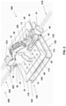
- Figure 1 shows a schematic view of an arrangement of the tensioner 300 of a mooring line 400 of a floating structure 500 of the invention, wherein the tensioner 300 is arranged close to an anchoring device 600, which can interchangeably be an anchor or a pile, and is secured to the seabed 700.
- the mooring line 400 comprises a first mooring line 410 formed by a chain, with a first end 411 of the chain being attached to the anchoring device 600 and a second end 412 passing through the tensioner 300 and being attached to a rope coming from a vessel 900 used for pulling the first mooring line through the rope, and thereby pulling and tautening the mooring line 400.
- Said mooring line 400 further comprises a second mooring line 420 separate from the first mooring line 410.
- This second mooring line 420 is formed by a rope segment and a chain segment, the second mooring line 420 comprising a first end 421 which consists of rope and is attached to the floating structure 500, and a second end 422 which consists of chain and is attached to the tensioner 300.
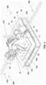
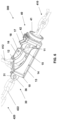
- FIG. 2 shows a perspective view of an embodiment of the tensioner 300 of the mooring line 400 of a floating structure 500, comprising separate first and second mooring lines 410 and 420 with the tensioner 300.
- Said tensioner 300 comprises an elongated body 10 with a base 13 and a longitudinal housing 11 configured for housing a chain segment of the first mooring line 410.
- the body 10 comprises, attached thereto, a connection unit 30 at one of its ends, said connection unit 30 comprising a connector member 31 which is configured for attaching a second end 422 of the second mooring line 420 to the body 10.
- the body 10 also comprises, attached at the other end, an inlet unit 40 which is configured for inserting a second end 412 of the first mooring line 410 into the housing 11 of the body 10.
- the body 10 comprises an opening 12 in the upper part for the passage of the second end 412 of the first mooring line 410 from the inlet unit 40, which passes through the longitudinal housing 11, and exits through the opening 12 along a direction changing element.
- This direction changing element allows diverting the second chain end 412 from the inlet direction in the inlet unit 40, towards the pulling direction defined by the ship 900 on the surface of the water.
- Said tensioner 300 comprises a stabilizing platform 100 for the purpose of keeping the tensioner 300 as stable as possible. To that end, the body 10 of the tensioner 300 is fixed to the stabilizing platform 100. Once the stabilizing platform 100 is fixed to the tensioner 300, said stabilizing platform 100 projects laterally from said body 10.
- the tensioner 300 comprises a direction changing element, which is a sheave 20, and a stabilizing platform 100 comprising a plate 110 and a structure 120
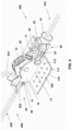
- Figure 3 shows a second perspective view of the tensioner 300 of Figure 2 .
- the body 10 of this embodiment of the tensioner 300 is formed by two separate, parallel and elongated vertical plates fixed to the horizontal base 13, with the longitudinal housing 11 being the space configured between the two vertical plates and the horizontal base 13, which allows housing the sheave 20 which is rotatably coupled to said vertical plates, and the chain segment of the first mooring line 410.
- This chain segment is the second end 412 which, after being guided into the housing 11 by a guide arranged on the inner face of the base 13 (not shown in the drawings), is supported in the sheave 20, which provides an outlet in the direction of the ship 900 from where said segment is being pulled.
- the stabilizing platform 100 comprises a plate 110 on which the body 10 is arranged.
- This plate 110 which projects laterally from the body 10, comprises a plurality of through holes 112. The function of these holes 112 is to prevent sand or other elements existing in the water 800 from building up in the stabilizing platform 100.
- the plate may not be a horizontal plate, but rather it may be formed by a set of attached plates forming different angles with one another.
- the stabilizing platform 100 of the tensioner 300 of the embodiment that is shown further comprises a structure 120.
- this structure 120 comprises two plates 130, an upper plate and another lower plate, which are superimposed on and separate from one another by a certain distance. To maintain this separation distance, the two plates 130 are attached by four vertical profiles 140, which allows said plates 130 to be parallel to one another.
- the structure may comprise a larger number of plates, and/or it may comprise another number of profiles attaching the plates to one another, for example two, and/or the plates of the structure are not parallel, being attached in that case by means of profiles having different dimensions.
- the plate 110 is fixed, for example by means of welding or by means of screws, to the upper plate 130 of the structure 120.
- Each of the two upper and lower plates 130 comprises a plurality of through holes 131 on the surface thereof, such that sand or other elements in the water built up in the stabilizing platform 100 may be discharged through the through holes 112 of the plate 110 and through the through holes 131 of the plates 130 of the structure 120 of the stabilizing platform 100.
- the profiles 140 that allow the plates 130 of the structure 120 to be attached to one another demarcate closed contours.
- the four vertical profiles 140 close the space existing between the two horizontal plates 130.
- the profiles 140 each comprise an elongated horizontal opening 142.
- FIG 8 shows a perspective view of an embodiment of the stabilizing platform 100 of the tensioner 300 of the invention, wherein said stabilizing platform 100 comprises a plate 110 and a structure 120 like those shown in Figures 2 and 3 of the embodiment of the tensioner 300.
- the structure 120 comprises four vertical plates 122 which are arranged fixed on the edges of each of the sides of the lower plate 130, said vertical plates 122 projecting downwards from said lower plate 130.
- the essential function of said vertical plates 122 is carried out when the tensioner 300 is arranged next to the anchoring device 600, and after the mooring line 400 has been tensioned, said tensioner 300 is supported on the seabed 700.
- the vertical plates 122 are driven into said seabed 700, which helps the tensioner 300 to remain immobile and more stable.
- the structure 120 comprises four connector members 121 which are arranged fixed in each of the vertices of the upper plate 130.
- the function of said connector members 121 is to allow the connection to different pulling ropes, which in turn allow moving, in or out of the water, the tensioner 300 or the stabilizing platform 100 separately.
- the body 10 and the stabilizing platform 100 of the tensioner 300 can be fixed by means of welding, so they would form a single part, but the tensioner 300 may also comprise coupling means 150 for coupling the body 10 and the stabilizing platform 100, as in the case of the embodiment of the tensioner shown in Figures 2 and 3 .
- the coupling means 150 are two brackets arranged on each side of the body 10, with one face being supported on said body 10 and the other face being supported on the plate 110 of the stabilizing platform 100.
- the attachment is by means of screws which are concealed and which are arranged going through the vertical walls of the body 10 and in the plate 110, and they are housed in threaded holes arranged in the brackets of the coupling means 150.
- the body 10 and the stabilizing platform 100 are thereby made separable, thereby making it easier to transport and assemble the tensioner 300.
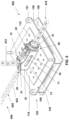
- Figure 4 shows a perspective view of a second embodiment of the tensioner 300 of a mooring line 400 of a floating structure 500 of the invention, wherein the tensioner 300 also comprises a sheave 20 like in the first embodiment, but in this second embodiment the stabilizing platform 100 comprises only one plate 110.
- the remaining features of the tensioner 300 are the same in the first and second embodiments.
- the sheave 20 allows arranging the second end 412 of the first mooring line 410 at an angle of the outlet direction as pulled from the ship 900 that is greater than 90°, which allows providing greater flexibility when tautening the mooring line 400.
- the second embodiment of the tensioner 400 is more lightweight and less expensive.
- connection unit 30 and the inlet unit 40 are common features of the first and second embodiments of the tensioner 300.
- the connection unit 30 comprises, in addition to the connector member 31, a guiding and protection device 32 comprising a support surface for the second end 412 of the first mooring line 410 when it is not in use.
- Said guiding and protection device 32 is arranged fixed to a vertical wall of the body 10, closing one end of the vertical walls forming the body 10, and therefore closing the longitudinal housing 11 of said body 10.
- the connector member 31 is fixed to said vertical wall and the guiding and protection device 32 is axially projected over said connector member 31 in the body 10.
- This guiding and protection device 32 comprises a cradle 33, followed by a V-shaped wedge 34, and a downwardly inclined outlet ramp 35, forming the support surface for the second end 412.
- the inlet unit 40 comprises a cross-shaped inlet element 41, i.e., a hollow, frustoconical-shaped part which internally comprises a wall with a hole in the shape of a cross, and having dimensions suited to the size of the horizontal and vertical links of the chain forming the second end 412 of the first mooring line 410.
- the inlet unit 40 After the inlet element 41, and in the direction of insertion of the second end 412, the inlet unit 40 comprises a retaining device 42 for retaining the chain. This retaining device 42 is coupled to the inlet element 41 and is rotatable in a vertical plane.
- the retaining device 42 comprises a rotatable vertical wall comprising on its inner face a through hole for the vertical links of the chain, and a notch on said face on the sides of the through hole, and having the dimensions and being in the position of the horizontal links of the chain. Therefore, when the second end 412 is pulled, the links of the chain go through and are guided into the inlet element 41, and as the horizontal links pass through the retaining device 42, they lift up said retaining device 42, making it rotate. When the mooring line 400 has been tensioned, the second end 412 of the first mooring line 410 is released. In order for the chain not to slip backwards, the horizontal link of said chain that is next to the retaining device 42 is retained by the notch of the inner face of the rotatable vertical wall.
- the inlet unit 40 of these first and second embodiments of the tensioner 300 comprises a tilting device 43, which is coupled in a vertically rotatable manner to the vertical walls of the body 10 on a rotating shaft 44.
- the tilting device 43 comprises an inclinometer 45 which is arranged on one side and used to measure the angle that the tilting device 43 rotates, and a limiter 46 which is arranged on the rotating shaft 44 for limiting rotation and used to limit the rotation of the tilting device 43 at a given angle.
- the inlet element 41 and the retaining device 42 of the inlet unit 40 are arranged assembled in the tilting device 43, such that the inclinometer 45 measures the angle that the second end 412 of the first mooring line 410 is being rotated while the mooring line 400 is being tensioned, this being an indirect way to calculate the tension obtained in the mooring line 400.
- the limiter 46 allows limiting the angle at which the second end 412 is arranged with respect to the plane of the base 13 of the body 10 of the tensioner 300.
- Figure 5 shows a perspective view of a third embodiment of the tensioner 300 of a mooring line 400 of a floating structure 500 of the invention, wherein the tensioner 300 comprises a body 10 with a curved upper wall 16, and a stabilizing platform 100 comprising a plate 110 and a structure 120.
- Figure 6 shows a perspective section view of the tensioner 300 of Figure 5 without the stabilizing platform 100, showing the internal guiding of the second end 412 of the first mooring line 410.
- the body 10 of this embodiment of the tensioner 300 is a substantially prismatic body, with a horizontal base 13, two separate, parallel and elongated vertical walls fixed to the horizontal base 13, a vertical wall at one end wherein the connection unit 30 is attached to the connector member 31, an opposite end wherein the inlet unit 40 is coupled, and the curved upper wall 16.
- the longitudinal housing 11 is the space configured between the two vertical walls, the horizontal base 13, and the upper wall 16.
- the direction changing element is, as shown in detail in Figure 7 , the curved upper wall 16.
- Said upper wall 16 comprises on its inner face a guide 17 for the vertical links of the second end 412 of the first mooring line 410, and comprises on its outer face, in a vertical wall, a through hole 18 which is used for transporting and/or for holding the tensioner 300 from a ship with a rope attached to said hole 18 while the mooring line 400 is tensioned.
- the base 13 comprises on its inner face a guide 15 for the vertical links of the second end 412, and it is arranged opposite guide 17, such that the second end 412 is guided with guides 15 and 17 and exits through an opening 12 of the housing 11 arranged where the curved upper wall 16 ends.
- the curved upper wall 16 allows arranging the second end 412 of the first mooring line 410 at an angle of the outlet direction as pulled from the ship 900 that is less than 90°, which gives the tensioner 300 better qualities for being arranged fixed directly to the floating structure 500.
- the base 13 of the body 10 is fixed to the stabilizing platform 100, but in other embodiments of the tensioner the stabilizing platform can be fixed on one side of the body, for example.
- the base 13 comprises a plurality of through holes 14, just like the base 13 of the body 10 of the tensioners 300 of the first and second embodiments (not shown in the drawings). Sand or other elements in the water that may be retained inside the body 10 can thereby be discharged by means of the through holes 14 of the base 13, and they can then be discharged from the stabilizing platform 100 by means of the through holes 112 of the plate 110, the through holes 131 of the vertical plates 130, and the openings 142 of the profiles 140 of the structure 120.
- the features of the stabilizing platform 100 are the same as those described for the first and second embodiments of the tensioner 300.
- the direction changing element for the second end 412 of the first mooring line 410 is protected against direct impacts of other elements, and at the same time, and especially when the tensioner is arranged next to the anchoring device 600 on the seabed 700, said direction changing element is more visible for the maneuvers to be carried out in the water 800.
- connection unit 30 comprises only the connector member 31, and the inlet unit 40 comprises only the cross-shaped inlet element 41 and the retaining device 42 with the features described for the first and second embodiments of the tensioner 300.
- connection unit 30 of any of the three embodiments of the tensioner 300 that are shown comprises a connector member 31 where the second end 422 of the second mooring line 420 is attached.
- said connector member 31 there is arranged an assembly bolt in which there is arranged a load cell 36 for measuring the tension of the mooring line 400, such that it is possible to directly monitor the tension of said mooring line 400.
Landscapes
- Chemical & Material Sciences (AREA)
- Engineering & Computer Science (AREA)
- Combustion & Propulsion (AREA)
- Mechanical Engineering (AREA)
- Ocean & Marine Engineering (AREA)
- Bridges Or Land Bridges (AREA)
- Other Liquid Machine Or Engine Such As Wave Power Use (AREA)
- Cleaning Or Clearing Of The Surface Of Open Water (AREA)
- Tents Or Canopies (AREA)
- Devices Affording Protection Of Roads Or Walls For Sound Insulation (AREA)
- Laying Of Electric Cables Or Lines Outside (AREA)
Priority Applications (1)
| Application Number | Priority Date | Filing Date | Title |
|---|---|---|---|
| EP23175475.5A EP4242094A3 (fr) | 2018-03-02 | 2018-03-02 | Tendeur de ligne de fond d'une structure flottante |
Applications Claiming Priority (3)
| Application Number | Priority Date | Filing Date | Title |
|---|---|---|---|
| EP23175475.5A EP4242094A3 (fr) | 2018-03-02 | 2018-03-02 | Tendeur de ligne de fond d'une structure flottante |
| EP18721831.8A EP3760529B1 (fr) | 2018-03-02 | 2018-03-02 | Tendeur de ligne de fond d'une structure flottante |
| PCT/ES2018/070156 WO2019166674A1 (fr) | 2018-03-02 | 2018-03-02 | Tendeur de ligne de fond d'une structure flottante |
Related Parent Applications (2)
| Application Number | Title | Priority Date | Filing Date |
|---|---|---|---|
| EP18721831.8A Division EP3760529B1 (fr) | 2018-03-02 | 2018-03-02 | Tendeur de ligne de fond d'une structure flottante |
| EP18721831.8A Division-Into EP3760529B1 (fr) | 2018-03-02 | 2018-03-02 | Tendeur de ligne de fond d'une structure flottante |
Publications (2)
| Publication Number | Publication Date |
|---|---|
| EP4242094A2 true EP4242094A2 (fr) | 2023-09-13 |
| EP4242094A3 EP4242094A3 (fr) | 2023-11-08 |
Family
ID=62104320
Family Applications (2)
| Application Number | Title | Priority Date | Filing Date |
|---|---|---|---|
| EP23175475.5A Withdrawn EP4242094A3 (fr) | 2018-03-02 | 2018-03-02 | Tendeur de ligne de fond d'une structure flottante |
| EP18721831.8A Active EP3760529B1 (fr) | 2018-03-02 | 2018-03-02 | Tendeur de ligne de fond d'une structure flottante |
Family Applications After (1)
| Application Number | Title | Priority Date | Filing Date |
|---|---|---|---|
| EP18721831.8A Active EP3760529B1 (fr) | 2018-03-02 | 2018-03-02 | Tendeur de ligne de fond d'une structure flottante |
Country Status (6)
| Country | Link |
|---|---|
| US (1) | US11008072B2 (fr) |
| EP (2) | EP4242094A3 (fr) |
| CN (1) | CN112041222B (fr) |
| AU (1) | AU2018410756A1 (fr) |
| ES (1) | ES2956037T3 (fr) |
| WO (1) | WO2019166674A1 (fr) |
Families Citing this family (7)
| Publication number | Priority date | Publication date | Assignee | Title |
|---|---|---|---|---|
| WO2021262980A1 (fr) * | 2020-06-24 | 2021-12-30 | Bardex Corporation | Équipement d'amarrage destiné à être utilisé en tension en ligne |
| EP4101806B1 (fr) * | 2021-06-07 | 2025-03-19 | Vinci Construction Grands Projets | Equipement sous-marin pour la mise en tension de lignes d'ancrage d'une structure offshore et procédé d'installation d'un tel équipement |
| CN113371158B (zh) * | 2021-07-15 | 2024-05-24 | 烟台宏远载人压力舱工程技术研究院有限公司 | 一种多自由度脐带缆升沉补偿装置 |
| CN114228904B (zh) * | 2021-11-12 | 2023-03-28 | 华电重工股份有限公司 | 一种悬链线调节装置及系泊系统 |
| NO347289B1 (en) * | 2022-04-29 | 2023-08-28 | I P Huse As | A seabed tensioner, and a system and a method for mooring a floating structure |
| WO2024074742A1 (fr) | 2022-10-03 | 2024-04-11 | Vicinay Mooring Connectors, S.A. | Maillon de chaîne d'amarrage démontable, système de liaison et procédé pour décrocher deux chaînes d'amarrage sous l'eau |
| CN116714717A (zh) * | 2023-07-20 | 2023-09-08 | 中海石油(中国)有限公司 | 一种海上浮体系泊系统在海底预张紧的方法 |
Citations (2)
| Publication number | Priority date | Publication date | Assignee | Title |
|---|---|---|---|---|
| US20060060126A1 (en) * | 2001-06-15 | 2006-03-23 | Technip France | Method of and apparatus for offshore mooring |
| US20160185427A1 (en) | 2011-07-06 | 2016-06-30 | Single Buoy Moorings Inc. | Anchor line tensioning method |
Family Cites Families (25)
| Publication number | Priority date | Publication date | Assignee | Title |
|---|---|---|---|---|
| US3880105A (en) * | 1973-10-01 | 1975-04-29 | Offshore Co | Drilling vessel and drilling vessel mooring system and method |
| NO139775C (no) * | 1977-04-28 | 1979-06-06 | Pusnes Mek Verksted | Anordning ved kjettingstopper. |
| US4175620A (en) * | 1977-12-06 | 1979-11-27 | Brown & Root, Inc. | Methods and apparatus for anchoring offshore pipeline |
| US5934216A (en) * | 1997-09-16 | 1999-08-10 | Oceaneering International Inc. | Method and apparatus for tensioning and deploying mooring chain |
| NO984042A (no) * | 1998-09-03 | 1999-07-19 | Statoil Asa | Innretning for føring og stopping av en ankerkjetting på en flytende konstruksjon |
| WO2002087960A2 (fr) * | 2001-04-27 | 2002-11-07 | Conoco Inc | Plate-forme flottante presentant une amarre enroulable installee sur cette derniere et procede pour amarrer ladite plate-forme au moyen de cette amarre |
| EP1283158A1 (fr) * | 2001-08-06 | 2003-02-12 | Single Buoy Moorings Inc. | Procédé d'installation de ligne d'ancrage et connecteur associé |
| US7240633B2 (en) * | 2004-04-30 | 2007-07-10 | Timberland Equipment Limited | Underwater chain stopper and fairlead apparatus for anchoring offshore structures |
| DE102008027351A1 (de) * | 2008-06-07 | 2009-12-10 | Howaldtswerke-Deutsche Werft Gmbh | Unterseeboot |
| FR2934635B1 (fr) * | 2008-07-29 | 2010-08-13 | Technip France | Installation de conduite montante flexible de transport d'hydrocarbures pour grande profondeur |
| AU2011258073B2 (en) * | 2010-05-28 | 2015-07-09 | Lockheed Martin Corporation | Undersea anchoring system and method |
| FR2984272B1 (fr) * | 2011-12-14 | 2014-06-13 | Nov Blm | Chaumard pour le guidage d'une chaine d'ancrage, destine a equiper une installation d'ancrage au sol d'une plateforme flottante |
| US20140069657A1 (en) * | 2012-09-11 | 2014-03-13 | Oil States Industries, Inc. | Freestanding Hybrid Riser System Including a Bottom Configuration with a Flexible Pipe Joint and a Diverless Pipe Connector |
| NO335406B1 (no) * | 2012-11-27 | 2014-12-08 | Aker Engineering & Technology | System for undervanns sammenkobling |
| WO2015039483A1 (fr) * | 2013-09-22 | 2015-03-26 | 曲言明 | Système d'amarrage à poulie à bouée immergée |
| CN103482026B (zh) * | 2013-09-22 | 2015-10-28 | 江苏科技大学 | 一种用于超深水浮式结构物的混合式系泊系统及系泊方法 |
| FR3013312B1 (fr) * | 2013-11-15 | 2016-01-08 | Dcns | Chaumard de guidage d'un element d'ancrage |
| CN103640672A (zh) * | 2013-11-25 | 2014-03-19 | 无锡起岸重工机械有限公司 | 船用掣链器 |
| WO2016033278A1 (fr) * | 2014-08-27 | 2016-03-03 | Safe Marine Transfer, LLC | Procédé à vaisseaux multiples pour installer et récupérer des cargaisons d'équipement sous-marins |
| US20160085427A1 (en) | 2014-09-19 | 2016-03-24 | Caterpillar Inc. | System and method of sharing spatial data |
| US10184589B2 (en) * | 2015-03-04 | 2019-01-22 | Ge Oil & Gas Uk Limited | Riser assembly and method |
| FR3049924B1 (fr) * | 2016-04-11 | 2018-05-04 | Dcns | Structure offshore comportant au moins un chaumard |
| NO343765B1 (en) * | 2016-06-03 | 2019-06-03 | Scana Offshore Vestby As | Mooring pulley tensioning system |
| GB2551379B (en) * | 2016-06-16 | 2018-12-12 | Acergy France SAS | Upgrading subsea foundations of mooring systems |
| US10780952B1 (en) * | 2019-06-20 | 2020-09-22 | Hotwire Development, Llc | Bladder anchor system |
-
2018
- 2018-03-02 ES ES18721831T patent/ES2956037T3/es active Active
- 2018-03-02 CN CN201880090511.3A patent/CN112041222B/zh active Active
- 2018-03-02 WO PCT/ES2018/070156 patent/WO2019166674A1/fr not_active Ceased
- 2018-03-02 EP EP23175475.5A patent/EP4242094A3/fr not_active Withdrawn
- 2018-03-02 EP EP18721831.8A patent/EP3760529B1/fr active Active
- 2018-03-02 AU AU2018410756A patent/AU2018410756A1/en not_active Abandoned
-
2020
- 2020-08-06 US US16/986,496 patent/US11008072B2/en active Active
Patent Citations (2)
| Publication number | Priority date | Publication date | Assignee | Title |
|---|---|---|---|---|
| US20060060126A1 (en) * | 2001-06-15 | 2006-03-23 | Technip France | Method of and apparatus for offshore mooring |
| US20160185427A1 (en) | 2011-07-06 | 2016-06-30 | Single Buoy Moorings Inc. | Anchor line tensioning method |
Also Published As
| Publication number | Publication date |
|---|---|
| EP4242094A3 (fr) | 2023-11-08 |
| CN112041222B (zh) | 2022-10-04 |
| ES2956037T3 (es) | 2023-12-12 |
| BR112020016877A2 (pt) | 2020-12-15 |
| CN112041222A (zh) | 2020-12-04 |
| US20200377178A1 (en) | 2020-12-03 |
| BR112020016877A8 (pt) | 2022-10-04 |
| WO2019166674A1 (fr) | 2019-09-06 |
| EP3760529B1 (fr) | 2023-07-05 |
| US11008072B2 (en) | 2021-05-18 |
| AU2018410756A1 (en) | 2020-09-24 |
| EP3760529A1 (fr) | 2021-01-06 |
Similar Documents
| Publication | Publication Date | Title |
|---|---|---|
| US11008072B2 (en) | Tensioner of a mooring line of a floating structure | |
| KR101592130B1 (ko) | 부체식 풍력 발전 장치 | |
| US8915205B2 (en) | Fairlead latch device | |
| US5845893A (en) | Underwater self-aligning fairlead latch device for mooring a structure at sea | |
| US7140599B1 (en) | Coupling systems and methods for marine barriers | |
| ES3051837T3 (en) | Improved mooring/tensioning apparatus | |
| KR20060089730A (ko) | 일체형 체인 스토퍼를 갖는 페어리드 | |
| BR112013018223B1 (pt) | Contêiner marítimo que pode ser fechado em todos os lados | |
| US9233736B2 (en) | Installation for anchoring a floating platform to the ground | |
| KR20150065442A (ko) | 이동식 계류 장치 및 이를 구비한 선박 | |
| KR101644344B1 (ko) | 해양구조물용 난간 | |
| KR20180038700A (ko) | 회전 계선주가 구비되는 선박의 계류구조 및 이를 이용한 선박 계류방법 | |
| KR20180002424U (ko) | 선박용 승하선 장치 | |
| US20120186506A1 (en) | System for handling conventional and synthetic moorings lines, cables and the like aboard a vessel | |
| BR112020016877B1 (pt) | Tensionador de um cabo de amarração de uma estrutura flutuante | |
| US5297499A (en) | Cleat for securing a boat to a docking structure | |
| JP7853868B2 (ja) | 緊張係留浮体の設置方法および緊張係留浮体の設置構造 | |
| KR20220026931A (ko) | 부유식 안벽 계류장치 및 이를 이용한 시스템 | |
| KR100988124B1 (ko) | 스트랜드 잭을 이용한 계류 장치 | |
| JP4939856B2 (ja) | 係留システムと係留方法 | |
| US20090013918A1 (en) | Mooring Pull-In System | |
| KR20150003976U (ko) | 헬리데크의 안전장치 | |
| KR19990034073U (ko) | 해상공사용 재료투하수단이 구비된 바지선 | |
| KR200328378Y1 (ko) | 선박 예인장치 | |
| KR20150004591U (ko) | 갱웨이 보관장치 |
Legal Events
| Date | Code | Title | Description |
|---|---|---|---|
| PUAI | Public reference made under article 153(3) epc to a published international application that has entered the european phase |
Free format text: ORIGINAL CODE: 0009012 |
|
| STAA | Information on the status of an ep patent application or granted ep patent |
Free format text: STATUS: THE APPLICATION HAS BEEN PUBLISHED |
|
| AC | Divisional application: reference to earlier application |
Ref document number: 3760529 Country of ref document: EP Kind code of ref document: P |
|
| AK | Designated contracting states |
Kind code of ref document: A2 Designated state(s): AL AT BE BG CH CY CZ DE DK EE ES FI FR GB GR HR HU IE IS IT LI LT LU LV MC MK MT NL NO PL PT RO RS SE SI SK SM TR |
|
| PUAL | Search report despatched |
Free format text: ORIGINAL CODE: 0009013 |
|
| AK | Designated contracting states |
Kind code of ref document: A3 Designated state(s): AL AT BE BG CH CY CZ DE DK EE ES FI FR GB GR HR HU IE IS IT LI LT LU LV MC MK MT NL NO PL PT RO RS SE SI SK SM TR |
|
| RIC1 | Information provided on ipc code assigned before grant |
Ipc: B63B 21/50 20060101AFI20231004BHEP |
|
| STAA | Information on the status of an ep patent application or granted ep patent |
Free format text: STATUS: REQUEST FOR EXAMINATION WAS MADE |
|
| 17P | Request for examination filed |
Effective date: 20240508 |
|
| RBV | Designated contracting states (corrected) |
Designated state(s): AL AT BE BG CH CY CZ DE DK EE ES FI FR GB GR HR HU IE IS IT LI LT LU LV MC MK MT NL NO PL PT RO RS SE SI SK SM TR |
|
| STAA | Information on the status of an ep patent application or granted ep patent |
Free format text: STATUS: EXAMINATION IS IN PROGRESS |
|
| 17Q | First examination report despatched |
Effective date: 20250520 |
|
| STAA | Information on the status of an ep patent application or granted ep patent |
Free format text: STATUS: THE APPLICATION IS DEEMED TO BE WITHDRAWN |
|
| 18D | Application deemed to be withdrawn |
Effective date: 20251121 |