EP4242500A1 - Schieberventil - Google Patents
Schieberventil Download PDFInfo
- Publication number
- EP4242500A1 EP4242500A1 EP21889068.9A EP21889068A EP4242500A1 EP 4242500 A1 EP4242500 A1 EP 4242500A1 EP 21889068 A EP21889068 A EP 21889068A EP 4242500 A1 EP4242500 A1 EP 4242500A1
- Authority
- EP
- European Patent Office
- Prior art keywords
- depression
- land
- spool
- sleeve
- fluid
- Prior art date
- Legal status (The legal status is an assumption and is not a legal conclusion. Google has not performed a legal analysis and makes no representation as to the accuracy of the status listed.)
- Pending
Links
- 239000012530 fluid Substances 0.000 claims description 72
- 230000002093 peripheral effect Effects 0.000 description 26
- 238000005461 lubrication Methods 0.000 description 11
- 239000011247 coating layer Substances 0.000 description 6
- 230000029058 respiratory gaseous exchange Effects 0.000 description 5
- 239000011248 coating agent Substances 0.000 description 3
- 238000000576 coating method Methods 0.000 description 3
- 239000007788 liquid Substances 0.000 description 3
- OKTJSMMVPCPJKN-UHFFFAOYSA-N Carbon Chemical compound [C] OKTJSMMVPCPJKN-UHFFFAOYSA-N 0.000 description 1
- 238000007792 addition Methods 0.000 description 1
- 229910052799 carbon Inorganic materials 0.000 description 1
- 238000005260 corrosion Methods 0.000 description 1
- 230000007797 corrosion Effects 0.000 description 1
- 239000000463 material Substances 0.000 description 1
- 239000007769 metal material Substances 0.000 description 1
- 238000000034 method Methods 0.000 description 1
- 238000012986 modification Methods 0.000 description 1
- 230000004048 modification Effects 0.000 description 1
- CWQXQMHSOZUFJS-UHFFFAOYSA-N molybdenum disulfide Chemical compound S=[Mo]=S CWQXQMHSOZUFJS-UHFFFAOYSA-N 0.000 description 1
- 229910052982 molybdenum disulfide Inorganic materials 0.000 description 1
- 230000010363 phase shift Effects 0.000 description 1
- 238000007747 plating Methods 0.000 description 1
- 239000011347 resin Substances 0.000 description 1
- 229920005989 resin Polymers 0.000 description 1
- 230000000717 retained effect Effects 0.000 description 1
Images




Classifications
-
- F—MECHANICAL ENGINEERING; LIGHTING; HEATING; WEAPONS; BLASTING
- F16—ENGINEERING ELEMENTS AND UNITS; GENERAL MEASURES FOR PRODUCING AND MAINTAINING EFFECTIVE FUNCTIONING OF MACHINES OR INSTALLATIONS; THERMAL INSULATION IN GENERAL
- F16K—VALVES; TAPS; COCKS; ACTUATING-FLOATS; DEVICES FOR VENTING OR AERATING
- F16K31/00—Actuating devices; Operating means; Releasing devices
- F16K31/02—Actuating devices; Operating means; Releasing devices electric; magnetic
- F16K31/06—Actuating devices; Operating means; Releasing devices electric; magnetic using a magnet, e.g. diaphragm valves, cutting off by means of a liquid
- F16K31/0603—Multiple-way valves
- F16K31/061—Sliding valves
- F16K31/0613—Sliding valves with cylindrical slides
-
- F—MECHANICAL ENGINEERING; LIGHTING; HEATING; WEAPONS; BLASTING
- F16—ENGINEERING ELEMENTS AND UNITS; GENERAL MEASURES FOR PRODUCING AND MAINTAINING EFFECTIVE FUNCTIONING OF MACHINES OR INSTALLATIONS; THERMAL INSULATION IN GENERAL
- F16K—VALVES; TAPS; COCKS; ACTUATING-FLOATS; DEVICES FOR VENTING OR AERATING
- F16K11/00—Multiple-way valves, e.g. mixing valves; Pipe fittings incorporating such valves
- F16K11/02—Multiple-way valves, e.g. mixing valves; Pipe fittings incorporating such valves with all movable sealing faces moving as one unit
- F16K11/06—Multiple-way valves, e.g. mixing valves; Pipe fittings incorporating such valves with all movable sealing faces moving as one unit comprising only sliding valves, i.e. sliding closure elements
- F16K11/065—Multiple-way valves, e.g. mixing valves; Pipe fittings incorporating such valves with all movable sealing faces moving as one unit comprising only sliding valves, i.e. sliding closure elements with linearly sliding closure members
- F16K11/07—Multiple-way valves, e.g. mixing valves; Pipe fittings incorporating such valves with all movable sealing faces moving as one unit comprising only sliding valves, i.e. sliding closure elements with linearly sliding closure members with cylindrical slides
-
- F—MECHANICAL ENGINEERING; LIGHTING; HEATING; WEAPONS; BLASTING
- F16—ENGINEERING ELEMENTS AND UNITS; GENERAL MEASURES FOR PRODUCING AND MAINTAINING EFFECTIVE FUNCTIONING OF MACHINES OR INSTALLATIONS; THERMAL INSULATION IN GENERAL
- F16K—VALVES; TAPS; COCKS; ACTUATING-FLOATS; DEVICES FOR VENTING OR AERATING
- F16K11/00—Multiple-way valves, e.g. mixing valves; Pipe fittings incorporating such valves
- F16K11/02—Multiple-way valves, e.g. mixing valves; Pipe fittings incorporating such valves with all movable sealing faces moving as one unit
- F16K11/06—Multiple-way valves, e.g. mixing valves; Pipe fittings incorporating such valves with all movable sealing faces moving as one unit comprising only sliding valves, i.e. sliding closure elements
- F16K11/065—Multiple-way valves, e.g. mixing valves; Pipe fittings incorporating such valves with all movable sealing faces moving as one unit comprising only sliding valves, i.e. sliding closure elements with linearly sliding closure members
- F16K11/07—Multiple-way valves, e.g. mixing valves; Pipe fittings incorporating such valves with all movable sealing faces moving as one unit comprising only sliding valves, i.e. sliding closure elements with linearly sliding closure members with cylindrical slides
- F16K11/0708—Multiple-way valves, e.g. mixing valves; Pipe fittings incorporating such valves with all movable sealing faces moving as one unit comprising only sliding valves, i.e. sliding closure elements with linearly sliding closure members with cylindrical slides comprising means to avoid jamming of the slide or means to modify the flow
-
- Y—GENERAL TAGGING OF NEW TECHNOLOGICAL DEVELOPMENTS; GENERAL TAGGING OF CROSS-SECTIONAL TECHNOLOGIES SPANNING OVER SEVERAL SECTIONS OF THE IPC; TECHNICAL SUBJECTS COVERED BY FORMER USPC CROSS-REFERENCE ART COLLECTIONS [XRACs] AND DIGESTS
- Y10—TECHNICAL SUBJECTS COVERED BY FORMER USPC
- Y10T—TECHNICAL SUBJECTS COVERED BY FORMER US CLASSIFICATION
- Y10T137/00—Fluid handling
- Y10T137/8593—Systems
- Y10T137/86493—Multi-way valve unit
- Y10T137/86574—Supply and exhaust
- Y10T137/8667—Reciprocating valve
- Y10T137/86694—Piston valve
- Y10T137/8671—With annular passage [e.g., spool]
Definitions
- the present invention relates to a spool valve suitable for fluid control.
- valves suitable for controlling fluid are capable of controlling the pressure and flow rate of fluid by adjusting the degree of opening of the valve due to the movement of a valve body.
- Typical types of such valves include the spool type in which the valve body moves in parallel to an opening, which is a valve seat, and the lift type in which the valve body moves perpendicular to an opening, which is a valve seat.
- the spool type has the advantage of being able to handle a wide range of fluid pressures without exerting force from the fluid in the moving direction of a spool, which is a valve body, and the advantage of being able to easily configure a multi-port structure.
- a spool valve described in Patent Citation 1 which is an example of such a spool valve, has a spool driven in an axial direction by a solenoid and extending through a cylindrical sleeve with steps on the inner side.
- the spool has a plurality of lands, and the lands move in sliding contact with the inner wall of the sleeve. Further, the sleeve is provided with an inlet port and an outlet port.
- the solenoid When the solenoid is not energized, one of the lands faces the inlet port, the inlet port is closed by said land, and the valve is in a closed state in which the flow of fluid from the inlet port to the outlet port is blocked. Further, when the solenoid is energized, the driving force of the solenoid causes the spool to move in the axial direction against the biasing force of the coil spring, and the valve is brought into an open state in which the flow of fluid from the inlet port to the outlet port is allowed.
- Patent Citation 1 JP 2014-163478 A (Pages 4, 5, FIG. 1 )
- the spool valve described in Patent Citation 1 can control the pressure and flow rate of the fluid by adjusting the amount of energization to the solenoid and adjusting the degree of opening of the valve according to said amount of energization.
- the valve when the valve is switched from the closed state to the open state, for example, the flow of fluid from the inlet port to the outlet port occurs, and high-pressure fluid flows through the inlet port, which may result in a force that transiently moves the spool in a radial direction.
- the spool may be slightly tilted or deformed to cause the land to bite into the inner wall of the sleeve, causing a hydraulic lock. Accordingly, the smooth movement of the spool may be hindered.
- the present invention has been made in view of such problems, and an object of the present invention is to provide a spool valve capable of stably moving a spool in an axial direction.
- a spool valve includes: a sleeve having a plurality of ports; and a spool arranged inside the sleeve and including a land formed so as to be brought into sliding contact with an inner wall of the sleeve, wherein a depression is formed over an entire circumference in at least one of the land and the inner wall of the sleeve with which the land is brought into sliding contact.
- the depression retains the fluid to maintain a good lubrication state between the land of the spool and the inner wall of the sleeve. Accordingly, the spool can be stably moved in the axial direction. Further, the fluid can be supplied between the inner wall of the sleeve and the land regardless of the circumferential position to improve the lubrication state between the land of the spool and the inner wall of the sleeve regardless of the circumferential position.
- the depression is formed of a plurality of depression portions, and at least one of the land and the inner wall of the sleeve with which the land is brought into sliding contact may have a load receiving portion between the adjacent depression portions, the load receiving portion being brought into sliding contact with the inner wall of the sleeve or the land.
- the load receiving portion being brought into sliding contact with the inner wall of the sleeve or the land.
- the depression extends in an axial direction.
- the fluid can be supplied to positions separated in the axial direction. Further, when a valve body moves, it is likely to communicate with any of the ports. In addition, when the valve body communicates with the port, the fluid can be supplied from said port to prevent the depletion of the fluid.
- the land faces an inlet port through which fluid flows into the sleeve.
- the depression is provided in at least one of the land facing the inlet port and the inner wall of the sleeve with which said land is brought into sliding contact, so that the land that is likely to be affected by the fluid and the inner wall of the sleeve with which said land is brought into sliding contact are kept well lubricated. Accordingly, the spool can be stably moved in the axial direction.
- the depression is in communication with an annular space which is in communication with the inlet port.
- the fluid that has flowed in from the inlet port is dispersed in the circumferential direction by the annular space, and the force that moves the spool in a radial direction is reduced. Accordingly, the land is less likely to bite into the inner wall of the sleeve, and a good lubrication state can be maintained between the land and the inner wall more stably.
- the depression is in communication with a storage groove in which fluid is stored. According to this preferable configuration, the fluid from the storage groove is also supplied to the depression, so that the fluid can be supplied more reliably.
- the depression is separated from opposite ends in the axial direction of a portion in which the depression is formed in at least one of the land and the inner wall of the sleeve with which the land is brought into sliding contact. According to this preferable configuration, the fluid in the depression is prevented from leaking to the adjacent space.
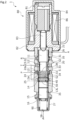
- a spool valve according to a first embodiment of the present invention will be described with reference to FIGS. 1 to FIG. 4 .
- the right and left sides as viewed from the front in FIG. 1 will be described as the right and left sides of the spool valve.
- the right side of the plane of paper on which a solenoid 80 is arranged will be described as the right side of the spool valve
- the left side of the plane of paper on which a coil spring 90 is arranged will be described as the left side of the spool valve.
- a depression may be illustrated with a dot-like texture.
- a spool valve 1 is a spool solenoid valve that adjusts the flow rate of oil.
- the fluid whose flow rate and the like are adjusted by the spool valve 1 is not limited to oil.
- the spool valve 1 mainly includes a spool 10, a sleeve 20, the solenoid 80, and the coil spring 90.
- the spool 10 is made of metal material or resin material.
- the spool 10 extends through the sleeve 20 so as to be movable in an axial direction.
- the solenoid 80 is connected to the sleeve 20 and exerts a driving force on the spool 10 in a valve open direction.
- the coil spring 90 is arranged within the sleeve 20 and exerts a biasing force on the spool 10 in a valve closing direction.
- the solenoid 80 mainly includes a casing 81, a stator 82 as a fixed core, a rod 83, a moving core 84, and an exciting coil 86.
- the stator 82 is part of the casing 81.
- the rod 83 extends through the casing 81 and is arranged so as to reciprocate in the axial direction.
- the moving core 84 extends through the casing 81 and transmits the driving force to the rod 83.
- the coil 86 is wound around the casing 81 via a bobbin.
- a leftward-facing T-shaped stator 82 is arranged at the left end portion of the casing 81.
- An axially rightward recessed recess is formed in the center of the left end portion of the stator 82.
- the right end portion of the sleeve 20 is press-fitted and fixed in the recess.
- the sleeve 20 is formed into a stepped cylindrical shape with a through hole 21 formed in the center in a radial direction and extending through the sleeve 20 in the axial direction.
- the sleeve 20 has a discharge port 22, an outlet port 23, an inlet port 24, and a feedback port 25 in order from the right in the axial direction.
- the discharge port 22 is in communication with an oil reservoir R.
- the outlet port 23 is in communication with a load T.
- the inlet port 24 is in communication with a hydraulic pump P.
- the feedback port 25 is in communication with the outlet port 23.
- Each of the ports 22 to 25 is a flow path extending mainly in the radial direction with respect to the through hole 21.
- first inner wall 31, a second inner wall 32, a third inner wall 33, a fourth inner wall 34 and a fifth inner wall 35 are formed on the inner diameter side of the sleeve 20.
- the first inner wall 31 protrudes radially inward on the right side of the discharge port 22 in the axial direction and is formed into an annular shape.
- the second inner wall 32 protrudes radially inward on the left side of the discharge port 22 in the axial direction and is formed into an annular shape.
- the third inner wall 33 protrudes radially inward on the left side of the outlet port 23 in the axial direction and is formed into an annular shape.
- the fourth inner wall 34 protrudes radially inward on the left side of the inlet port 24 in the axial direction and is formed into an annular shape.
- the fifth inner wall 35 protrudes radially inward on the left side of the feedback port 25 in the axial direction and is formed into an annular shape.
- a recess 24a is formed on the inner diameter side of the sleeve 20.
- the recess 24a is recessed radially outward between the third inner wall 33 and the fourth inner wall 34 and is formed into an annular shape.
- An annular space S is defined by the recess 24a and is in communication with the inlet port 24 and the through hole 21.
- the through hole 21 according to this embodiment is a cylindrical hole defined by the inner walls 31 to 35.
- the sleeve 20 has a breathing passage 26 formed on the right side of the first inner wall 31 in the axial direction and being in communication with an outside space A outside the sleeve 20.
- a retainer 27 that holds the coil spring 90 is caulked to the left end portion of the sleeve 20. Further, a breathing passage 28 is formed at the bottom of the retainer 27 and is in communication with the outside space A.
- the volume of the space between the solenoid 80 and the spool 10 and the volume of the space between the spool 10 and the retainer 27 change as the spool 10 moves. Since the breathing passages 26, 28 are in communication with the outside space A outside the sleeve 20, the fluid flows through breathing passages 26, 28 from the outside space A and flows through the breathing passages 26, 28 to the outside space A according to the change in volume. Accordingly, the pressure in the spaces is kept substantially the same.
- the spool 10 is formed into a columnar shape with steps on the outer diameter side.
- the outer peripheral surface of the spool 10 is coated with plating, diamond-like carbon (DLC), molybdenum disulfide, etc. for the purpose of improving slidability and preventing corrosion, to form a coating layer C (see FIG. 3 ).
- the coating layer C is exaggeratedly illustrated for convenience of explanation. Further, the coating layer C may be formed on the inner peripheral surface of the sleeve 20, and neither the spool 10 nor the sleeve 20 may be coated.
- the spool 10 has a first land 11, a first small diameter portion 12, a second land 13, a second small diameter portion 14, a third land 15, and a third small diameter portion 16 in order from the right in the axial direction.
- the first small diameter portion 12 is formed to have a smaller diameter than the first land 11.
- the second land 13 is formed to have a larger diameter than the first small diameter portion 12.
- the second small diameter portion 14 is formed to have a smaller diameter than the second land 13.
- the third land 15 is formed to have a larger diameter than the second small diameter portion 14.
- the third small diameter portion 16 is formed to have a smaller diameter than the third land 15.
- the first land 11 is arranged so as to be brought into sliding contact with the first inner wall 31 and the second inner wall 32.
- the second land 13 is arranged so as to be brought into sliding contact with the third inner wall 33 and the fourth inner wall 34.
- the third land 15 is arranged so as to be brought into sliding contact with the fifth inner wall 35.
- annular storage groove 40 and a ladder lottery-shaped depression 50 are formed in the second land 13.
- the storage groove 40 is a groove formed by cutting the second land 13 before coating into an annular shape over the circumference and then coating the surface of the second land 13.
- the depression 50 is a depression formed over the circumference of the coating layer C (see FIG. 3 ) of the spool 10.
- the depression 50 includes a plurality of axial depression portions 51 extending linearly in the axial direction and a plurality of peripheral depression portions 52 extending linearly in the circumferential direction.
- the axial depression portions 51 are arranged at predetermined intervals in the circumferential direction. Further, the opposite end portions of the axial depression portions 51 in the axial direction are separated from the right and left ends of the second land 13 in the axial direction, in other words, an end 13R on the side of the outlet port 23 and an end 13L on the side of the feedback port 25, and are closed in the axial direction.
- the axial depression portions 51 are in communication with the storage groove 40 formed at the left end portion thereof in the axial direction. More specifically, there are a portion in communication with the storage groove 40 from the side of the inlet port 24 and a portion in communication with the side of the end 13L of the second land 13 from the storage groove 40.
- the peripheral depression portions 52 are arranged at predetermined intervals in the axial direction. Further, the peripheral depression portions 52 adjacent to each other in the circumferential direction have different positions in the axial direction, and the peripheral depression portions 52 one apart from each other in the circumferential direction have the same position in the axial direction. That is, the depressions 50 have the specific patterns equiangularly arranged over an entire circumference.
- a depth dimension L1 of the storage groove 40 is sufficiently deeper than a depth dimension L2 of the axial depression portions 51 (L1 > L2).
- the depth dimension L1 of the storage groove 40 is set to 100 ⁇ m
- the depth dimension L2 of the axial depression portions 51 is set to 5 ⁇ m.
- the depth dimension of the peripheral depression portions 52 is substantially the same as the depth dimension of the axial depression portions 51.
- the depth dimension L1 is five times or more the depth dimension L2.
- the second land 13 has a large number of load receiving portions 13a surrounded by a pair of adjacent axial depression portions 51 and a pair of adjacent peripheral depression portions 52 and by a pair of adjacent axial depression portions 51 and one of the peripheral depression portions 52.
- the load receiving portions 13a slide on the inner walls 33, 34 of the sleeve 20.
- the spool 10 when the solenoid 80 is not energized, the spool 10 is moved to the right in the axial direction by the biasing force of the coil spring 90, so that the space between the second land 13 and the inner walls 33, 34 of the sleeve 20 is sealed. Accordingly, the valve is in a closed state in which the inflow of fluid from the inlet port 24 to the outlet port 23 is restricted. That is, the spool valve 1 is normally closed.
- the spool valve 1 may be normally open.
- the center portion of the depression 50 in the axial direction faces the annular space S
- the right side of the center portion in the axial direction and the left side of the center portion in the axial direction face the third inner wall 33 and the fourth inner wall 34, respectively. Since the center portion is exposed to the fluid in the annular space S, the fluid is also supplied to the portions facing the inner walls 33, 34 of the sleeve 20 along the axial depression portions 51 and the peripheral depression portions 52. That is, the fluid is supplied to positions separated from the inlet port 24 in the axial direction.
- the opposite end portions of the depression 50 in the axial direction are closed in the vicinity of the end 13R and the end 13L of the second land 13. Additionally, said portions face the inner walls 33, 34 of the sleeve 20, so that the fluid in the depression 50 is prevented from leaking to the outside of the second land 13.
- the storage groove 40 is in communication with the depression 50, the fluid is supplied from the inlet port 24 through the depression 50.
- the depression 50 is formed in the second land 13 facing the inlet port 24, and the fluid is supplied to the entire depression 50 in the valve closed state as described above. Accordingly, a good lubrication state is maintained between the second land 13 and the third inner wall 33, which is easily affected by the fluid. Further, a good lubrication state is maintained between the second land 13 and the inner walls 33, 34. Accordingly, the driving force required to move the spool 10 is reduced, and the spool 10 can be stably moved in the axial direction.
- the depression 50 is supplied with not only the fluid flowing from the inlet port 24 but also is supplied with the fluid from the storage groove 40 as the fluid in the depression 50 moves due to the movement of the spool 10. Accordingly, the fluid can be supplied more reliably.
- the pressure of the fluid that has flowed into the depression 50 may generate buoyancy.
- the fluid that has moved from the other axial depression portions 51 and the other peripheral depression portions 52 onto the load receiving portions 13a due to the movement of the spool 10 also flows, so that fluid is less likely to be depleted.
- the right half of the depression 50 in the axial direction faces the annular space S
- the left half in the axial direction located on the left side of the right half in the axial direction faces the fourth inner wall 34. Accordingly, the right half in the axial direction is exposed to the fluid in the annular space S, so that the fluid is also supplied to the left half in the axial direction facing the fourth inner wall 34 of the sleeve 20 along the axial depression portions 51 and the peripheral depression portions 52, that is, the fluid is supplied to a position separated from the inlet port 24 in the axial direction and facing the fourth inner wall 34.
- the storage groove 40 faces the fourth inner wall 34 both during non-energization (see FIG. 1 ), and during energization and when the valve opening is maximized (see FIG. 2 ), and is not in direct communication with the feedback port 25. Accordingly, the fluid in the storage groove 40 is prevented from being depleted.
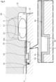
- a force that moves the spool 10 in the radial direction transiently may act as indicated by the white arrow in FIG. 4 , and the second land 13 may be pressed against the fourth inner wall 34 as indicated by the black arrow in FIG. 4 .
- the depression 50 retains the fluid, so that in the spool valve 1, a good lubrication state is maintained between the second land 13 and the inner walls 33, 34. Accordingly, the spool 10 can be stably moved axially leftward.
- the depression 50 is formed over the circumference, the lubrication state between the second land 13 and the fourth inner wall 34 can be improved regardless of the circumferential position.
- the spool 10 is supported against the inner walls 33, 34 of the sleeve 20 by the plurality of load receiving portions 13a formed on the second land 13, tilting or deformation of the spool 10 to a large extent is prevented.
- the left end portion of the depression 50 in the axial direction can communicate with the feedback port 25 to be supplied with the fluid from the feedback port 25. That is, the depression 50 extends in the axial direction, so that it is likely to communicate with the feedback port, and depletion of the fluid can be prevented.
- the peripheral depression portions 52 are arranged discontinuously in the circumferential direction, so that the fluid is less likely to move linearly compared to a configuration in which the depression is continuous in the circumferential direction. Accordingly, the fluid is likely to be retained in the entire circumference.
- annular space S in the valve closed state is an annular space defined by the recess 24a between the third inner wall 33 and the fourth inner wall 34 and the second land 13, the force acting from the fluid is likely to be dispersed in the circumferential direction at the time of switching from the valve closed state to the valve open state, reducing the force that transiently moves the spool 10 in the radial direction.
- the second land 13 is less likely to bite into the inner walls 33, 34 of the sleeve 20, and a good lubrication state can be more stably maintained between the second land 13 and the inner walls 33, 34.
- a depression 150 is formed in a second land 113 of a spool 110 of a spool valve 101.
- the depression 150 is composed of triangle wave shaped depression portions 151, 152 forming into a triangle wave shape and having the same amplitude and the same period with a phase shift of 180 degrees with respect to the circumferential direction. Further, the depression portions 151, 152 are in communication with each other at a plurality of locations in the circumferential direction. Further, the opposite end portions in the axial direction of the triangle wave shaped depression portions 151, 152 are separated from ends 113R, 113L of the second land 113 and are closed in the axial direction.
- the depression 150 is formed in a single diagonal check pattern.
- the depth dimension of the triangle wave shaped depression portions 151 and the triangle wave shaped depression portions 152 is substantially the same as the depth dimension L2 of each of the axial depression portions 51 and the peripheral depression portions 52 in the first embodiment.
- the second land 113 has a large number of load receiving portions 113a surrounded by the triangle wave shaped depression portions 151 and the triangle wave shaped depression portions 152.
- the load receiving portions 113a slide on the inner walls 33, 34 of the sleeve 20.
- the depression 150 not only retains the fluid but also is supplied with the fluid from the inlet port 24, so that a good lubrication state is maintained between the second land 113 and the inner walls 33, 34. Accordingly, the spool 110 can be stably moved axially leftward.
- the left end portion of the depression 150 in the axial direction can communicate with the feedback port 25 to receive fluid supply from the feedback port 25.
- the pressure of the fluid that has flowed into the depression 150 may generate buoyancy.
- the fluid that has moved from the other triangle wave shaped depression portions 151 and the other triangle wave shaped depression portions 152 onto the load receiving portions 113a due to the movement of the spool 110 also flows, so that fluid is less likely to be depleted.
- a plurality of dimples 250 is formed in a second land 213 of a spool 210 of a spool valve 201.
- the dimples 250 are depressions recessed in the shape of a part of a sphere.
- a load receiving portion 213a is formed around the dimples 250.
- the dimples 250 are separated from ends 213L, 213R of the second land 213.
- the dimples 250 may be recessed in a cylindrical shape, or may be recessed in a polygonal prism shape, and are not limited to have a shape of a part of a sphere.
- the depth dimension of the deepest portion of the dimple 250 is substantially the same as the depth dimension L2 of each of the axial depression portions 51 and the peripheral depression portions 52 in the first embodiment.
- the dimples 250 facing the annular space S in the valve closed state are supplied with fluid, and the dimples 250 retain the fluid in the valve closed state. Accordingly, a good lubrication state are maintained between the second land 213 and the inner walls 33, 34, and thus the spool 210 can be stably moved axially leftward.
- the dimples 250 located on the left side in the axial direction can communicate with the feedback port 25 to receive fluid supply from the feedback port 25.
- the pressure of the fluid that has flowed into the dimples 250 may generate buoyancy.
- a depression 350 is formed in the coating layer C of inner walls 133, 134 of a sleeve 120 and is composed of a plurality of axial depression portions 351 and a plurality of peripheral depression portions 352 and is in communication with the recess 24a.
- the depth dimension of the axial depression portions 351 and the peripheral depression portions 352 is substantially the same as the depth dimension L2 of each of the axial depression portions 51 and the peripheral depression portions 52 in the first embodiment.
- the inner walls 133, 134 has a large number of load receiving portions 133a, 134a surrounded by a pair of adjacent axial depression portions 351 and a pair of adjacent peripheral depression portions 352 and by a pair of adjacent axial depression portions 351 and one of the peripheral depression portions 352.
- the second land 313 of the spool 310 is brought into sliding contact with the load receiving portions 133a, 134a.
- the depression 350 not only retains the fluid but also is supplied with the fluid from the inlet port 24, so that a good lubrication state is maintained between the second land 313 and the inner walls 133, 134. Accordingly, the spool 310 can be stably moved axially leftward.
- the opposite end portions of the depression 350 in the axial direction are separated from ends 313L, 313R of the second land 313 in the valve closed state, and are not in communication with the outlet port 23 and the feedback port 25, preventing the fluid in the depression 350 from leaking to the outside of the second land 313.
- the pressure of the fluid that has flowed into the depression 350 may generate buoyancy.
- the fluid that has moved from the other axial depression portions 351 and the other peripheral depression portions 52 onto the load receiving portions 133a, 134a due to the movement of the spool 310 also flows, so that fluid is less likely to be depleted.
- the spool 310 is supported by the plurality of load receiving portions 133a, 134a formed on the inner walls 133, 134, preventing tilting or deformation of the spool 310 to a large extent.
- the spool valve has been described as being configured to be driven by a solenoid, but the present invention is not limited to this, and the spool valve may be driven manually, hydraulically, or by other methods.
- the depression has been described as being a depression having a shape of a ladder lottery, a depression having a diagonal check pattern, or the dimples, each of which is formed over the circumference, the present invention is not limited to this, and the depression may be a depression having a grid shape (see FIG. 8A ), a depression having a diagonal stripe pattern (see FIG. 8B ), or the like, each of which is formed over the circumference.
- a plurality of depressions having a plurality of L-shaped portions and inverted L-shaped portions extending in the circumferential direction from the axial depression portion may be arranged at predetermined intervals in the circumferential direction (see FIG. 8C ).
- a plurality of annular depressions that extend continuously in the circumferential direction may be spaced apart in the axial direction (see FIG. 8D ).
- a depression may be formed only in the portion that is brought into contact with the inner wall of the sleeve when the spool moves in the valve open direction (see FIG. 8E ).
- the shapes according to the first to third embodiments and the shapes illustrated in FIG. 8 may be combined, and may be changed as appropriate.
- the depression has been described as being formed in the second land facing the inlet port or in the inner wall of the sleeve communicating with the inlet port in the valve closed state, the present invention is not limited to this, and the depression may be formed in the land facing another port or in the inner wall of the sleeve communicating with another port.
- the depression has been described as being formed on the second land or on the third and fourth inner walls, the present invention is not limited to this, and the depression may be formed in both of them.
- the present invention is not limited to this, and the second land may directly face the inlet port.
- the depression formed in the inner walls of the sleeve may be in direct communication with the inlet port.
- the depression has been described as being formed in the coating layer, the present invention is not limited to this, and the depression may be formed directly in the spool or in the sleeve.
- a plurality of load receiving portions may be formed or only one load receiving portion may be formed.
- the storage groove has been described as being formed by being cut before coating and then being coated, but the present invention is not limited to this, and the storage groove may not be coated after being cut.
- the land has been described as having an annular storage groove, but the present invention is not limited to this, and the storage groove may not be formed.
- each of the ports has been described as a flow path extending mainly in the radial direction with respect to the through hole, the present invention is not limited to this, and each of the ports may be in communication with the through hole in the axial direction. That is, in the present invention, the spool valve is configured such that the land is provided so as to be able to slide on the inner wall regardless of the communication direction of the ports and a valve opening is adjusted by the land and the inner wall.
Landscapes
- Engineering & Computer Science (AREA)
- General Engineering & Computer Science (AREA)
- Mechanical Engineering (AREA)
- Sliding Valves (AREA)
- Multiple-Way Valves (AREA)
- Magnetically Actuated Valves (AREA)
Applications Claiming Priority (2)
| Application Number | Priority Date | Filing Date | Title |
|---|---|---|---|
| JP2020185375 | 2020-11-05 | ||
| PCT/JP2021/039230 WO2022097515A1 (ja) | 2020-11-05 | 2021-10-25 | スプール弁 |
Publications (2)
| Publication Number | Publication Date |
|---|---|
| EP4242500A1 true EP4242500A1 (de) | 2023-09-13 |
| EP4242500A4 EP4242500A4 (de) | 2024-10-09 |
Family
ID=81457825
Family Applications (1)
| Application Number | Title | Priority Date | Filing Date |
|---|---|---|---|
| EP21889068.9A Pending EP4242500A4 (de) | 2020-11-05 | 2021-10-25 | Schieberventil |
Country Status (5)
| Country | Link |
|---|---|
| US (1) | US12188573B2 (de) |
| EP (1) | EP4242500A4 (de) |
| JP (1) | JPWO2022097515A1 (de) |
| CN (1) | CN116420040A (de) |
| WO (1) | WO2022097515A1 (de) |
Families Citing this family (1)
| Publication number | Priority date | Publication date | Assignee | Title |
|---|---|---|---|---|
| EP4261441A1 (de) * | 2022-04-13 | 2023-10-18 | Sandvik Mining and Construction Oy | Steuerventil, schlagvorrichtung und verfahren |
Family Cites Families (16)
| Publication number | Priority date | Publication date | Assignee | Title |
|---|---|---|---|---|
| US4593719A (en) * | 1984-11-30 | 1986-06-10 | Leonard Willie B | Spool valve |
| JP2001263529A (ja) * | 2000-03-16 | 2001-09-26 | Mitsubishi Electric Corp | 電磁弁 |
| JP2002074000A (ja) | 2000-08-28 | 2002-03-12 | Sanwa Bank Ltd | 情報通信ネットワークを介した資金決済処理支援システム |
| WO2002018828A1 (en) | 2000-08-28 | 2002-03-07 | Nok Corporation | Solenoid valve |
| JP4572776B2 (ja) * | 2005-08-24 | 2010-11-04 | 株式会社デンソー | 流量制御弁 |
| JP4457827B2 (ja) * | 2004-09-24 | 2010-04-28 | 株式会社デンソー | 電磁弁 |
| JP4775362B2 (ja) * | 2007-11-09 | 2011-09-21 | 株式会社デンソー | スプール弁 |
| JP2014163478A (ja) | 2013-02-27 | 2014-09-08 | Keihin Corp | リニアソレノイドバルブ |
| US10100849B2 (en) * | 2014-06-23 | 2018-10-16 | Parker-Hannifin Corporation | Oil exchange in hydraulically operated and electro-hydraulically operated hydraulic valves |
| EP3201475B1 (de) * | 2014-09-29 | 2018-12-19 | Parker Hannifin Corporation | Mehrwegeventil |
| WO2016111391A1 (ko) * | 2015-01-08 | 2016-07-14 | 볼보 컨스트럭션 이큅먼트 에이비 | 건설기계용 유량 컨트롤밸브 |
| CA2939372A1 (en) * | 2015-08-20 | 2017-02-20 | Parker-Hannifin Corporation | Spool valve with special metering configuration for hydraulic valve main control speed |
| US10422437B2 (en) * | 2016-05-31 | 2019-09-24 | Komatsu Ltd | Spool valve, operation device, and work vehicle |
| JP6652008B2 (ja) * | 2016-07-21 | 2020-02-19 | 株式会社デンソー | スプール弁 |
| JP6955405B2 (ja) * | 2017-09-12 | 2021-10-27 | 川崎重工業株式会社 | スプール弁装置、及びスプール弁 |
| US11448313B2 (en) * | 2017-11-02 | 2022-09-20 | Superior Transmission Parts, Inc. | Pressure regulator valve |
-
2021
- 2021-10-25 JP JP2022560720A patent/JPWO2022097515A1/ja active Pending
- 2021-10-25 WO PCT/JP2021/039230 patent/WO2022097515A1/ja not_active Ceased
- 2021-10-25 CN CN202180074947.5A patent/CN116420040A/zh active Pending
- 2021-10-25 EP EP21889068.9A patent/EP4242500A4/de active Pending
- 2021-10-25 US US18/034,663 patent/US12188573B2/en active Active
Also Published As
| Publication number | Publication date |
|---|---|
| JPWO2022097515A1 (de) | 2022-05-12 |
| US20230392697A1 (en) | 2023-12-07 |
| EP4242500A4 (de) | 2024-10-09 |
| WO2022097515A1 (ja) | 2022-05-12 |
| CN116420040A (zh) | 2023-07-11 |
| US12188573B2 (en) | 2025-01-07 |
Similar Documents
| Publication | Publication Date | Title |
|---|---|---|
| JP5686201B2 (ja) | 電磁式リニア弁 | |
| JPH0336773Y2 (de) | ||
| US7503347B2 (en) | Linear solenoid valve | |
| JP5707386B2 (ja) | 小さなパッケージ空間を占める安定性向上特徴部を有するダイキャストスリーブ | |
| JP6094309B2 (ja) | ソレノイド駆動装置 | |
| JP2013100915A (ja) | 電磁弁 | |
| EP4242500A1 (de) | Schieberventil | |
| JP2019143781A (ja) | スプールバルブ | |
| JPH084937A (ja) | 流体制御弁 | |
| JP7463356B2 (ja) | ソレノイドバルブ | |
| KR102716498B1 (ko) | 솔레노이드 밸브 | |
| CN115183021A (zh) | 一种两位五通自停车电磁阀 | |
| JP2020193637A (ja) | ソレノイドバルブ | |
| JPH11141714A (ja) | 電磁弁 | |
| JPS62261782A (ja) | 電磁比例油圧制御弁 | |
| JP2005133880A (ja) | 電磁弁 | |
| JP7463355B2 (ja) | ソレノイドバルブ | |
| JPH084934A (ja) | 流体制御用電磁弁 | |
| US6883545B2 (en) | Three-way switching valve | |
| JP2010019319A (ja) | 電磁スプール弁装置 | |
| JPH0362921B2 (de) | ||
| JP7383907B2 (ja) | 電磁弁 | |
| JPH0814432A (ja) | 電磁スプール弁 | |
| US20210088153A1 (en) | Solenoid valve | |
| JP2005207461A (ja) | 電磁弁 |
Legal Events
| Date | Code | Title | Description |
|---|---|---|---|
| STAA | Information on the status of an ep patent application or granted ep patent |
Free format text: STATUS: THE INTERNATIONAL PUBLICATION HAS BEEN MADE |
|
| PUAI | Public reference made under article 153(3) epc to a published international application that has entered the european phase |
Free format text: ORIGINAL CODE: 0009012 |
|
| STAA | Information on the status of an ep patent application or granted ep patent |
Free format text: STATUS: REQUEST FOR EXAMINATION WAS MADE |
|
| 17P | Request for examination filed |
Effective date: 20230505 |
|
| AK | Designated contracting states |
Kind code of ref document: A1 Designated state(s): AL AT BE BG CH CY CZ DE DK EE ES FI FR GB GR HR HU IE IS IT LI LT LU LV MC MK MT NL NO PL PT RO RS SE SI SK SM TR |
|
| DAV | Request for validation of the european patent (deleted) | ||
| DAX | Request for extension of the european patent (deleted) | ||
| REG | Reference to a national code |
Ref country code: DE Ref legal event code: R079 Free format text: PREVIOUS MAIN CLASS: F16K0003240000 Ipc: F16K0011070000 |
|
| A4 | Supplementary search report drawn up and despatched |
Effective date: 20240909 |
|
| RIC1 | Information provided on ipc code assigned before grant |
Ipc: F16K 31/06 20060101ALI20240903BHEP Ipc: F16K 11/07 20060101AFI20240903BHEP |