EP4243209B1 - Appareil radar arrangé pour fonctionner dans des études météorologiques et/ou atmosphériques - Google Patents
Appareil radar arrangé pour fonctionner dans des études météorologiques et/ou atmosphériques Download PDFInfo
- Publication number
- EP4243209B1 EP4243209B1 EP22161061.1A EP22161061A EP4243209B1 EP 4243209 B1 EP4243209 B1 EP 4243209B1 EP 22161061 A EP22161061 A EP 22161061A EP 4243209 B1 EP4243209 B1 EP 4243209B1
- Authority
- EP
- European Patent Office
- Prior art keywords
- antenna
- lens element
- targets
- radar apparatus
- signal
- Prior art date
- Legal status (The legal status is an assumption and is not a legal conclusion. Google has not performed a legal analysis and makes no representation as to the accuracy of the status listed.)
- Active
Links
Images


Classifications
-
- G—PHYSICS
- G01—MEASURING; TESTING
- G01S—RADIO DIRECTION-FINDING; RADIO NAVIGATION; DETERMINING DISTANCE OR VELOCITY BY USE OF RADIO WAVES; LOCATING OR PRESENCE-DETECTING BY USE OF THE REFLECTION OR RERADIATION OF RADIO WAVES; ANALOGOUS ARRANGEMENTS USING OTHER WAVES
- G01S7/00—Details of systems according to groups G01S13/00, G01S15/00, G01S17/00
- G01S7/02—Details of systems according to groups G01S13/00, G01S15/00, G01S17/00 of systems according to group G01S13/00
- G01S7/41—Details of systems according to groups G01S13/00, G01S15/00, G01S17/00 of systems according to group G01S13/00 using analysis of echo signal for target characterisation; Target signature; Target cross-section
-
- H—ELECTRICITY
- H01—ELECTRIC ELEMENTS
- H01Q—ANTENNAS, i.e. RADIO AERIALS
- H01Q19/00—Combinations of primary active antenna elements and units with secondary devices, e.g. with quasi-optical devices, for giving the antenna a desired directional characteristic
- H01Q19/06—Combinations of primary active antenna elements and units with secondary devices, e.g. with quasi-optical devices, for giving the antenna a desired directional characteristic using refracting or diffracting devices, e.g. lens
- H01Q19/062—Combinations of primary active antenna elements and units with secondary devices, e.g. with quasi-optical devices, for giving the antenna a desired directional characteristic using refracting or diffracting devices, e.g. lens for focusing
-
- H—ELECTRICITY
- H01—ELECTRIC ELEMENTS
- H01Q—ANTENNAS, i.e. RADIO AERIALS
- H01Q1/00—Details of, or arrangements associated with, antennas
- H01Q1/12—Supports; Mounting means
- H01Q1/22—Supports; Mounting means by structural association with other equipment or articles
-
- G—PHYSICS
- G01—MEASURING; TESTING
- G01S—RADIO DIRECTION-FINDING; RADIO NAVIGATION; DETERMINING DISTANCE OR VELOCITY BY USE OF RADIO WAVES; LOCATING OR PRESENCE-DETECTING BY USE OF THE REFLECTION OR RERADIATION OF RADIO WAVES; ANALOGOUS ARRANGEMENTS USING OTHER WAVES
- G01S13/00—Systems using the reflection or reradiation of radio waves, e.g. radar systems; Analogous systems using reflection or reradiation of waves whose nature or wavelength is irrelevant or unspecified
- G01S13/02—Systems using reflection of radio waves, e.g. primary radar systems; Analogous systems
- G01S13/06—Systems determining position data of a target
- G01S13/42—Simultaneous measurement of distance and other co-ordinates
-
- G—PHYSICS
- G01—MEASURING; TESTING
- G01S—RADIO DIRECTION-FINDING; RADIO NAVIGATION; DETERMINING DISTANCE OR VELOCITY BY USE OF RADIO WAVES; LOCATING OR PRESENCE-DETECTING BY USE OF THE REFLECTION OR RERADIATION OF RADIO WAVES; ANALOGOUS ARRANGEMENTS USING OTHER WAVES
- G01S13/00—Systems using the reflection or reradiation of radio waves, e.g. radar systems; Analogous systems using reflection or reradiation of waves whose nature or wavelength is irrelevant or unspecified
- G01S13/02—Systems using reflection of radio waves, e.g. primary radar systems; Analogous systems
- G01S13/50—Systems of measurement based on relative movement of target
- G01S13/58—Velocity or trajectory determination systems; Sense-of-movement determination systems
- G01S13/583—Velocity or trajectory determination systems; Sense-of-movement determination systems using transmission of continuous unmodulated waves, amplitude-, frequency-, or phase-modulated waves and based upon the Doppler effect resulting from movement of targets
-
- G—PHYSICS
- G01—MEASURING; TESTING
- G01S—RADIO DIRECTION-FINDING; RADIO NAVIGATION; DETERMINING DISTANCE OR VELOCITY BY USE OF RADIO WAVES; LOCATING OR PRESENCE-DETECTING BY USE OF THE REFLECTION OR RERADIATION OF RADIO WAVES; ANALOGOUS ARRANGEMENTS USING OTHER WAVES
- G01S13/00—Systems using the reflection or reradiation of radio waves, e.g. radar systems; Analogous systems using reflection or reradiation of waves whose nature or wavelength is irrelevant or unspecified
- G01S13/88—Radar or analogous systems specially adapted for specific applications
- G01S13/95—Radar or analogous systems specially adapted for specific applications for meteorological use
-
- G—PHYSICS
- G01—MEASURING; TESTING
- G01S—RADIO DIRECTION-FINDING; RADIO NAVIGATION; DETERMINING DISTANCE OR VELOCITY BY USE OF RADIO WAVES; LOCATING OR PRESENCE-DETECTING BY USE OF THE REFLECTION OR RERADIATION OF RADIO WAVES; ANALOGOUS ARRANGEMENTS USING OTHER WAVES
- G01S7/00—Details of systems according to groups G01S13/00, G01S15/00, G01S17/00
- G01S7/02—Details of systems according to groups G01S13/00, G01S15/00, G01S17/00 of systems according to group G01S13/00
-
- G—PHYSICS
- G01—MEASURING; TESTING
- G01S—RADIO DIRECTION-FINDING; RADIO NAVIGATION; DETERMINING DISTANCE OR VELOCITY BY USE OF RADIO WAVES; LOCATING OR PRESENCE-DETECTING BY USE OF THE REFLECTION OR RERADIATION OF RADIO WAVES; ANALOGOUS ARRANGEMENTS USING OTHER WAVES
- G01S7/00—Details of systems according to groups G01S13/00, G01S15/00, G01S17/00
- G01S7/02—Details of systems according to groups G01S13/00, G01S15/00, G01S17/00 of systems according to group G01S13/00
- G01S7/35—Details of non-pulse systems
- G01S7/352—Receivers
-
- H—ELECTRICITY
- H01—ELECTRIC ELEMENTS
- H01Q—ANTENNAS, i.e. RADIO AERIALS
- H01Q15/00—Devices for reflection, refraction, diffraction or polarisation of waves radiated from an antenna, e.g. quasi-optical devices
- H01Q15/02—Refracting or diffracting devices, e.g. lens, prism
- H01Q15/08—Refracting or diffracting devices, e.g. lens, prism formed of solid dielectric material
-
- H—ELECTRICITY
- H01—ELECTRIC ELEMENTS
- H01Q—ANTENNAS, i.e. RADIO AERIALS
- H01Q19/00—Combinations of primary active antenna elements and units with secondary devices, e.g. with quasi-optical devices, for giving the antenna a desired directional characteristic
- H01Q19/06—Combinations of primary active antenna elements and units with secondary devices, e.g. with quasi-optical devices, for giving the antenna a desired directional characteristic using refracting or diffracting devices, e.g. lens
-
- H—ELECTRICITY
- H01—ELECTRIC ELEMENTS
- H01Q—ANTENNAS, i.e. RADIO AERIALS
- H01Q19/00—Combinations of primary active antenna elements and units with secondary devices, e.g. with quasi-optical devices, for giving the antenna a desired directional characteristic
- H01Q19/10—Combinations of primary active antenna elements and units with secondary devices, e.g. with quasi-optical devices, for giving the antenna a desired directional characteristic using reflecting surfaces
-
- H—ELECTRICITY
- H01—ELECTRIC ELEMENTS
- H01Q—ANTENNAS, i.e. RADIO AERIALS
- H01Q25/00—Antennas or antenna systems providing at least two radiating patterns
- H01Q25/007—Antennas or antenna systems providing at least two radiating patterns using two or more primary active elements in the focal region of a focusing device
-
- H—ELECTRICITY
- H01—ELECTRIC ELEMENTS
- H01Q—ANTENNAS, i.e. RADIO AERIALS
- H01Q15/00—Devices for reflection, refraction, diffraction or polarisation of waves radiated from an antenna, e.g. quasi-optical devices
- H01Q15/02—Refracting or diffracting devices, e.g. lens, prism
-
- H—ELECTRICITY
- H01—ELECTRIC ELEMENTS
- H01Q—ANTENNAS, i.e. RADIO AERIALS
- H01Q15/00—Devices for reflection, refraction, diffraction or polarisation of waves radiated from an antenna, e.g. quasi-optical devices
- H01Q15/14—Reflecting surfaces; Equivalent structures
- H01Q15/16—Reflecting surfaces; Equivalent structures curved in two dimensions [2D], e.g. paraboloidal
-
- H—ELECTRICITY
- H01—ELECTRIC ELEMENTS
- H01Q—ANTENNAS, i.e. RADIO AERIALS
- H01Q19/00—Combinations of primary active antenna elements and units with secondary devices, e.g. with quasi-optical devices, for giving the antenna a desired directional characteristic
- H01Q19/10—Combinations of primary active antenna elements and units with secondary devices, e.g. with quasi-optical devices, for giving the antenna a desired directional characteristic using reflecting surfaces
- H01Q19/12—Combinations of primary active antenna elements and units with secondary devices, e.g. with quasi-optical devices, for giving the antenna a desired directional characteristic using reflecting surfaces wherein the surfaces are concave
-
- Y—GENERAL TAGGING OF NEW TECHNOLOGICAL DEVELOPMENTS; GENERAL TAGGING OF CROSS-SECTIONAL TECHNOLOGIES SPANNING OVER SEVERAL SECTIONS OF THE IPC; TECHNICAL SUBJECTS COVERED BY FORMER USPC CROSS-REFERENCE ART COLLECTIONS [XRACs] AND DIGESTS
- Y02—TECHNOLOGIES OR APPLICATIONS FOR MITIGATION OR ADAPTATION AGAINST CLIMATE CHANGE
- Y02A—TECHNOLOGIES FOR ADAPTATION TO CLIMATE CHANGE
- Y02A90/00—Technologies having an indirect contribution to adaptation to climate change
- Y02A90/10—Information and communication technologies [ICT] supporting adaptation to climate change, e.g. for weather forecasting or climate simulation
Definitions
- the example and non-limiting embodiments of the present invention relate to a radar apparatus arranged for operation in meteorological and/or atmospheric studies comprising an antenna assembly.
- a radar is a detection system that applies radio frequency (RF) waves for detecting targets at distant locations via using a transmitter to transmit radio waves, a receiver to receive reflections of the transmitted radio waves from remote targets, and a processing system for determining characteristics of the remote targets (such as their locations and velocities) based on the received radio waves.
- the radio waves reflected from the remote targets may be also referred to as backscattered radio waves or as backscattered RF signal.
- Radars find use in a wide range of different applications, including monitoring location and movement of distinct objects such as road vehicles, aircrafts, marine vessels as well as observing evolution of atmospheric and meteorological parameters.
- a radar intended e.g. for atmospheric and/or meteorological applications aims at observing a plurality of relatively small targets at relatively long distances from the radar and, subsequently, estimating their characteristics in an accurate and reliable manner.
- the characteristics of targets under consideration may include their respective shapes and sizes, their respective distances from the radar, and their respective movement with respect to the radar.
- the radar may aim at estimating such target characteristics for large quantities of targets distributed in the atmosphere at distances that may extend from a few meters e.g. up to a few hundred kilometers.
- FIG. 1A illustrates a block diagram of some components of a radar apparatus while also schematically illustrating some aspects of operation of the radar apparatus.
- the radar apparatus of Figure 1A includes an antenna assembly 10 comprising a feed antenna 11 and a lens element 12 (or another focusing element), where the lens element 12 serves to collimate radio waves transmitted (TX) from the feed antenna 11 into a RF beam 13 transmitted from the antenna assembly 10 and to focus radio waves received (RX) at the antenna assembly 10 to the feed antenna 11.
- the feed antenna 11 is coupled to a transmitter 20 for supplying a RF signal for transmission as the radio waves via the feed antenna 11 and to a receiver 30 for receiving a RF signal from the feed antenna 11.
- the transmitter 20 and the receiver 30 are coupled to a processing unit 50 arranged for controlling respective operation of the transmitter 20 and the receiver 30 and for deriving characteristics of detected targets based on the transmitted and received RF signals.
- the lens element 12 is arranged to collimate the radio waves originating from the feed antenna 11 as respective plane waves, the RF beam 13 transmitted from the antenna assembly 10 hence propagating as a sequence of plane waves 13a.
- the series of plane waves 13a results in a corresponding series of backscattered (or reflected, echoed) waves 43a that have a substantially spherical shape.
- respective portions of the spherical backscattered waves 43a that meet the lens element 12 substantially approximate a plane wave (due to small solid angle of a front end of the lens element 12 in view of the target 40).
- a portion of the front end of the lens element 12 that is available for transmission and reception of radio waves may be referred to as a (mechanical) antenna aperture
- a portion of the (mechanical) antenna aperture that is actually applied for transmission and reception of the radio waves may be referred to as an effective antenna aperture.
- the size of the (mechanical) antenna aperture and the effective antenna aperture may be defined, for example, via the diameter of its projection (e.g. its cross-section).
- the backscattered waves 43a echoed back from the target 40 and captured in the received RF signal add up constructively at the receiver 30 and, subsequently, the processing unit 50 may match waveforms conveyed in the received RF signal with waveforms of the transmitted RF signal for the purpose of resolving the range (i.e. the distance) of the target 40 and the amplitude and phase of the backscattering process, thereby enabling the processing unit 50 to determine characteristics of the target 40 in an accurate manner.
- the above-described antenna assembly 10 is suitable for observing targets 40 that are relatively far away from the antenna assembly 10, i.e. targets that reside in a far field.
- targets that reside relatively close to the antenna assembly 10 may be considered ones residing in a near field.
- a range of distances that are closer to the antenna assembly 10 than the Fraunhofer limit R F may be referred to as the Fresnel zone.
- Figure 1B illustrates a block diagram showing some components of the radar apparatus already shown in Figure 1A (while some elements are omitted for improved graphical clarity) together with schematically illustrating some aspects of operation of the radar apparatus for the target 40 residing in the near field.
- the respective portions of the spherical backscattered waves 43a from the target 40 that meet the antenna aperture still exhibit significant curvature.
- the backscattered waves 43a do not add up constructively at the receiver 30, which may lead to losses in received signal power and to distortions in its phase pattern. Consequently, accuracy and reliability of measured characteristics of the target 40 may be compromised, the target 40 may be missed altogether, or anomalous spectral features of the received RF signal may be mistaken as a target that does not actually exist.
- the system for short-range scenario is a side-fed dual-reflector Dragonian architecture due its good scanning performance when illuminated by an FPA, where the Dragonian system is used to illuminate a confocal dual-reflector architecture to magnify its aperture for usage in the long-range scenario.
- JP 2010 002350 A discloses an automotive radar apparatus comprising a lens fed by separate TX and RX feeds disposed out of the focal point of the lens in a longitudinal direction in order to generate a non-planar wavefront at near distances.
- US 2 716 746 A discloses an aeronautic radar apparatus comprising a single feed focussed by a lens to a single target, such as an aircraft.
- a radar apparatus arranged for operation in meteorological and/or atmospheric studies to simultaneously detect and distinguish a plurality of targets at different distances from the radar apparatus
- the radar apparatus comprising an antenna assembly; a transmitter arranged to supply a transmitted RF signal to a feed antenna and a receiver arranged to receive a received RF signal captured at the feed antenna; and a processing unit arranged to determine, based on the received RF signal in consideration of the transmitted RF signal, respective characteristics of one or more targets at distance from the antenna assembly in a monitoring direction, wherein said characteristics include at least one of the following: respective locations of the one or more targets, respective velocities of the one or more targets, respective sizes of the one or more targets, respective shapes of the one or more targets, where the antenna assembly comprises the feed antenna arranged to radiate outbound radio waves that represent the transmitted RF signal supplied thereto and to capture the received RF signal that represents inbound radio waves received thereat and a focusing element comprising a lens element positioned with respect to the feed antenna such that the
- FIG. 2 illustrates a radar apparatus 100 according to an example, including a schematic illustration of some components of an antenna assembly 110 together with a block diagram of some (other) components of the radar apparatus 100.
- the radar apparatus 100 is shown in the example of Figure 2 with the antenna assembly 110, a transmitter 120, a receiver 130, and a processing unit 150.
- the radar apparatus 100 may be employed for applications where simultaneous detection and tracking of a plurality of targets is required, such as for meteorological and/or atmospheric studies.
- Figure 2 provides a simplified illustration of the radar apparatus 100, showing only components that are necessary for describing operation and various advantageous characteristics of the radar apparatus 100 and/or antenna assembly 110 according to the present disclosure, whereas a radar apparatus 100 and/or the antenna assembly 110 may include one or more components not included in the illustration of Figure 2 without departing from the scope of the present disclosure.
- the antenna assembly 110 comprises a feed antenna 111 and a focusing element 112, where the feed antenna 111 may be arranged to transmit outbound radio waves that represent a transmitted RF signal and where the focusing element 112 may be arranged to collimate or converge the outbound radio waves originating from the feed antenna 111 into a transmitter beam 113.
- the focusing element 112 may be further arranged to focus inbound radio waves of a receiver beam arriving at the focusing element 112 (from the opposite direction) for reception at the feed antenna 111 to enable capturing a received RF signal therein.
- the radar apparatus 100 is positioned such that the transmitter beam 113 emitted from the antenna assembly 110 is directed to a monitoring direction of interest, whereas radio waves echoed (or reflected, backscattered) from one or more targets in the monitoring direction are received at the antenna assembly 110 in the receiver beam and captured in the received RF signal that is descriptive of respective characteristics of the one or more targets.
- the feed antenna 111 comprises an antenna arrangement that is applicable both for transmitting the outbound radio waves and for receiving the inbound radio waves.
- the antenna arrangement may comprise a single antenna element that is applied for transmitting the outbound radio waves and for receiving the inbound radio waves, whereas in another example the antenna arrangement comprises a first antenna element for transmitting the outbound radio waves and a second antenna element for receiving the inbound radio waves.
- the feed antenna 111 may be coupled to the transmitter 120 and to the receiver 130. While the transmitter 120 and the receiver 130 are respective separate logical entities, an entity comprising the transmitter 120 and the receiver 130 may be referred to as a transceiver.
- the transmitter 120 may provide the (to be) transmitted RF signal to the feed antenna 111, whereas the receiver 130 may obtain the received RF signal from the feed antenna 111.
- each of the transmitter 120 and the receiver 130 may be coupled to the processing unit 150, which may be arranged to control respective operation of the transmitter 120 and the receiver 130.
- the radar apparatus 100 enables simultaneously detecting and distinguishing a plurality of targets at remote locations and deriving their respective positions, velocities and one or more other characteristics (such as their shapes and/or sizes) across a wide range of distances from the radar apparatus 100.
- the focusing element 112 in the meaning of the present disclosure may comprise any element that is capable of collimating (or converging) the outbound radio waves into the transmitter beam 113 and focusing the inbound radio waves of the receiver beam for reception at the feed antenna 111.
- Examples of such focusing elements include the following:
- the focusing element 112 may be positioned with respect to the feed antenna 111 such that it serves to collimate the outbound radio waves into the transmitter beam 113 and to focus the inbound radio waves of the receiver beam for reception at the feed antenna 111.
- the focusing element 112 may be arranged to collimate the outbound radio waves originating from the feed antenna 111 into respective concave waves of the transmitter beam 113 and to focus convex inbound radio waves of the receiver beam backscattered (or reflected, echoed) from one or more targets for reception at the feed antenna 111.
- the series of concave waves 113a results in a corresponding series of backscattered (or reflected, echoed) waves 143a that have a substantially spherical overall shape, which in the antenna assembly 110 point of view constitutes a convex shape.
- the respective portions of the spherical backscattered waves 143a that meet the (relatively large) antenna aperture still exhibit curvature to an extent that substantially matches the respective shapes of the concave transmitted waves 113a.
- the backscattered convex waves 143a captured in the received RF signal add up constructively at the receiver 130, and the processing unit 150 may match the waveforms captured in the received RF with the waveforms of the transmitted RF signal in order to define position of the target 40 as well as the amplitude and phase of the backscattering process, thereby enabling accurate and reliable determination of various characteristics of the target 40 also in the near field.
- the near field where the radar apparatus 100 provides a significant improvement in detecting and distinguishing targets in comparison to previously known solutions may be considered to cover a range of distances that are within the Fresnel zone, i.e. a range of distances that are within (e.g. closer than) the Fraunhofer limit R F from the antenna assembly 110.
- the improved performance may also extend to at least a portion of the far field, whereas the performance at longer distances from the antenna assembly 110 may be substantially similar to that provided by previously known approach outlined in the foregoing with references to Figures 1A and 1B .
- the exact shape and/or the extent of curvature of the concave waves 113a of the transmitter beam 113 transmitted from the antenna assembly 110 may depend, for example, on respective characteristics of the feed antenna 111, the focusing element 112 and/or the transmitted RF signal as well as on positioning of the feed antenna 111 with respect to the focusing element 112.
- the concave waves 113a may have a spherical shape or an ellipsoidal shape, whereas in other examples the concave waves 113a may exhibit a concave shape that does not substantially follow any specific geometrical shape.
- the concave waves 113a of the transmitter beam 113 may be applied to provide an improvement in a capability to detect and distinguish targets in the near field (e.g. in the Fresnel zone) while maintaining good performance also in the far field.
- the extent of curvature of the concave waves 113a may have an effect on the optimal operating range of the radar apparatus 100 and/or the antenna assembly 110: as a general rule, applying a more pronounced curvature may be applied to steer the optimal operating range towards shorter distances from the antenna assembly 110, whereas applying a less pronounced curvature may be applied to steer the optimal operating range towards longer distances.
- the most suitable operating range of the radar apparatus 100 may depend on the extent curvature applied for the concave waves emitted from the antenna assembly 110.
- the radar apparatus 100 may be primarily designed for carrying out measurements in a limited measurement range, e.g. within a range that covers only the near field or a portion thereof or within a range that covers the near field (or portion thereof) together with a portion of the far field that is immediately adjacent to the near field.
- the antenna assembly 110 may be arranged to emit concave waves 113a of relatively high extent of curvature to optimize the detection performance in the near field.
- the radar apparatus 100 may be designed for carrying out measurements both in the near field and in the far field and, consequently, the antenna assembly 110 may be arranged to emit concave waves 113a of relatively low extent of curvature to ensure good detection performance both in the near field and in the far field.
- Figure 3A schematically illustrates a cross-sectional view to some elements of the antenna assembly 110 according to an example, where the focusing element 112 comprises a lens element 112a that serves as a converging lens.
- the lens element 112a may comprise a suitably shaped piece of dielectric material that is transparent or substantially transparent to the outbound radio waves transmitted from the feed antenna 111 and to inbound radio waves received at the feed antenna 111 at wavelengths applied by the transmitter 120 and the receiver 130.
- the lens element 112a may have a substantially circular cross-section with a convex front end, where the surface of the front end may have a substantially ellipsoidal shape, the front end of the lens element 112a thereby following or approximating a surface of a truncated prolate spheroid or a surface of a truncated oblate spheroid.
- the lens element 112a may be made of polyethylene (PE), such as high-density polyethylene (HDPE).
- the lens element 112a may be made of cross-linked polystyrene, whereas in further examples the lens element 112a may be made of a material such as nylon, boron nitride or quartz.
- the front end of the lens element 112a or a portion thereof may serve as the antenna aperture of the antenna assembly 110.
- the feed antenna 111 is disposed at a predefined distance L behind a phase center 114 of the lens element 112a along a center axis of the lens element 112a (shown in the illustration of Figure 3A as the horizontal line A).
- the expression 'a predefined distance L behind the phase center 114' refers to a spatial position that is further away from the antenna aperture than the phase center 114 such that the feed antenna 111 is offset from the phase center 114 by the predefined distance L in the direction of the center axis of the lens element 112a.
- the feed antenna 111 is arranged on a (conceptual) plane that is perpendicular to the center axis of the lens element 112a and that is offset by the distance L from the phase center 114 along the center axis of the lens element 112a.
- the feed antenna 111 may comprise e.g. an antenna arrangement including a single antenna element (that is applied for both TX and RX).
- the feed antenna 111 comprises an antenna arrangement including two antenna elements (where one is applied for TX and the other one for RX).
- the antenna arrangement may be disposed with respect to the lens element 112a such that the single antenna element is positioned at the center axis of the lens element 112a, whereas in another example the antenna arrangement may be disposed with respect to the lens element 112a such that the single antenna element is offset from the center axis of the lens element 112a.
- the antenna arrangement may be disposed with respect to the lens element 112a such that one of the two antenna elements is positioned at the center axis of the lens element 112a, whereas in another example the antenna arrangement may be disposed with respect to the lens element 112a such that both antenna elements are offset from the center axis of the lens element 112a.
- Figure 3A (also) serves to illustrate the concept of offsetting the position of the feed antenna 111 from the phase center of the lens element 112a, it may be also considered to represent an arrangement where there is an empty space (e.g. an air gap) between a back end of the lens element 112a and the feed antenna 111.
- an empty space e.g. an air gap
- Figure 3B schematically illustrates a cross-sectional view to some elements of the antenna assembly 110 according to another example, where the lens element 112a, conceptually, comprises a front portion 112b (that corresponds to the lens element 112a of Figure 3A ) and a back portion 112c that fills the space between the feed antenna 111 and the front portion 112b such that the feed antenna 111 is offset from the phase center 114 by the distance L when positioned immediately against (the back end of) the back portion 112c.
- the back portion 112c may have a thickness that results in setting arranging the feed antenna 111 at the distance L from the phase center 114 when the feed antenna 111 is positioned immediately against the back portion 112c.
- the back portion 112c may have a substantially cylindrical shape and it may have a cross section that is substantially the same as the cross section of the back end of the front portion 112b (i.e. the side of the lens element 112b that opposite to its front end).
- the back portion 112c may be made of the same material as the front portion 112b and the front portion 112b and the back portion 112c may be provided as single-piece entity that serves as the lens element 112a.
- Figures 3A and 3B depict the lens element 112a as a plano-convex lens, whereas in various examples the lens element 112a may comprise a converging lens element of any type, e.g. a plano-convex lens or a biconvex lens.
- the lens element 112a comprises an axially symmetric lens, where the center axis of the lens element 112a also serves as its symmetry axis, whereas in another example the lens element 112a may comprise an axially asymmetric lens element.
- positioning of the feed antenna 111 behind the phase center 114 of the focusing element 112 results in transmitting the transmitter beam 113 as one that consists of a sequence concave waves, while with a suitable selection of the distance L in view of respective characteristics of the transmitted RF signal, the feed antenna 111 and the focusing element 112 such positioning of the feed antenna 111 with respect to the focusing element 112 results in the transmitter beam 113 where the concave transmitted waves 113a have a desired extent of curvature.
- increasing the distance L results in increased curvature of the concave waves 113a while, in contrast, decreasing the distance L results in decreased curvature of the concave waves 113a.
- decreasing the distance L to zero i.e.
- the distance L may be selected in dependence of the desired extent of curvature of concave transmitted waves 113a in view of the shape and dimensions of the focusing element 112.
- the distance L may be defined as a predefined portion of the diameter of the cross-section of the focusing element 112, e.g. as a predefined portion of the diameter of the (mechanical) antenna aperture, where the predefined portion may be a non-zero value chosen from a range from 0 to 10 %, e.g.
- lens element 112a of the examples of Figures 3A and 3B as the focusing element 112, this corresponds to a range from 0 to 10 % (e.g. 3 %) of the diameter of the substantially circular cross-section of lens element 112a.
- the radar apparatus 100 may rely on frequency modulated continuous wave (FMCW) transmission and reception.
- the transmitter 120 and the receiver 130 may be implemented as a Doppler transceiver that is arranged to apply frequency modulated continuous wave (FMCW) transmission and reception, which may be referred to as a FMCW Doppler transceiver.
- FMCW frequency modulated continuous wave
- the radar apparatus 100 may rely on pulsed transmission (and reception) that involves alternating transmission periods for transmitting a series of concave waves 113a (i.e. a transmission pulse) and reception periods for receiving the corresponding backscattered waves 143a.
- the applied transmission period is preferably relatively short one since reception of backscattered waves 143a is substantially blocked during the transmission periods and hence usage of the relatively short transmission pulses allows for detecting and tracking (also) targets that reside within the near field.
- a carrier wavelength in a range from a fraction of one millimeter to a few tens of millimeters, e.g. 5 millimeters may be applied.
- Such carrier wavelengths enable usage of RF bandwidths in a range of several hundred MHz or even in a range of a few GHz (depending on the applied carrier wavelength), which in turn enables a relatively high spatial resolution that may be advantageous, for example, in meteorological or atmospheric applications e.g. for detection of precipitation particles, cloud particles and/or other constituents of ambient air as well as for detection of other objects in radar environment.
- Figures 4 and 5 illustrate some aspects of operation and performance of the antenna assembly 110 according to the present disclosure in comparison to that of the antenna assembly 10 according to the previously known approach outlined in the foregoing with references to Figures 1A and 1B determined via modeling and measurements when measuring a target that is within the near field (e.g. within the Fresnel zone).
- the illustration (A) of Figure 4 depicts respective phase patterns of radio waves transmitted (the upper graph) and received (the lower graph) via usage of the antenna assembly 10 that represents previously known antenna arrangements
- the illustration (B) of Figure 4 depicts respective phase patterns of radio waves transmitted (the upper graph) and received (the lower graph) using the antenna assembly 110 according to the present disclosure.
- the phase patterns shown in the illustrations (A) are obtained via positioning the feed antenna 11 at the phase center of the lens element 11, whereas the phase patterns shown in the illustration (B) are obtained via arranging the feed antenna 111 at a position that is offset from the phase center 114 of the lens element 112 in the direction of the center axis of the lens element 112 by a distance that is approximately 3 % of the cross section of the focusing element 112.
- the respective transmitted and received phase patterns are substantially planar in the main (or central) part of the transmitter beam 113 and the receiver beam
- the transmitted and received phase patterns exhibit substantially concave shape in the main (or central) part of the transmitter beam 113 and receiver beam.
- Figure 5 illustrates respective strengths of the received RF signal as a function of target direction for an exemplifying target at a certain distance within the near field obtainable via usage of the antenna assembly 10 and the antenna assembly 110 for a target within the near field (e.g.
- the illustration (A) of Figure 5 depicts the signal-to-noise ratio (SNR) of the received RF signal as a function of target direction (expressed as an angle between the target direction and the center axis of the lens element 12) obtainable via usage of the antenna assembly 10
- the illustration (B) of Figure 5 depicts the SNR of the received RF signal as a function of target direction (expressed as an angle between the target direction and the center axis of the lens element 112a) obtainable via usage of the antenna assembly 110.
- usage of the antenna assembly 110 provides approximately 6 dB improvement in the SNR (i.e.
- the ratio of respective signal levels in the main (e.g. central) part of the receiver beam (e.g. in a main lobe) and the side parts of the receiver beam e.g.
- the radar apparatus 100 and the antenna assembly 110 described in the present disclosure enable improved sensitivity in detecting weak signals that represent respective small targets via enabling operation in short ranges including also distances that fall within the Fresnel zone: since the backscattered signals are strongly attenuated with increasing distance from the antenna assembly 110, the disclosed antenna design that enables measurements to be carried out (also) in the near field significantly improves the capability of detecting small targets of interest.
- backscattered RF signals form shortest viable ranges including the Fresnel zone, the spectral features of the captured RF signal that represent echo from a plurality of targets can be determined at high accuracy, because
- the transverse size of the transmitter beam 113 is anyway smallest in the near field, the concave waves 113a may result in further collimating the transmitter beam 113 within the near field (e.g. in the Fresnel zone). Consequently, a measurement volume within the near field is small in relation to that of the previously known solutions, which together with a relatively high spatial resolution enabled by the disclosed antenna assembly 110 is advantageous in simultaneous detection of multiple targets that may have varying characteristics e.g. in terms of their size and their velocity. Yet further, when optimizing or even limiting the measurement for the near field, clutter management becomes more straightforward in comparison to that of the previously known solutions.
- the above-described method may be implemented, varied and/or complemented in a number of ways, for example as described with references to the radar apparatus 100 and/or the antenna assembly 110 in the foregoing and/or in the following.
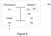
- FIG. 6 illustrates a block diagram of some components of an apparatus 200 that may be employed to implement operations described in the foregoing with references to the processing unit 150.
- the apparatus 200 comprises a processor 210 and a memory 220.
- the memory 220 may store data and computer program code 225.
- the apparatus 200 may further comprise communication means 230 for wired or wireless communication with other apparatuses.
- the communication means 230 may enable communication with apparatuses that are provided as part of the radar apparatus 100 and/or with apparatuses that are external to the radar apparatus 100. As an example of the former, the communication means 230 may enable communication with the transmitter 120 and/or with the receiver 130.
- the apparatus may further comprise user I/O (input/output) components 240 that may be arranged, together with the processor 210 and a portion of the computer program code 225, to provide the user interface for receiving input from a user and/or providing output to the user.
- the user I/O components may include user input means, such as one or more keys or buttons, a keyboard, a touchscreen or a touchpad, etc.
- the user I/O components may include output means, such as a display or a touchscreen.
- the components of the apparatus 200 are communicatively coupled to each other via a bus 250 that enables transfer of data and control information between the components.
- the memory 220 and a portion of the computer program code 225 stored therein may be further arranged, with the processor 210, to cause the apparatus 200 to perform at least some aspects of operation of the processing unit 150 described in the foregoing.
- the processor 210 is configured to read from and write to the memory 220.
- the processor 210 is depicted as a respective single component, it may be implemented as respective one or more separate processing components.
- the memory 220 is depicted as a respective single component, it may be implemented as respective one or more separate components, some or all of which may be integrated/removable and/or may provide permanent / semi-permanent/ dynamic/cached storage.
- the computer program code 225 may comprise computer-executable instructions that implement at least some aspects of operation of the processing unit 150 described in the foregoing when loaded into the processor 210.
- the computer program code 225 may include a computer program consisting of one or more sequences of one or more instructions.
- the processor 210 is able to load and execute the computer program by reading the one or more sequences of one or more instructions included therein from the memory 220.
- the one or more sequences of one or more instructions may be configured to, when executed by the processor 210, cause the apparatus 200 to perform at least some aspects of operation of the processing unit 150 described in the foregoing.
- the apparatus 200 may comprise at least one processor 210 and at least one memory 220 including the computer program code 225 for one or more programs, the at least one memory 220 and the computer program code 225 configured to, with the at least one processor 210, cause the apparatus 200 to perform at least some aspects of operation of the processing unit 150 described in the foregoing.
- the computer program code 225 may be provided e.g. a computer program product comprising at least one computer-readable non-transitory medium having the computer program code 225 stored thereon, which computer program code 225, when executed by the processor 210 causes the apparatus 200 to perform at least some aspects of operation of the processing unit 150 described in the foregoing.
- the computer-readable non-transitory medium may comprise a memory device or a record medium such as a CD-ROM, a DVD, a Blu-ray disc or another article of manufacture that tangibly embodies the computer program.
- the computer program may be provided as a signal configured to reliably transfer the computer program.
- references(s) to a processor herein should not be understood to encompass only programmable processors, but also dedicated circuits such as field-programmable gate arrays (FPGA), application specific circuits (ASIC), signal processors, etc.
- FPGA field-programmable gate arrays
- ASIC application specific circuits
- signal processors etc.
Landscapes
- Engineering & Computer Science (AREA)
- Radar, Positioning & Navigation (AREA)
- Remote Sensing (AREA)
- Physics & Mathematics (AREA)
- Computer Networks & Wireless Communication (AREA)
- General Physics & Mathematics (AREA)
- Electromagnetism (AREA)
- Aerials With Secondary Devices (AREA)
- Radar Systems Or Details Thereof (AREA)
Claims (6)
- Appareil radar (100) agencé pour fonctionner dans des études météorologiques et/ou atmosphériques pour détecter et distinguer simultanément une pluralité de cibles (40) à différentes distances de l'appareil radar (100), l'appareil (100) comprenant:un ensemble antenne (110) comprenant une antenne d'alimentation (111) agencée pour émettre des ondes radio sortantes qui représentent un signal radiofréquence transmis, RF, fourni à celle-ci et capturer un signal RF reçu qui représente des ondes radio entrantes reçues au niveau de celle-ci; etun élément de focalisation (112) comprenant un élément de lentille (112a, 112b) positionné par rapport à l'antenne d'alimentation (111) de sorte que l'antenne d'alimentation (111) est disposée plus loin d'une ouverture d'antenne de l'ensemble d'antenne (110) qu'un centre de phase (114) de l'élément de lentille (112a, 112b) et de sorte que l'antenne d'alimentation (111) est positionnée sur un plan qui est décalé du centre de phase (114) d'une distance prédéfinie (L) le long d'un axe central (A) de l'élément de lentille (112a, 112b) et qui est perpendiculaire à l'axe central (A) de l'élément de lentille (112a, 112b), ainsi agencé pour collimater les ondes radio sortantes provenant de l'antenne d'alimentation (111) dans les ondes radio concaves d'un faisceau émetteur (113) pour transmission vers une direction de surveillance et focalisation des ondes radio convexes entrantes d'un faisceau récepteur reçu au niveau de l'élément de focalisation (112) à partir de la direction de surveillance pour réception au niveau de l'antenne d'alimentation (111), dans lequel l'antenne d'alimentation (111) comprend un agencement d'antenne comprenant un premier élément d'antenne agencé pour l'émission et un second élément d'antenne agencé pour la réception, l'agencement d'antenne étant disposé sur ledit plan de sorte qu'au moins l'un des premier et second éléments d'antenne est décalé par rapport à l'axe central (A) de l'élément de lentille (112a, 112b), etdans lequel l'agencement de l'antenne d'alimentation (111) et de l'élément de focalisation (112) est configuré pour des mesures à des distances plus proches que la limite Fraunhofer définie comme
 où d désigne le diamètre de l'ouverture d'antenne de l'ensemble d'antenne (110) et où λ désigne la longueur d'onde porteuse appliquée au signal RF transmis;un émetteur (120) agencé pour fournir le signal RF transmis à l'antenne d'alimentation (111) et un récepteur (130) agencé pour recevoir le signal RF reçu et capturé au niveau de l'antenne d'alimentation (111); etune unité de traitement (150) agencée pour déterminer, sur la base du signal RF reçu en tenant compte du signal RF transmis, les caractéristiques respectives de la pluralité de cibles (40) à différentes distances de l'ensemble d'antenne (110) dans la direction de surveillance, dans lequel lesdites caractéristiques comprennent au moins l'un des éléments suivants:des emplacements respectifs de la pluralité de cibles (40),des vitesses respectives de la pluralité de cibles (40), des tailles respectives de la pluralité de cibles (40), des formes respectives de la pluralité de cibles (40).
 - Appareil radar (100) selon la revendication 1, dans lequel l'élément de focalisation (112) comprend un élément de lentille à symétrie sensiblement axiale (112a, 112b).
- Appareil radar (100) selon la revendication 1 ou 2, dans lequel la distance prédéfinie (L) est définie comme une partie prédéfinie non nulle du diamètre de la section transversale de l'élément de lentille (112a, 112b).
- Appareil radar (100) selon l'une quelconque des revendications 1 à 3, dans lequel l'élément de lentille (112a, 112b) a une section transversale sensiblement circulaire et une extrémité avant convexe qui a une forme sensiblement ellipsoïdale, où l'extrémité avant ou une partie celui-ci sert d'ouverture d'antenne de l'ensemble d'antenne (110).
- Appareil radar (100) selon l'une quelconque des revendications 1 à 4, dans lequel l'émetteur (120) et le récepteur (130) sont agencés pour appliquer l'un des éléments suivants:une émission et une réception d'une onde continue modulée en fréquence, FMCW,une émission et une réception pulsées.
- Appareil radar (100) selon la revendication 5, dans lequel l'émetteur (120) et le récepteur (130) sont configurés comme un émetteur-récepteur Doppler FMCW.
Priority Applications (4)
| Application Number | Priority Date | Filing Date | Title |
|---|---|---|---|
| EP22161061.1A EP4243209B1 (fr) | 2022-03-09 | 2022-03-09 | Appareil radar arrangé pour fonctionner dans des études météorologiques et/ou atmosphériques |
| US18/179,991 US12481023B2 (en) | 2022-03-09 | 2023-03-07 | Antenna for a radar apparatus |
| CN202310216847.2A CN116736228A (zh) | 2022-03-09 | 2023-03-08 | 用于雷达装置的天线 |
| US19/300,594 US20250370099A1 (en) | 2022-03-09 | 2025-08-14 | Antenna for a radar apparatus |
Applications Claiming Priority (1)
| Application Number | Priority Date | Filing Date | Title |
|---|---|---|---|
| EP22161061.1A EP4243209B1 (fr) | 2022-03-09 | 2022-03-09 | Appareil radar arrangé pour fonctionner dans des études météorologiques et/ou atmosphériques |
Publications (3)
| Publication Number | Publication Date |
|---|---|
| EP4243209A1 EP4243209A1 (fr) | 2023-09-13 |
| EP4243209B1 true EP4243209B1 (fr) | 2024-08-21 |
| EP4243209C0 EP4243209C0 (fr) | 2024-08-21 |
Family
ID=80685548
Family Applications (1)
| Application Number | Title | Priority Date | Filing Date |
|---|---|---|---|
| EP22161061.1A Active EP4243209B1 (fr) | 2022-03-09 | 2022-03-09 | Appareil radar arrangé pour fonctionner dans des études météorologiques et/ou atmosphériques |
Country Status (3)
| Country | Link |
|---|---|
| US (2) | US12481023B2 (fr) |
| EP (1) | EP4243209B1 (fr) |
| CN (1) | CN116736228A (fr) |
Families Citing this family (2)
| Publication number | Priority date | Publication date | Assignee | Title |
|---|---|---|---|---|
| DE102023210197A1 (de) * | 2023-10-18 | 2025-04-24 | Pepperl+Fuchs Se | Radarsensor |
| CN118315823A (zh) * | 2024-04-29 | 2024-07-09 | 电子科技大学 | 一种空气柱填充的近场天线波束校正结构 |
Citations (2)
| Publication number | Priority date | Publication date | Assignee | Title |
|---|---|---|---|---|
| US2716746A (en) * | 1950-10-31 | 1955-08-30 | Rca Corp | Focusing of radar beams for a tracking radar |
| JP2010002350A (ja) * | 2008-06-20 | 2010-01-07 | Fujitsu Ten Ltd | レーダ装置 |
Family Cites Families (38)
| Publication number | Priority date | Publication date | Assignee | Title |
|---|---|---|---|---|
| US3775769A (en) * | 1971-10-04 | 1973-11-27 | Raytheon Co | Phased array system |
| NL8301568A (nl) * | 1983-05-04 | 1984-12-03 | Hollandse Signaalapparaten Bv | Impulsradarapparaat. |
| JP2768439B2 (ja) * | 1994-11-08 | 1998-06-25 | 本田技研工業株式会社 | Fm−cw方式マルチビームレーダー装置 |
| JP3433417B2 (ja) * | 1998-04-02 | 2003-08-04 | トヨタ自動車株式会社 | レーダ装置 |
| NL1010062C2 (nl) * | 1998-09-10 | 2000-03-13 | Hollandse Signaalapparaten Bv | Radarapparaat. |
| US6441793B1 (en) * | 2000-03-16 | 2002-08-27 | Austin Information Systems, Inc. | Method and apparatus for wireless communications and sensing utilizing a non-collimating lens |
| JP4447946B2 (ja) * | 2004-03-22 | 2010-04-07 | 富士通テン株式会社 | レーダ装置 |
| US8478344B2 (en) * | 2006-06-21 | 2013-07-02 | Broadcom Corporation | Power recovery circuit based on partial standing waves |
| US7663546B1 (en) * | 2006-06-23 | 2010-02-16 | Oceanit Laboratories, Inc. | Real-time autonomous beam steering array for satellite communications |
| JP5091651B2 (ja) * | 2007-12-14 | 2012-12-05 | 日立オートモティブシステムズ株式会社 | レーダ装置及びターゲットの方位角計測方法 |
| EP2128576B1 (fr) * | 2008-05-27 | 2016-12-28 | VEGA Grieshaber KG | Procédé de détection de double parole basé sur les propriétés acoustiques spectrales |
| US8588805B2 (en) * | 2008-12-13 | 2013-11-19 | Broadcom Corporation | Receiver utilizing multiple radiation patterns to determine angular position |
| US8487810B2 (en) * | 2009-09-16 | 2013-07-16 | Broadcom Corporation | Integrated and configurable radar system |
| WO2011080688A2 (fr) * | 2009-12-28 | 2011-07-07 | Cover Technology S.R.L. | Appareil de radar, et vêtement et ensemble de vêtement comprenant un tel appareil |
| EP2853915B1 (fr) * | 2012-05-21 | 2018-12-26 | Toyota Jidosha Kabushiki Kaisha | Dispositif de radar et procédé de vérification d'angle |
| JP5912879B2 (ja) * | 2012-05-31 | 2016-04-27 | 株式会社デンソー | レーダ装置 |
| US9857463B2 (en) * | 2012-11-12 | 2018-01-02 | Sony Corporation | Radar apparatus and method |
| EP2824477A1 (fr) * | 2013-07-10 | 2015-01-14 | BAE Systems PLC | Annulation d'interférence du type multitrajets dans un radar d'impulsion avec des faisceaux étagés |
| US9246227B2 (en) * | 2013-07-28 | 2016-01-26 | Finetek Co., Ltd. | Horn antenna device and step-shaped signal feed-in apparatus thereof |
| US9373896B2 (en) * | 2013-09-05 | 2016-06-21 | Viasat, Inc | True time delay compensation in wideband phased array fed reflector antenna systems |
| US9229100B2 (en) * | 2013-09-20 | 2016-01-05 | Toyota Motor Engineering & Manufacturing North America, Inc. | Phased array radar with monopulse algorithm measurement |
| US9793963B2 (en) * | 2013-11-27 | 2017-10-17 | Avago Technologies General Ip (Singapore) Pte. | Integrated circuit with antenna arrays and methods for use therewith |
| JP6446331B2 (ja) * | 2015-06-08 | 2018-12-26 | 日立オートモティブシステムズ株式会社 | 扁平ビーム生成アンテナを有するセンサ |
| US10908279B2 (en) * | 2016-03-11 | 2021-02-02 | Facebook Technologies, Llc | Ultrasound/radar for eye tracking |
| WO2017193269A1 (fr) * | 2016-05-10 | 2017-11-16 | 深圳市速腾聚创科技有限公司 | Lidar multiligne |
| US11750303B2 (en) * | 2016-06-30 | 2023-09-05 | Keysight Technologies, Inc. | Compact system for characterizing a device under test (DUT) having integrated antenna array |
| CN110809704B (zh) * | 2017-05-08 | 2022-11-01 | 威力登激光雷达美国有限公司 | Lidar数据获取与控制 |
| JP6887091B2 (ja) * | 2017-10-10 | 2021-06-16 | パナソニックIpマネジメント株式会社 | レーダ装置 |
| US10962637B2 (en) * | 2018-06-25 | 2021-03-30 | Texas Instruments Incorporated | Radar data processing using neural network classifier and confidence metrics |
| CN109116367B (zh) * | 2018-06-27 | 2020-05-19 | 上海禾赛光电科技有限公司 | 一种激光雷达 |
| WO2020206602A1 (fr) * | 2019-04-09 | 2020-10-15 | 华为技术有限公司 | Procédé, appareil et dispositif de mesure de distance |
| US11539144B2 (en) * | 2019-06-03 | 2022-12-27 | Raymond Albert Fillion | Phased array antenna with isotropic and non-isotropic radiating and omnidirectional and non-omnidirectional receiving elements |
| DE112020002389T5 (de) * | 2019-06-10 | 2022-01-27 | Murata Manufacturing Co., Ltd. | Radarvorrichtung, fahrzeug und verfahren zum entfernen eines unnötigen punkts |
| US11764615B2 (en) * | 2019-07-11 | 2023-09-19 | Google Llc | Radiative wireless charging system |
| US11431103B2 (en) * | 2020-07-17 | 2022-08-30 | Huawei Technologies Co., Ltd. | Systems and methods for beamforming using integrated configurable surfaces in antenna |
| EP3971611A1 (fr) * | 2020-09-17 | 2022-03-23 | VEGA Grieshaber KG | Appareil de mesure radar |
| EP4130793A1 (fr) * | 2021-08-06 | 2023-02-08 | Aptiv Technologies Limited | Système radar |
| WO2023027104A1 (fr) * | 2021-08-25 | 2023-03-02 | 国立大学法人電気通信大学 | Dispositif de commande de front d'onde et dispositif optique adaptatif |
-
2022
- 2022-03-09 EP EP22161061.1A patent/EP4243209B1/fr active Active
-
2023
- 2023-03-07 US US18/179,991 patent/US12481023B2/en active Active
- 2023-03-08 CN CN202310216847.2A patent/CN116736228A/zh active Pending
-
2025
- 2025-08-14 US US19/300,594 patent/US20250370099A1/en active Pending
Patent Citations (2)
| Publication number | Priority date | Publication date | Assignee | Title |
|---|---|---|---|---|
| US2716746A (en) * | 1950-10-31 | 1955-08-30 | Rca Corp | Focusing of radar beams for a tracking radar |
| JP2010002350A (ja) * | 2008-06-20 | 2010-01-07 | Fujitsu Ten Ltd | レーダ装置 |
Non-Patent Citations (3)
| Title |
|---|
| "Radar Handbook", 1 January 1990, MCGRAW-HILL, New York [u.a.], ISBN: 978-0-07-057913-2, article SAUNDERS WILLIAM K.: "CW and FM Radar", pages: 14.1 - 14.45, XP093060665, 024245 * |
| KILDAL P-S ET AL: "Characterisation of near-field focusing with application to low altitude beam focusing of the Arecibo tri-reflector system", IEE PROCEEDINGS: MICROWAVES, ANTENNAS AND PROPAGATION, IEE, STEVENAGE, HERTS, GB, vol. 143, no. 4, 13 August 1996 (1996-08-13), pages 284 - 292, XP006006571, ISSN: 1350-2417, DOI: 10.1049/IP-MAP:19960388 * |
| OLVER A D ET AL: "VARIABLE BEAMWIDTH REFLECTOR ANTENNA BY FEED DEFOCUSING", IEE PROCEEDINGS: MICROWAVES, ANTENNAS AND PROPAGATION, IEE, STEVENAGE, HERTS, GB, vol. 142, no. 5, 1 October 1995 (1995-10-01), pages 394 - 398, XP000535601, ISSN: 1350-2417, DOI: 10.1049/IP-MAP:19952082 * |
Also Published As
| Publication number | Publication date |
|---|---|
| US20230288535A1 (en) | 2023-09-14 |
| US20250370099A1 (en) | 2025-12-04 |
| EP4243209C0 (fr) | 2024-08-21 |
| US12481023B2 (en) | 2025-11-25 |
| CN116736228A (zh) | 2023-09-12 |
| EP4243209A1 (fr) | 2023-09-13 |
Similar Documents
| Publication | Publication Date | Title |
|---|---|---|
| JP3634378B2 (ja) | レーダシステム、例えば、自動車レーダシステム | |
| US20250370099A1 (en) | Antenna for a radar apparatus | |
| US12386063B2 (en) | Autonomous moving object | |
| US4855747A (en) | Method of target imaging and identification | |
| Li et al. | Radar and inverse scattering | |
| US20130016001A1 (en) | Radar sensor | |
| CN113687313B (zh) | 一种基于双反射面天线的星载x+s双频sar系统 | |
| CN110109072A (zh) | 一种多基地海上小目标雷达探测方法 | |
| US10802112B2 (en) | Method, device, and system for simultaneously detecting different weapon threats using reflected radar return signals | |
| US20180074180A1 (en) | Ultrafast target detection based on microwave metamaterials | |
| US11067686B2 (en) | Obstacle position and extent measurement by automotive radar | |
| AU2021202812B2 (en) | System for recognizing and/or determining the volume of bodies or substances made of dielectric and/or conductive material | |
| US20230288532A1 (en) | Antenna for a radar apparatus | |
| CN114924269A (zh) | 一种基于星载f-scan sar的距离向模糊度分析方法 | |
| Chan et al. | A beam scanning frequency modulated continuous wave radar | |
| Zhao et al. | A novel method of ship detection by combining space-borne SAR and GNSS-R | |
| Artyushenko et al. | Measurement error estimation of motion variables for extended objects under changing range conditions | |
| JP2005083814A (ja) | レーダ装置 | |
| RU2287840C1 (ru) | Способ обнаружения и классификации надводных целей | |
| Kuznietsov et al. | Analysis of possibilities of providing of necessary exactness of measuring of spatial coordinates of air objects in the radio-location station of accompaniment with phase aerial by a grate | |
| Richards et al. | Wide-Angle Direction Finder using a Modified Partial Maxwell Fisheye Lens | |
| JP7596180B2 (ja) | レーダ装置、飛しょう体および誘導プログラム | |
| CN114646975B (zh) | 局部多发多收天线阵列、实时成像系统和实时安检装置 | |
| Wang et al. | Weak target detection algorithm for non-cooperative bistatic radar | |
| Muppala et al. | Single Transceiver 3-D Radar Imaging at 80 GHz Via Affine Phase Center Translations |
Legal Events
| Date | Code | Title | Description |
|---|---|---|---|
| STAA | Information on the status of an ep patent application or granted ep patent |
Free format text: STATUS: EXAMINATION IS IN PROGRESS |
|
| PUAI | Public reference made under article 153(3) epc to a published international application that has entered the european phase |
Free format text: ORIGINAL CODE: 0009012 |
|
| 17P | Request for examination filed |
Effective date: 20221202 |
|
| AK | Designated contracting states |
Kind code of ref document: A1 Designated state(s): AL AT BE BG CH CY CZ DE DK EE ES FI FR GB GR HR HU IE IS IT LI LT LU LV MC MK MT NL NO PL PT RO RS SE SI SK SM TR |
|
| GRAP | Despatch of communication of intention to grant a patent |
Free format text: ORIGINAL CODE: EPIDOSNIGR1 |
|
| STAA | Information on the status of an ep patent application or granted ep patent |
Free format text: STATUS: GRANT OF PATENT IS INTENDED |
|
| RIC1 | Information provided on ipc code assigned before grant |
Ipc: H01Q 19/12 20060101ALN20240119BHEP Ipc: H01Q 15/16 20060101ALN20240119BHEP Ipc: H01Q 15/02 20060101ALN20240119BHEP Ipc: H01Q 25/00 20060101ALI20240119BHEP Ipc: H01Q 19/06 20060101AFI20240119BHEP |
|
| INTG | Intention to grant announced |
Effective date: 20240207 |
|
| GRAJ | Information related to disapproval of communication of intention to grant by the applicant or resumption of examination proceedings by the epo deleted |
Free format text: ORIGINAL CODE: EPIDOSDIGR1 |
|
| STAA | Information on the status of an ep patent application or granted ep patent |
Free format text: STATUS: EXAMINATION IS IN PROGRESS |
|
| GRAP | Despatch of communication of intention to grant a patent |
Free format text: ORIGINAL CODE: EPIDOSNIGR1 |
|
| STAA | Information on the status of an ep patent application or granted ep patent |
Free format text: STATUS: GRANT OF PATENT IS INTENDED |
|
| INTC | Intention to grant announced (deleted) | ||
| RIC1 | Information provided on ipc code assigned before grant |
Ipc: H01Q 19/12 20060101ALN20240313BHEP Ipc: H01Q 15/16 20060101ALN20240313BHEP Ipc: H01Q 15/02 20060101ALN20240313BHEP Ipc: H01Q 25/00 20060101ALI20240313BHEP Ipc: H01Q 19/06 20060101AFI20240313BHEP |
|
| INTG | Intention to grant announced |
Effective date: 20240325 |
|
| GRAS | Grant fee paid |
Free format text: ORIGINAL CODE: EPIDOSNIGR3 |
|
| GRAA | (expected) grant |
Free format text: ORIGINAL CODE: 0009210 |
|
| STAA | Information on the status of an ep patent application or granted ep patent |
Free format text: STATUS: THE PATENT HAS BEEN GRANTED |
|
| AK | Designated contracting states |
Kind code of ref document: B1 Designated state(s): AL AT BE BG CH CY CZ DE DK EE ES FI FR GB GR HR HU IE IS IT LI LT LU LV MC MK MT NL NO PL PT RO RS SE SI SK SM TR |
|
| REG | Reference to a national code |
Ref country code: GB Ref legal event code: FG4D |
|
| REG | Reference to a national code |
Ref country code: CH Ref legal event code: EP |
|
| REG | Reference to a national code |
Ref country code: DE Ref legal event code: R096 Ref document number: 602022005400 Country of ref document: DE |
|
| REG | Reference to a national code |
Ref country code: IE Ref legal event code: FG4D |
|
| U01 | Request for unitary effect filed |
Effective date: 20240920 |
|
| U07 | Unitary effect registered |
Designated state(s): AT BE BG DE DK EE FI FR IT LT LU LV MT NL PT RO SE SI Effective date: 20241015 |
|
| PG25 | Lapsed in a contracting state [announced via postgrant information from national office to epo] |
Ref country code: NO Free format text: LAPSE BECAUSE OF FAILURE TO SUBMIT A TRANSLATION OF THE DESCRIPTION OR TO PAY THE FEE WITHIN THE PRESCRIBED TIME-LIMIT Effective date: 20241121 |
|
| PG25 | Lapsed in a contracting state [announced via postgrant information from national office to epo] |
Ref country code: PL Free format text: LAPSE BECAUSE OF FAILURE TO SUBMIT A TRANSLATION OF THE DESCRIPTION OR TO PAY THE FEE WITHIN THE PRESCRIBED TIME-LIMIT Effective date: 20240821 Ref country code: GR Free format text: LAPSE BECAUSE OF FAILURE TO SUBMIT A TRANSLATION OF THE DESCRIPTION OR TO PAY THE FEE WITHIN THE PRESCRIBED TIME-LIMIT Effective date: 20241122 |
|
| PG25 | Lapsed in a contracting state [announced via postgrant information from national office to epo] |
Ref country code: IS Free format text: LAPSE BECAUSE OF FAILURE TO SUBMIT A TRANSLATION OF THE DESCRIPTION OR TO PAY THE FEE WITHIN THE PRESCRIBED TIME-LIMIT Effective date: 20241221 |
|
| PG25 | Lapsed in a contracting state [announced via postgrant information from national office to epo] |
Ref country code: HR Free format text: LAPSE BECAUSE OF FAILURE TO SUBMIT A TRANSLATION OF THE DESCRIPTION OR TO PAY THE FEE WITHIN THE PRESCRIBED TIME-LIMIT Effective date: 20240821 |
|
| PG25 | Lapsed in a contracting state [announced via postgrant information from national office to epo] |
Ref country code: ES Free format text: LAPSE BECAUSE OF FAILURE TO SUBMIT A TRANSLATION OF THE DESCRIPTION OR TO PAY THE FEE WITHIN THE PRESCRIBED TIME-LIMIT Effective date: 20240821 Ref country code: RS Free format text: LAPSE BECAUSE OF FAILURE TO SUBMIT A TRANSLATION OF THE DESCRIPTION OR TO PAY THE FEE WITHIN THE PRESCRIBED TIME-LIMIT Effective date: 20241121 |
|
| PG25 | Lapsed in a contracting state [announced via postgrant information from national office to epo] |
Ref country code: RS Free format text: LAPSE BECAUSE OF FAILURE TO SUBMIT A TRANSLATION OF THE DESCRIPTION OR TO PAY THE FEE WITHIN THE PRESCRIBED TIME-LIMIT Effective date: 20241121 Ref country code: PL Free format text: LAPSE BECAUSE OF FAILURE TO SUBMIT A TRANSLATION OF THE DESCRIPTION OR TO PAY THE FEE WITHIN THE PRESCRIBED TIME-LIMIT Effective date: 20240821 Ref country code: NO Free format text: LAPSE BECAUSE OF FAILURE TO SUBMIT A TRANSLATION OF THE DESCRIPTION OR TO PAY THE FEE WITHIN THE PRESCRIBED TIME-LIMIT Effective date: 20241121 Ref country code: IS Free format text: LAPSE BECAUSE OF FAILURE TO SUBMIT A TRANSLATION OF THE DESCRIPTION OR TO PAY THE FEE WITHIN THE PRESCRIBED TIME-LIMIT Effective date: 20241221 Ref country code: HR Free format text: LAPSE BECAUSE OF FAILURE TO SUBMIT A TRANSLATION OF THE DESCRIPTION OR TO PAY THE FEE WITHIN THE PRESCRIBED TIME-LIMIT Effective date: 20240821 Ref country code: GR Free format text: LAPSE BECAUSE OF FAILURE TO SUBMIT A TRANSLATION OF THE DESCRIPTION OR TO PAY THE FEE WITHIN THE PRESCRIBED TIME-LIMIT Effective date: 20241122 Ref country code: ES Free format text: LAPSE BECAUSE OF FAILURE TO SUBMIT A TRANSLATION OF THE DESCRIPTION OR TO PAY THE FEE WITHIN THE PRESCRIBED TIME-LIMIT Effective date: 20240821 |
|
| PG25 | Lapsed in a contracting state [announced via postgrant information from national office to epo] |
Ref country code: SM Free format text: LAPSE BECAUSE OF FAILURE TO SUBMIT A TRANSLATION OF THE DESCRIPTION OR TO PAY THE FEE WITHIN THE PRESCRIBED TIME-LIMIT Effective date: 20240821 |
|
| PG25 | Lapsed in a contracting state [announced via postgrant information from national office to epo] |
Ref country code: CZ Free format text: LAPSE BECAUSE OF FAILURE TO SUBMIT A TRANSLATION OF THE DESCRIPTION OR TO PAY THE FEE WITHIN THE PRESCRIBED TIME-LIMIT Effective date: 20240821 |
|
| PG25 | Lapsed in a contracting state [announced via postgrant information from national office to epo] |
Ref country code: SK Free format text: LAPSE BECAUSE OF FAILURE TO SUBMIT A TRANSLATION OF THE DESCRIPTION OR TO PAY THE FEE WITHIN THE PRESCRIBED TIME-LIMIT Effective date: 20240821 |
|
| U21 | Renewal fee for the european patent with unitary effect paid with additional fee |
Year of fee payment: 4 Effective date: 20250520 |
|
| PLBE | No opposition filed within time limit |
Free format text: ORIGINAL CODE: 0009261 |
|
| STAA | Information on the status of an ep patent application or granted ep patent |
Free format text: STATUS: NO OPPOSITION FILED WITHIN TIME LIMIT |
|
| 26N | No opposition filed |
Effective date: 20250522 |
|
| PG25 | Lapsed in a contracting state [announced via postgrant information from national office to epo] |
Ref country code: MC Free format text: LAPSE BECAUSE OF FAILURE TO SUBMIT A TRANSLATION OF THE DESCRIPTION OR TO PAY THE FEE WITHIN THE PRESCRIBED TIME-LIMIT Effective date: 20240821 |
|
| REG | Reference to a national code |
Ref country code: CH Ref legal event code: H13 Free format text: ST27 STATUS EVENT CODE: U-0-0-H10-H13 (AS PROVIDED BY THE NATIONAL OFFICE) Effective date: 20251023 |
|
| PG25 | Lapsed in a contracting state [announced via postgrant information from national office to epo] |
Ref country code: CH Free format text: LAPSE BECAUSE OF NON-PAYMENT OF DUE FEES Effective date: 20250331 |
|
| PG25 | Lapsed in a contracting state [announced via postgrant information from national office to epo] |
Ref country code: IE Free format text: LAPSE BECAUSE OF NON-PAYMENT OF DUE FEES Effective date: 20250309 |
|
| PGFP | Annual fee paid to national office [announced via postgrant information from national office to epo] |
Ref country code: GB Payment date: 20260324 Year of fee payment: 5 |
|
| U20 | Renewal fee for the european patent with unitary effect paid |
Year of fee payment: 5 Effective date: 20260309 |