EP4243702B1 - Dispositif chirurgical et système - Google Patents
Dispositif chirurgical et système Download PDFInfo
- Publication number
- EP4243702B1 EP4243702B1 EP20806997.1A EP20806997A EP4243702B1 EP 4243702 B1 EP4243702 B1 EP 4243702B1 EP 20806997 A EP20806997 A EP 20806997A EP 4243702 B1 EP4243702 B1 EP 4243702B1
- Authority
- EP
- European Patent Office
- Prior art keywords
- needle
- surgical device
- felting
- penetration depth
- felting needle
- Prior art date
- Legal status (The legal status is an assumption and is not a legal conclusion. Google has not performed a legal analysis and makes no representation as to the accuracy of the status listed.)
- Active
Links
Images


Classifications
-
- A—HUMAN NECESSITIES
- A61—MEDICAL OR VETERINARY SCIENCE; HYGIENE
- A61B—DIAGNOSIS; SURGERY; IDENTIFICATION
- A61B17/00—Surgical instruments, devices or methods
- A61B17/34—Trocars; Puncturing needles
- A61B17/3468—Trocars; Puncturing needles for implanting or removing devices, e.g. prostheses, implants, seeds, wires
-
- A—HUMAN NECESSITIES
- A61—MEDICAL OR VETERINARY SCIENCE; HYGIENE
- A61B—DIAGNOSIS; SURGERY; IDENTIFICATION
- A61B17/00—Surgical instruments, devices or methods
- A61B17/04—Surgical instruments, devices or methods for suturing wounds; Holders or packages for needles or suture materials
- A61B17/06—Needles ; Sutures; Needle-suture combinations; Holders or packages for needles or suture materials
- A61B17/06066—Needles, e.g. needle tip configurations
-
- A—HUMAN NECESSITIES
- A61—MEDICAL OR VETERINARY SCIENCE; HYGIENE
- A61B—DIAGNOSIS; SURGERY; IDENTIFICATION
- A61B17/00—Surgical instruments, devices or methods
- A61B17/04—Surgical instruments, devices or methods for suturing wounds; Holders or packages for needles or suture materials
- A61B17/0469—Suturing instruments for use in minimally invasive surgery, e.g. endoscopic surgery
-
- A—HUMAN NECESSITIES
- A61—MEDICAL OR VETERINARY SCIENCE; HYGIENE
- A61B—DIAGNOSIS; SURGERY; IDENTIFICATION
- A61B17/00—Surgical instruments, devices or methods
- A61B17/04—Surgical instruments, devices or methods for suturing wounds; Holders or packages for needles or suture materials
- A61B17/0482—Needle or suture guides
-
- A—HUMAN NECESSITIES
- A61—MEDICAL OR VETERINARY SCIENCE; HYGIENE
- A61B—DIAGNOSIS; SURGERY; IDENTIFICATION
- A61B17/00—Surgical instruments, devices or methods
- A61B17/04—Surgical instruments, devices or methods for suturing wounds; Holders or packages for needles or suture materials
- A61B17/0491—Sewing machines for surgery
-
- A—HUMAN NECESSITIES
- A61—MEDICAL OR VETERINARY SCIENCE; HYGIENE
- A61B—DIAGNOSIS; SURGERY; IDENTIFICATION
- A61B17/00—Surgical instruments, devices or methods
- A61B17/04—Surgical instruments, devices or methods for suturing wounds; Holders or packages for needles or suture materials
- A61B17/06—Needles ; Sutures; Needle-suture combinations; Holders or packages for needles or suture materials
- A61B17/062—Needle manipulators
-
- A—HUMAN NECESSITIES
- A61—MEDICAL OR VETERINARY SCIENCE; HYGIENE
- A61B—DIAGNOSIS; SURGERY; IDENTIFICATION
- A61B90/00—Instruments, implements or accessories specially adapted for surgery or diagnosis and not covered by any of the groups A61B1/00 - A61B50/00, e.g. for luxation treatment or for protecting wound edges
- A61B90/03—Automatic limiting or abutting means, e.g. for safety
-
- A—HUMAN NECESSITIES
- A61—MEDICAL OR VETERINARY SCIENCE; HYGIENE
- A61B—DIAGNOSIS; SURGERY; IDENTIFICATION
- A61B17/00—Surgical instruments, devices or methods
- A61B2017/00017—Electrical control of surgical instruments
- A61B2017/00022—Sensing or detecting at the treatment site
-
- A—HUMAN NECESSITIES
- A61—MEDICAL OR VETERINARY SCIENCE; HYGIENE
- A61B—DIAGNOSIS; SURGERY; IDENTIFICATION
- A61B17/00—Surgical instruments, devices or methods
- A61B2017/00367—Details of actuation of instruments, e.g. relations between pushing buttons, or the like, and activation of the tool, working tip, or the like
- A61B2017/00398—Details of actuation of instruments, e.g. relations between pushing buttons, or the like, and activation of the tool, working tip, or the like using powered actuators, e.g. stepper motors, solenoids
-
- A—HUMAN NECESSITIES
- A61—MEDICAL OR VETERINARY SCIENCE; HYGIENE
- A61B—DIAGNOSIS; SURGERY; IDENTIFICATION
- A61B17/00—Surgical instruments, devices or methods
- A61B2017/00535—Surgical instruments, devices or methods pneumatically or hydraulically operated
-
- A—HUMAN NECESSITIES
- A61—MEDICAL OR VETERINARY SCIENCE; HYGIENE
- A61B—DIAGNOSIS; SURGERY; IDENTIFICATION
- A61B90/00—Instruments, implements or accessories specially adapted for surgery or diagnosis and not covered by any of the groups A61B1/00 - A61B50/00, e.g. for luxation treatment or for protecting wound edges
- A61B90/03—Automatic limiting or abutting means, e.g. for safety
- A61B2090/032—Automatic limiting or abutting means, e.g. for safety pressure limiting, e.g. hydrostatic
-
- A—HUMAN NECESSITIES
- A61—MEDICAL OR VETERINARY SCIENCE; HYGIENE
- A61B—DIAGNOSIS; SURGERY; IDENTIFICATION
- A61B90/00—Instruments, implements or accessories specially adapted for surgery or diagnosis and not covered by any of the groups A61B1/00 - A61B50/00, e.g. for luxation treatment or for protecting wound edges
- A61B90/03—Automatic limiting or abutting means, e.g. for safety
- A61B2090/033—Abutting means, stops, e.g. abutting on tissue or skin
-
- A—HUMAN NECESSITIES
- A61—MEDICAL OR VETERINARY SCIENCE; HYGIENE
- A61B—DIAGNOSIS; SURGERY; IDENTIFICATION
- A61B90/00—Instruments, implements or accessories specially adapted for surgery or diagnosis and not covered by any of the groups A61B1/00 - A61B50/00, e.g. for luxation treatment or for protecting wound edges
- A61B90/03—Automatic limiting or abutting means, e.g. for safety
- A61B2090/033—Abutting means, stops, e.g. abutting on tissue or skin
- A61B2090/034—Abutting means, stops, e.g. abutting on tissue or skin abutting on parts of the device itself
-
- A—HUMAN NECESSITIES
- A61—MEDICAL OR VETERINARY SCIENCE; HYGIENE
- A61B—DIAGNOSIS; SURGERY; IDENTIFICATION
- A61B90/00—Instruments, implements or accessories specially adapted for surgery or diagnosis and not covered by any of the groups A61B1/00 - A61B50/00, e.g. for luxation treatment or for protecting wound edges
- A61B90/03—Automatic limiting or abutting means, e.g. for safety
- A61B2090/033—Abutting means, stops, e.g. abutting on tissue or skin
- A61B2090/036—Abutting means, stops, e.g. abutting on tissue or skin abutting on tissue or skin
-
- A—HUMAN NECESSITIES
- A61—MEDICAL OR VETERINARY SCIENCE; HYGIENE
- A61B—DIAGNOSIS; SURGERY; IDENTIFICATION
- A61B90/00—Instruments, implements or accessories specially adapted for surgery or diagnosis and not covered by any of the groups A61B1/00 - A61B50/00, e.g. for luxation treatment or for protecting wound edges
- A61B90/03—Automatic limiting or abutting means, e.g. for safety
- A61B2090/037—Automatic limiting or abutting means, e.g. for safety with a frangible part, e.g. by reduced diameter
-
- A—HUMAN NECESSITIES
- A61—MEDICAL OR VETERINARY SCIENCE; HYGIENE
- A61B—DIAGNOSIS; SURGERY; IDENTIFICATION
- A61B90/00—Instruments, implements or accessories specially adapted for surgery or diagnosis and not covered by any of the groups A61B1/00 - A61B50/00, e.g. for luxation treatment or for protecting wound edges
- A61B90/06—Measuring instruments not otherwise provided for
- A61B2090/062—Measuring instruments not otherwise provided for penetration depth
Definitions
- the present invention relates to a surgical device, a system, and a method of manufacturing a surgical device according to the preambles of the independent claims.
- the present applicant recently developed a surgical felting device allowing a biomechanically advantageous implantation of implants.
- the developed device allows an improved fixation as compared to conventional suturing techniques.
- One example of such a surgical felting device is disclosed in PCT/CH2019/000015 .
- the surgical felting device comprises a needle that repeatedly moves through a surgical felt and into tissue. By embedding strands of the felt inside the tissue, the needle creates a strong and well distributed mechanical bond between the felt and the tissue.
- this technique is faster and alleviates adverse effects such as "cheesewiring" of suture, where the suture cuts through tissue which can happen through local stress peaks.
- the surgical felting device may be handheld and the needle moves at high speeds, there is high risk of needle damage.
- the damage may result from collisions between the needle and rigid structures such as bones or other surgical tools. Such collisions could lead to a partial destruction of the needle (plastic bending, breaking or splintering) which adversely influences the functionality. Even further, parts of the needle may be lost inside the patient's body, presenting a health risk.
- the high speeds of the needles in the tissue and in the surgical felt may generate undesirable heat that results from friction.
- US 2015/231368 A1 discloses a needle-injection catheter that includes a catheter body having a distal end, a proximal end, a stiff proximal portion, a flexible distal portion, and a delivery lumen extending therethrough.
- a straight injection needle extends coaxially from a distal tip of the flexible portion of the catheter body, and a plurality of penetration limiting elements positioned circumferentially about a base of the straight injection needle and configured to fold radially inwardly against a shaft of the needle when constrained in a tubular lumen and to extend radially outwardly when unconstrained.
- a helical needle extends from the distal tip of the flexible portion of the catheter body.
- the helical needle has at least one helical delivery lumen connected to receive an injectable substance from the delivery lumen of the catheter body.
- EP 3 066 999 A1 discloses a catheter system that includes a positioning catheter for receiving an injection needle into its lumen.
- the injection needle incorporates a plurality of loops that are mounted directly onto its shaft.
- the loops are individually biased to transition from a folded configuration, and into a deployed configuration.
- the loops create a barrier that is oriented perpendicular to the needle.
- the barrier acts to limit the depth of insertion of the needle into target tissue of a patient, to a predetermined depth, and to prevent perforation of the target tissue by the catheter tip.
- US 8,454,494 B2 discloses a support apparatus connects with and provides fluid communication between a needle and a syringe.
- the support apparatus includes at least one arm that is configured to provide cantilever support of the needle and syringe while the needle is inserted in a patient.
- the arm engages the patient's skin, and may be rigid, malleable, hinged, stretchable, telescoping, and/or have other properties.
- the support apparatus may form part of an adapter that also includes a pressure sensor. The pressure sensor senses the pressure of fluid in a gastric band system when the needle is inserted in an injection port of the gastric band system.
- a cable may extend from the pressure sensor to a display device, and may include markings configured to provide measurement from the needle to a patient's xyphoid process. Such a measurement may be factored into a calculation to account for hydrostatic pressure differences in pressure readings.
- US 2010/145306 A1 discloses a catheter device comprising a proboscis shaft and a proboscis disposed within the proboscis shaft.
- the catheter device further comprises an elongate tubular member, wherein the proboscis shaft is disposed within the elongate tubular member.
- the catheter device comprises a tissue surface engagement structure, which has a first configuration and a second configuration. In the second configuration, the tissue surface engagement structure presents a larger transverse profile in comparison to the first configuration.
- the tissue surface engagement structure may have any of various designs, including an expandable assembly and a hinged assembly.
- a deformable cushion is positioned at the distal end of the proboscis shaft. The deformable cushion comprises a pocket that is filled with a reshapeable material.
- the proboscis shaft comprises a longitudinally compressible portion.
- a further object of the present invention may be to reduce the heat generated by the felting needle.
- One aspect of the invention relates to a surgical device for felting an implant to soft tissue of a patient.
- the patient may be a human or an animal.
- Felting may be understood as the process of moving a felting needle repeatedly into, and in some embodiments through, an implant comprising a felt and thereby entangling fibers of a felt.
- a felting needle may be understood as a needle including barbs that catch the fibers of the felt and move the fibers through the felt and which entangles the fibers of the felt further.
- the felting may not only entangle the fibers of a felt that forms part of an implant with each other but also entangle the fibers of the tissue of a patient with the fibers of the felt. Thereby, some strands of the felt become embedded in and entangled with the patient's tissue and some strands of the tissue fibers may become embedded in and entangled with the felt. This creates a strong and well distributed mechanical bond between tissue and felt.
- the present invention relates to a surgical device for felting an implant to soft tissue of a patient as defined by independent claim 1. Preferred embodiments are given in the dependent claims.
- the surgical device comprises at least one felting needle.
- the at least one felting needle is configured to move reciprocally.
- a reciprocating motion as mentioned herein may be understood to be a repetitive back and forth motion.
- the motion may be translational, i.e. linear, or rotational.
- the surgical device comprises a connection interface for connecting the at least one felting needle to an actuator and for transferring a reciprocal motion from the interface to the at least one felting needle.
- the interface may provide a releasable or a permanent attachment.
- the releasable interface may include pins, latches, screws, magnets or other known mechanical or other connection means.
- a permanent attachment using rivets, glue or a one-piece design is also possible.
- a releasable attachment of the at least one needle would allow the at least one needle to be replaced.
- the device includes a water cooling system to cool down friction heat which is generated by the oscillating needle.
- the actuator may be pneumatic, hydraulic or electromagnetic.
- the actuator may be an electric motor or may comprise or use electromagnetic coils or pneumatic or hydraulic pressure.
- the device may be configured to convert a rotational motion of the actuator to a translational motion.
- the device may comprise a scotch yoke mechanism or a piston rod drive mechanism to transform a rotational motion into a translational motion. Thereby, more efficient motors may be used.
- a speed and/or frequency of the reciprocal translational motion (oscillation) can be adjustable.
- the device may comprise a linear motion rod to transfer the reciprocal motion from the interface or the actuator to the at least one needle.
- bearings and low friction materials e.g. polytetrafluorethylene
- the at least one needle is preferably made of or comprises stainless steel.
- the needle may include a stainless steel coating.
- Stainless steel is particularly resistant to the oxidizing conditions of the surgical operation.
- the present device may e.g. be used in arthroscopic surgeries, in which a constant saline flush is applied, that may oxidize the needle.
- the device comprises a needle protection mechanism.
- the needle protection mechanism prevents the at least one needle from being damaged during the reciprocal motion due to a contact with a rigid structure.
- the needle protection mechanism may define a maximal penetration depth of the at least one needle.
- the maximal penetration depth may be adjustable.
- the maximum penetration depth may be less than the amplitude of the reciprocal motion.
- the needle protection mechanism may limit the reciprocal motion or may be configured to detect an obstacle (i.e. hard tissue) or may decouple an actuator from the at least one needle in case a collision occurs or any combination thereof.
- the motion may be limited by modifying the amplitude of the reciprocal motion and/or by limiting the maximal penetration depth.
- the rigid structure may be for example the bone of a patient or another surgical tool that may come in contact the needle while the needle is actuated.
- the surgical device may be used for the repair or fixation of anatomical structures such as: collagenous tissues such as tendons, menisici, spinal disks or fascia, ligament reconstructions (collateral ligaments, cruciate ligaments, etc.), subcutaneous sutures, conventional suturing of skin closures, skeletal muscle, heart muscle, valves, and hollow organs (large vessels, bladder, esophagus, possibly intestine).
- an implant may be attached to these anatomical structures.
- the at least one felting needle has a width or diameter of less than 0.8 mm, preferably less than 0.6 mm, most preferably less than 0.4 mm. Needles with a low diameter have a lower friction and thus less heat is generated. However, the lower needle diameters may lead to more fragile needles.
- the needle protection mechanism includes a spacer for contacting the soft tissue or patch such that the spacer sets a maximal predetermined penetration depth for the at least one needle.
- the spacer pushes against the tissue and thereby prevents the needle from penetrating further than desired. This may be especially useful for anatomical structures that are arranged close to bones such as tendons or spinal disks. Further, the spacer helps an operator to keep the amplitude of the motion of the needle within a desired range (e.g. the felt and the soft tissue) and improves handling.
- the spacer may be elastic, in particular, the spacer may include or form a spring. Elastic may be understood as allowing the user to press the device against the soft tissue and thereby changing the spacing of the spacer dependent on the applied force.
- the spacer may have a curved or bent shape. The elasticity allows a constant contact of the tip of the device on the feltable patch or tissue. Further, this may help holding the soft tissue in place without the need for further tools and/or assistance. If there is no constant contact to the tissue or patch, the tissue or patch could vibrate and reduce a penetration of the needle through the tissue.
- the spacer prevents the needle from lifting the patch, when the needle is retracted (stripping effect). When the needle is retracted from the felt and/or the tissue, the barbs and/or friction may pull the patch towards the surgical device. The spacer prevents this and the at least one needle will pull out of the patch and/or the tissue without lifting it.
- the spacer comprises one or more fingers.
- the spacer comprises two, three or more fingers.
- the one or more fingers comprise a distal end surface for contacting the soft tissue such that the reciprocal motion of the needle does not exceed the predetermined penetration depth.
- the one or more fingers may be bent at their distal side such that a radial outer surface of the fingers forms the distal end surface(s) of the spacer. Thereby, the operator may visually observe the at least one felting needle allowing for a more precise control of the device. Further, the bent fingers may allow an elasticity of the fingers.
- the fingers may be connected to each other at their distal side, and in particular be formed by a single wire.
- the fingers may be made from a shape memory-alloy, e.g. nitinol.
- the fingers may have a compressed and expanded configuration. For example the fingers may be expelled from a distal end of a guide tube for the needle.
- the spacer forms a slide such that the needle can be slid along a surface of the soft tissue.
- the one or more fingers may be bent in the same direction.
- the device may then be moved over the soft tissue in the direction in which the curvature points with ease while at the same time maintaining a constant penetration depth and applying a constant pressure keeping the soft tissue in place.
- the slide may alternatively be formed similarly to slides known from sewing machines.
- the at least one felting needle has a maximal penetration depth.
- the maximal penetration depth may be adjustable.
- the device may be adapted to the particular use case. Further, an operator may adjust the penetration depth in case the operation is close to hard tissue.
- the reciprocal motion has an amplitude.
- the amplitude may be adjustable.
- the device may be adapted to the particular use case.
- an operator may adjust the maximal penetration depth by adjusting the amplitude in case the operation is (too) close to hard tissue.
- the device comprises a guide tube.
- the guide tube surrounds the at least one needle and/or a translation rod at least partially.
- the translational rod may transfer the reciprocal motion from the interface to the at least one needle.
- the guide tube may be an outer tubular member. Further the guide tube may be connected to a spring in series or may be elastic.
- the device may comprise a scale indicating the current penetration depth. In a preferred embodiment, the device may comprise a scale indicating the current maximal penetration depth.
- the needle protection mechanism comprises a needle collision sensor.
- the collision sensor is configured to measure the distance to a rigid structure.
- the needle collision sensor may be a distance sensor, such as for example an ultrasonic sensor.
- the sensor may measure a distance between the device, in particular a housing or the guide tube, and a hard tissue. Thereby, hard tissue or other obstacles, that may damage the needle can be detected.
- the device may comprise an indicator for indicating the sensed distance to a hard tissue or another obstacle to the operator.
- the indicator may be optical (i.e. a display or a diode) or haptical or acoustic.
- the needle collision sensor is configured to measure a bending of the at least one needle and/or the linear motion rod.
- the sensor may be an elastic strain sensor and/or an electromagnetic sensor and/or piezoelectric sensor.
- the needle and/or linear motion rod may bend before breaking.
- the needle collision sensor detects the bending. This may cause a controller to decouple the needle from the actuator or changes to reduce the maximal penetration depth.
- the surgical device comprises a controller.
- the controller is configured to receive a signal from the sensor and adjust the maximal penetration depth of the at least one needle based on the measurement of the needle collision sensor. Thereby an open control loop is provided allowing for a quick, automatic adjustment of the penetration depth in response to the detection of a collision or the detection of the threat of a collision.
- the actuator may measure the current maximal penetration depth with a further sensor and the controller may be configured to receive a signal from the actuator for a closed loop control of the maximal penetration depth.
- the surgical device may comprise an actuator for driving the reciprocal motion of the at least one needle.
- the surgical device comprises a coupling adapted to transfer a reciprocal motion from the actuator to the at least one needle.
- the coupling may be a slipper clutch.
- a slipper clutch may be understood herein as a clutch that decouples the needle from the actuator, when a threshold force or threshold moment is exceeded.
- the slipper clutch may slip at least partially when a predetermined force or moment acting on the at least one needle is exceeded.
- the needle protection mechanism is thereby adapted to decouple the needle from the actuator to prevent the needle from being damaged when a collision occurs.
- the slipper clutch includes at least one of: a pin and a chamfered face, a ball spring and a corresponding dent for receiving the ball and a spring bearing for the at least one needle.
- the needle protection mechanism includes a predetermined breaking point.
- the predetermined breaking point breaks, if the force on the at least one needle exceeds a predetermined threshold.
- the predetermined threshold may be lower than the force necessary to break the needle.
- the predetermined breaking point is part of a mechanical coupling for transferring forces onto the at least one needle.
- the mechanical coupling preferably includes a rod having the predetermined breaking point.
- the predetermined breaking point may be provided by a structural weakening such as a tapering, or a ridge, an edge or a dent. In other embodiments, the predetermined breaking point is part of the at least one needle.
- the device is configured to detect a broken needle.
- the needle may be part of the electric circuit or may include a needle collision sensor as described above.
- the device may include an indicator, e.g. a warning light, that is configured to indicate optically, haptically or acoustically that the needle is broken.
- a further aspect of the invention relates to a system comprising a surgical device as described above and an actuator.
- the actuator may be in particular an electric motor for driving the at least one needle with the reciprocal motion.
- FIG. 1 shows a perspective view of a first embodiment of a surgical device 1 according to the invention.
- the surgical device 1 includes a housing 5 and a guide tube 3 extending from the housing 5.
- a felting needle 2 is arranged within the guide tube 5 and extends from the end of the guide tube of 5.
- the felting needle 2 can be moved reciprocally forwards and backwards along its axis and the axis of the guide tube 3.
- the surgical device 1 includes a handle 10 with a grip portion 7. Further, the surgical device 1 is connected to an energy source with a power cord 9 that connects to the surgical device.
- An actuator -here electrical motor 8 - is arranged within the housing 5 of the surgical device 1.
- the motor 8 drives the reciprocal motion of the needle 2.
- the guide tube 3 may be moved with respect to the needle 3 using wheel 4.
- the guide tube 3 is retracted in a distal direction such that the tip of the needle 2 is exposed.
- the guide tube 3 may be pushed in a proximal direction such that the tip of the needle 2 can be covered. Consequently, a penetration depth of the needle of the reciprocal motion of the needle is dependent on the relative position of the guide tube.
- the needle 2 has a movement amplitude of 25 mm but the guide tube is only retracted by 10 mm from the most distal end position of the needle during the reciprocal motion, then the maximal penetration depth of the needle is only 10 mm.
- Proximal and distal are understood herein from the perspective of an operator, i.e. distal denotes a direction away from the operator and proximal a direction towards the operator.
- the guide tube 5 protects the needle 2 during transportation and unpacking of the device.
- the guide tube 5 is embedded in a guide plug 6 (see fig. 1 ) and may be connected in series to a spring (see e.g. fig. 5 ).
- FIG. 2A shows the relative movement of the guide tube 3 in further detail.
- the wheel 4 includes ridges 12 such that an operator can grip the wheel more easily.
- the wheel includes indicators 11 that show the current position of the guide tube 3.
- the number on the wheel indicates a length of the needle that can maximally be exposed, i.e. a maximal penetration depth.
- the guide tube 3 itself includes a penetration depth scale 13.
- the penetration depth scale 13 is realized as markings on the outer surface of the guide tube 3. In the present example, the markings are circular rings around the guide tube 3.
- the depth scale shows the current penetration depth.
- the guide tube 3 is directly retracted as a result of the movement of the wheel 4, the current and maximal penetration depth are the same. However, in some embodiments these two may differ as will be explained with reference to the second embodiment.
- the relative movement of the guide tube 3 is illustrated by the arrows in figs. 2A and 2B . If the operator turns the wheel counterclockwise, the guide tube 3 is retracted, exposing the indicated maximal penetration depth 16.
- Figures 3A and 3B show further embodiments of the guide tube 3 that may be used independently or in combination with the retractable guide tube 3.
- the guide tube 3 comprises at its distal end 24 a protective fork 20 with two fingers 21.
- the fingers 21 extend from the distal end and are bent around a curve 22.
- the distal end surfaces of the fingers 21 are brought in contact with a soft tissue of a patient and define the penetration depth 16 similarly to the end of the guide tube 3 in the previously shown embodiment.
- the curvature of the fingers 21 allows the surgical device to slide smoothly over the soft tissue by helping the surgical device 1 to glide along the felt and/or soft tissue that are currently felted.
- the protective fork is formed by a wire made of a shape memory alloy.
- the wire is held within the guide tube. Prior to an operation, the wire is expelled from the distal end 24 of the guide tube and assumes a bent position as shown on the right side in figure 3B .
- the bends wire or the bent fingers may act as a spring allowing to temporarily (depending on the force) increase the penetration depth if necessary.
- Figures 4 and 5 show a second embodiment of a surgical device 101 according to the invention.
- a perspective view of the surgical device 101 is shown in figures 4 and a cross-section of the surgical device 101 is shown in figure 5 .
- the present description uses similar reference numerals for similar features, when the reference numeral increases by 100.
- the felting needle 2 may be similar to the felting needle 102 of the embodiment shown in figure 4 .
- the second embodiment of a surgical device 101 includes a felting needle 102, a guide tube 103, a plug 106, a wheel 104 for retracting the guide tube 103, and a housing 105.
- a power cord 109 is connected to the housing 105.
- the surgical device 101 includes a motor 108.
- the motor 108 drives an axis whose rotation is then transferred via gear units 126 to a scotch yoke 128.
- the scotch yoke 128 transforms the rotational motion of the motor 108 into a translational motion.
- a scotch yoke 128 can be seen in detail in figures 6A and 6B .
- the scotch yoke 128 transfers the rational movement to a linear movement and the linear movement to translational motion rod 119 that is held within the guide tube 103.
- the translational motion rod 119 is guided by a bearing 129.
- the needle 102 is arranged at the distal end of the translational rod 119 and travels back and forth, wherein the amplitude of the movement is defined by the scotch yoke 128 and the frequency of the reciprocal movement is determined by the motor 108.
- the surgical device 101 also includes a wheel 104.
- the wheel 104 includes an inner thread 130 that engages an outer threading of an insert 132.
- the outer tube 103 covers the translational rod 119 and is covered at its distal end with a distal tip 125.
- the proximal side and proximal end of the guide tube 3 includes a plug 106.
- the plug 106 is also connected to a spring 131 along its axial direction. Thereby the spring 131 is arranged between the plug 106 and the insert 132.
- the operator may push the distal tip with felting needle 102 onto a felt.
- the outer tube 103 is pushed in a proximal direction.
- the spring 131 resists this movement such that an operator has to push against it.
- the outer tube 103 covers the sharp needle 102, when the device is not in use.
- the wheel 104 can be used to move the insert 132 back and forth.
- the insert delimits a maximum width 127 for the retraction of the outer tube 103.
- the maximum width 127 for the retraction thus corresponds to a maximal penetration depth of the needle 102.
- the delimitation of the maximal penetration depth protects the needle 102 from colliding with hard tissue, since the heart tissue (e.g. bony tissue) may be arranged below the soft tissue. Setting the maximal penetration depth as described is advantageous, if different kinds of tissues with hard tissue beneath are felted (e.g. an 8 mm rotator cuff tendon or a 12 mm Achilles tendon).
- the spring 131 may also allow a constant contact of the tip of the device on the feltable patch, respectively tissue. If there is no constant contact to the tissue or felt, the tissue could vibrate and minimize penetration of the needle through the tissue.
- FIGS 6A and 6B show an embodiment of the scotch yoke 128 in detail.
- the scotch yoke may form an interface or a coupling.
- the scotch yoke 128 includes a wheel 135.
- the wheel 135 is driven by the motor 108 through the hexagonal socket 144 and rotates around direction 134.
- a pin 136 is arranged on a radially outer part of the wheel.
- the scotch yoke includes a slider 138.
- the slider 138 includes a slot 139, in which the pin 136 travels. Due to the rotation of the wheel forces in a linear direction along the axis of translational rod 119 are transferred as indicated by arrows 137 while the forces in the direction transversal thereto are not transferred due to the slot 139.
- Figure 6B shows an embodiment that shows an example of a mechanical uncoupling between the needle 102 and the motor 108.
- the slider 138 may include a chamfered face 133 at the slot 139. If excessive forces are applied onto the needle 102, these forces are transferred via the linear motion rod and the slider to the scotch yoke 128. The chamfered face 133 glides onto the pin and thereby lifts the slider 137 out of the pin 136 preventing the application of further forces onto the needle 102. Hence, the wheel 135 and the slider 138 are mechanically decoupled.
- an electromagnetic motor 108 may be used.
- the amplitude of the needle 102 may be adjusted, if the motor detects forces above a threshold on the needle 102. If the forces on needle 102 exceed the electromagnetic forces of the linear drive, the needle may be retracted or, the motor may simply be stopped.
- FIGS 7A and 7B show a wheel 235.
- Wheel 235 is an alternative embodiment of the wheel 135 of figures 6A and 6A .
- the wheel 235 includes two parts, an inner wheel 240 and a concentric outer wheel 241.
- Figure 7A shows an exploded view of the wheel 235 and figure 7B shows the wheel 235 in an assembled form.
- the wheel 235 includes a hexagonal socket 244 and a pin 236.
- the inner wheel 240 is coupled to the outer wheel with a ball 242.
- the ball 242 is pushed radially outwardly by a spring (not shown).
- the outer wheel 241 includes a dent 243 along its inner circumference for the ball 242.
- the ball 242 When the inner wheel 240 is set into the inner circumference of the outer wheel 241, the ball 242 is pushed radially inwardly against the spring force and latches into the dent 243, if correctly aligned. As long as the ball 242 is in the dent 243, forces are transmitted from the motor 108 to the needle 102. However, in case the needle 102 collides with hard tissue, ball 242 is pushed inwards and no force beyond a threshold are transmitted. Thereby, the two wheels 240 and 241 are rotationally uncoupled.
- the ball spring and dent may be replaced by a weak link that would break in case of excessive forces or a latch.
- a latch could be relying on springs or another compliant mechanism.
- magnets that may be finely tuned to disengage when needed and re-engage it when the force drops below a threshold.
- the system can be electromechanical, with force sensors or other sensors (e.g. strain of the needle, conductivity) detecting that the forces on the needle exceed a threshold. A signal of these sensors may cause a controller to uncouple the needle from the actuator or stop the actuator.
- FIG. 8 A third embodiment of a surgical device 301 according to the invention is shown in figure 8 .
- the surgical device 301 includes a guide tube 303, and a needle 302 with a maximal penetration depth 316. As can be seen from figure 8 , the needle is moved back and forth within soft-tissue 46.
- the needle 302 is driven by a translational rod 319 with a linear motion 337.
- the translational rod 319 is guided by bearing 329.
- the surgical device 301 includes an ultrasonic distance sensor 331.
- the ultrasonic distance sensor 331 is arranged at the distal end of the guide tube and may measure a distance between a distal end of the guide tube 303 and bony tissue 47.
- the measured distance may be reported to a user with acoustic, optical or vibrational cues that allow the user to set the maximal penetration depth 316.
- the maximal penetration depth may be set as described with respect to figures 1 to 5 .
- the surgical device 301 may additionally include a controller, that automatically adjusts the maximal penetration depth 316 to be less than the measured distance.
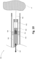
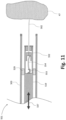
- a fourth embodiment of a surgical device 401 is shown in figures 9 and 10 .
- the surgical device 401 is similar to the surgical device 301 and includes a guide tube 403, a bearing 429, and a translational rod 419 that moves along linear motion 437.
- the translational rod 419 is connected to the needle 402.
- the needle 402 is not directly connected to the translational rod 419. Instead, the translational forces of the translational rod 419 and transferred via a spring 451 and piston cylinder 450 onto the needle 402.
- the spring 451 and the cylinder 450 are arranged within a cavity 452 of the translational rod 419.
- the spring 451 and the cylinder 450 may be simply arranged at the end of the translational rod 419.
- the needle 402 follows the movement of the translational rod 419. However, in case the needle 402 collides with a hard object, the spring 451 is compressed and absorbs the excessive forces (see figure 10 ). Additionally, a damping element may be included in parallel or series with the spring in order to prevent unwanted oscillations of the spring 451.
- the spring may be formed by an elastically deformable rod (e.g. a nitinol band).
- a fifth embodiment of a surgical device 501 is shown in figure 11 .
- the surgical device 501 may be similar to the surgical device 401 shown in figures 9 and 10 .
- the translational rod 519 is connected to the needle 502 with a connection rod 554 and a predetermined breaking point 553.
- the connection rod 552 may be an elastically deformable rod that is coupled to an element featuring a predetermined breaking point 553.
- the predetermined breaking point 553 may be formed by means known in the art e.g. by using edges, ridges or different materials. If the needle 502 collides with bony tissue 47, the connection rod 554 is deflected. Due to the deflection, translational forces are converted to shear forces on the predetermined breaking point 553. The higher the deflection of the rod, the higher the shear forces on the predetermined breaking point 553, which is consequently more likely to break.
Landscapes
- Health & Medical Sciences (AREA)
- Life Sciences & Earth Sciences (AREA)
- Surgery (AREA)
- Molecular Biology (AREA)
- General Health & Medical Sciences (AREA)
- Biomedical Technology (AREA)
- Heart & Thoracic Surgery (AREA)
- Medical Informatics (AREA)
- Nuclear Medicine, Radiotherapy & Molecular Imaging (AREA)
- Animal Behavior & Ethology (AREA)
- Engineering & Computer Science (AREA)
- Public Health (AREA)
- Veterinary Medicine (AREA)
- Pathology (AREA)
- Oral & Maxillofacial Surgery (AREA)
- Surgical Instruments (AREA)
- Prostheses (AREA)
Claims (13)
- Dispositif chirurgical (1) pour le feutrage d'un implant sur un tissu mou (46) d'un patient, comprenant au moins une aiguille de feutrage (2) prévue pour se déplacer en va-et-vient, et une interface de connexion (128 ; 135) pour connecter ladite au moins une aiguille de feutrage à un actionneur et pour transférer un mouvement en va-et-vient de l'interface (128 ; 135) à ladite au moins une aiguille de feutrage (2),
caractérisé en ce que ledit dispositif comprend un mécanisme de protection d'aiguille (3 ; 20 ; 135 ; 242 ; 331; 451 ; 553), ledit mécanisme de protection d'aiguille étant prévu pour empêcher ladite au moins une aiguille de feutrage d'être endommagée par contact avec une structure rigide pendant le mouvement en va-et-vient, comprenant un accouplement (128 ; 235) adapté pour transférer un mouvement en va-et-vient de l'actionneur (8) à ladite au moins une aiguille de feutrage (2), et ledit mécanisme de protection d'aiguille étant adapté pour découpler l'aiguille de feutrage (2) de l'actionneur (8) lorsqu'une force seuil ou un moment couple seuil sont dépassés, afin d'empêcher l'aiguille de feutrage d'être endommagée en découplant le couplage. - Dispositif chirurgical (1) selon la revendication 1, où ladite au moins une aiguille de feutrage a une largeur ou un diamètre inférieur à 0,8 mm.
- Dispositif chirurgical (1) selon l'une des revendications précédentes, où le mécanisme de protection d'aiguille comprend une pièce d'écartement (3, 20) destinée à entrer en contact avec le tissu, de manière à définir par la pièce d'écartement une profondeur de pénétration prédéterminée pour ladite au moins une aiguille.
- Dispositif chirurgical (1) selon la revendication 3, où la pièce d'écartement (3 ; 20) comprend un ou plusieurs doigts (20), ledit un ou plusieurs doigts présentant une surface d'extrémité distale pour entrer en contact avec le tissu de sorte que le mouvement en va-et-vient de l'aiguille de feutrage ne dépasse pas la profondeur de pénétration prédéterminée.
- Dispositif chirurgical (1) selon la revendication 4, où la pièce d'écartement (20) forme une glissière permettant à l'aiguille de feutrage d'être glissée le long d'une surface du tissu mou.
- Dispositif chirurgical (1) selon l'une des revendications précédentes, où ladite au moins une aiguille de feutrage présente une profondeur de pénétration maximale (16) et où ladite profondeur de pénétration maximale est réglable.
- Dispositif chirurgical (1) selon l'une des revendications précédentes, où le mécanisme de protection d'aiguille comprend un capteur de collision d'aiguille (331).
- Dispositif chirurgical (1) selon la revendication 7, où le capteur de collision d'aiguille est prévu pour mesurer une flexion de ladite au moins une aiguille de feutrage (2).
- Dispositif chirurgical (1) selon la revendication 7 ou la revendication 8, où ledit dispositif chirurgical comprend un contrôleur, où ledit contrôleur est prévu pour régler la profondeur de pénétration (16) de ladite au moins une aiguille de feutrage sur la base d'une mesure du capteur de collision d'aiguille (331).
- Dispositif chirurgical (1) selon l'une des revendications précédentes, où le mécanisme de protection d'aiguille comprend un embrayage à glissement (235), ledit embrayage à glissement (235) glisse au moins partiellement lorsque la force seuil ou le couple seuil appliqués sur ladite au moins une aiguille de feutrage sont dépassés.
- Dispositif chirurgical (1) selon la revendication 10, où l'embrayage à glissement comprend au moins l'un des éléments suivants : une goupille et une face chanfreinée ; un ressort à bille et une entaille correspondante pour recevoir la bille ; et un palier à ressort pour ladite au moins une aiguille de feutrage.
- Dispositif chirurgical (1) selon l'une des revendications précédentes, où le mécanisme de protection d'aiguille présente un point de rupture prédéterminé, ledit point de rupture prédéterminé subissant une rupture lorsqu'une force exercée sur ladite au moins une aiguille de feutrage dépasse un seuil prédéterminé.
- Système (1), comprenant un dispositif chirurgical selon l'une des revendications précédentes, et l'actionneur (8) pour entraîner ladite au moins une aiguille de feutrage avec un mouvement en va-et-vient.
Applications Claiming Priority (1)
| Application Number | Priority Date | Filing Date | Title |
|---|---|---|---|
| PCT/EP2020/081887 WO2022100833A1 (fr) | 2020-11-12 | 2020-11-12 | Dispositif chirurgical, système, et procédé de fabrication d'un dispositif chirurgical |
Publications (2)
| Publication Number | Publication Date |
|---|---|
| EP4243702A1 EP4243702A1 (fr) | 2023-09-20 |
| EP4243702B1 true EP4243702B1 (fr) | 2025-05-14 |
Family
ID=73401524
Family Applications (1)
| Application Number | Title | Priority Date | Filing Date |
|---|---|---|---|
| EP20806997.1A Active EP4243702B1 (fr) | 2020-11-12 | 2020-11-12 | Dispositif chirurgical et système |
Country Status (7)
| Country | Link |
|---|---|
| US (1) | US20240008897A1 (fr) |
| EP (1) | EP4243702B1 (fr) |
| JP (1) | JP7737650B2 (fr) |
| CN (1) | CN116419719A (fr) |
| AU (1) | AU2020476670B2 (fr) |
| CA (1) | CA3198576A1 (fr) |
| WO (1) | WO2022100833A1 (fr) |
Families Citing this family (6)
| Publication number | Priority date | Publication date | Assignee | Title |
|---|---|---|---|---|
| EP4186442B1 (fr) | 2021-11-30 | 2024-08-21 | ZuriMED Technologies AG | Dispositif chirurgical avec fil de bouclage |
| EP4424247A1 (fr) | 2023-03-02 | 2024-09-04 | ZuriMED Technologies AG | Dispositif chirurgical comprenant une aiguille de feutrage à pointe flexible |
| EP4424248A1 (fr) | 2023-03-02 | 2024-09-04 | ZuriMED Technologies AG | Dispositif chirurgical comprenant une aiguille de feutrage à pointe émoussée |
| TW202442196A (zh) | 2023-03-07 | 2024-11-01 | 瑞士商蘇黎醫藥科技股份有限公司 | 手術裝置 |
| EP4656159A1 (fr) | 2024-05-31 | 2025-12-03 | ZuriMED Technologies AG | Dispositif de pose, système comprenant le dispositif de pose et procédé de chargement d'un implant en forme de feuille flexible dans un dispositif de pose |
| CN121370349B (zh) * | 2025-12-23 | 2026-04-17 | 上海魅丽纬叶医疗科技股份公司 | 一种手柄及消融导管 |
Citations (2)
| Publication number | Priority date | Publication date | Assignee | Title |
|---|---|---|---|---|
| WO2016044762A1 (fr) * | 2014-09-18 | 2016-03-24 | Humacyte, Inc. | Procédés et appareils pour former des tubes fibreux |
| US20170312079A1 (en) * | 2016-04-28 | 2017-11-02 | Warsaw Orthopedic, Inc. | Mechanically entangled demineralized bone fibers |
Family Cites Families (10)
| Publication number | Priority date | Publication date | Assignee | Title |
|---|---|---|---|---|
| US20070106307A1 (en) * | 2005-09-30 | 2007-05-10 | Restoration Robotics, Inc. | Methods for implanting follicular units using an automated system |
| US7803136B2 (en) * | 2006-06-05 | 2010-09-28 | Schatz Richard A | Myocardial injector |
| US20100145306A1 (en) * | 2008-07-24 | 2010-06-10 | Boston Scientific Scimed, Inc. | Various Catheter Devices for Myocardial Injections or Other Uses |
| US8454494B2 (en) * | 2009-12-14 | 2013-06-04 | Ethicon Endo-Surgery, Inc. | Support apparatus for gastric band system injector |
| US9504479B2 (en) * | 2013-03-11 | 2016-11-29 | Eca Medical Instruments | Co-axial hot swappable system for minimally invasive medical procedures |
| CN105792877B (zh) * | 2013-09-30 | 2019-09-27 | 比尔卡地亚股份有限公司 | 桡动脉及经心内膜递送导管 |
| EP3066999A1 (fr) * | 2015-03-11 | 2016-09-14 | Richard A. Schatz | Barrière d'insertion d'une aiguille d'injection |
| US10639027B2 (en) * | 2015-10-27 | 2020-05-05 | Ethicon Llc | Suturing instrument cartridge with torque limiting features |
| US20180085143A1 (en) * | 2016-09-29 | 2018-03-29 | James B. DeYarman | Apparatus for hair transplantation |
| CN119587097A (zh) * | 2019-05-15 | 2025-03-11 | 苏黎世医疗科技有限公司 | 用于修复或加强人或动物软组织的方法的毡材料 |
-
2020
- 2020-11-12 US US18/252,653 patent/US20240008897A1/en active Pending
- 2020-11-12 AU AU2020476670A patent/AU2020476670B2/en active Active
- 2020-11-12 WO PCT/EP2020/081887 patent/WO2022100833A1/fr not_active Ceased
- 2020-11-12 JP JP2023528572A patent/JP7737650B2/ja active Active
- 2020-11-12 EP EP20806997.1A patent/EP4243702B1/fr active Active
- 2020-11-12 CA CA3198576A patent/CA3198576A1/fr active Pending
- 2020-11-12 CN CN202080107091.2A patent/CN116419719A/zh active Pending
Patent Citations (2)
| Publication number | Priority date | Publication date | Assignee | Title |
|---|---|---|---|---|
| WO2016044762A1 (fr) * | 2014-09-18 | 2016-03-24 | Humacyte, Inc. | Procédés et appareils pour former des tubes fibreux |
| US20170312079A1 (en) * | 2016-04-28 | 2017-11-02 | Warsaw Orthopedic, Inc. | Mechanically entangled demineralized bone fibers |
Also Published As
| Publication number | Publication date |
|---|---|
| AU2020476670A9 (en) | 2025-01-09 |
| AU2020476670A1 (en) | 2023-06-15 |
| CN116419719A (zh) | 2023-07-11 |
| EP4243702A1 (fr) | 2023-09-20 |
| AU2020476670B2 (en) | 2024-09-26 |
| WO2022100833A1 (fr) | 2022-05-19 |
| CA3198576A1 (fr) | 2022-05-19 |
| US20240008897A1 (en) | 2024-01-11 |
| JP7737650B2 (ja) | 2025-09-11 |
| JP2023549834A (ja) | 2023-11-29 |
Similar Documents
| Publication | Publication Date | Title |
|---|---|---|
| EP4243702B1 (fr) | Dispositif chirurgical et système | |
| KR101527734B1 (ko) | 가요성 내시경적 봉합사 앵커 어플라이어 | |
| US20200054315A1 (en) | Methods and devices to decrease tissue trauma during surgery | |
| US9402610B2 (en) | Rib-protecting devices for thoracoscopic surgery, and related methods | |
| CN101534731B (zh) | 外科手术切割装置 | |
| EP2704641B1 (fr) | Réparation de ménisque | |
| EP4364695A1 (fr) | Pince de réparation de valvule avec confirmation de capture de feuillet | |
| US20050090840A1 (en) | Tissue repair | |
| US7866523B1 (en) | Soft-tipped anvil | |
| US20240148409A1 (en) | Systems, devices, and methods for creating curvilinear tunnels in bone | |
| AU2025287326A1 (en) | Meniscal repair delivery device | |
| JP7389489B2 (ja) | 負圧式把持システム、方法およびツール | |
| CN118234438A (zh) | 手术设备、预弯曲屈曲线的设备、将植入物毡合到软组织的方法和预弯曲屈曲线的方法 | |
| JP3898886B2 (ja) | 内視鏡 | |
| JP2002291688A (ja) | 内視鏡 | |
| EP4676345A1 (fr) | Dispositif chirurgical | |
| HK40051563A (en) | Medical device and method for performing a surgical operation in a body | |
| JP2002125924A (ja) | 内視鏡 |
Legal Events
| Date | Code | Title | Description |
|---|---|---|---|
| STAA | Information on the status of an ep patent application or granted ep patent |
Free format text: STATUS: UNKNOWN |
|
| STAA | Information on the status of an ep patent application or granted ep patent |
Free format text: STATUS: THE INTERNATIONAL PUBLICATION HAS BEEN MADE |
|
| PUAI | Public reference made under article 153(3) epc to a published international application that has entered the european phase |
Free format text: ORIGINAL CODE: 0009012 |
|
| STAA | Information on the status of an ep patent application or granted ep patent |
Free format text: STATUS: REQUEST FOR EXAMINATION WAS MADE |
|
| 17P | Request for examination filed |
Effective date: 20230502 |
|
| AK | Designated contracting states |
Kind code of ref document: A1 Designated state(s): AL AT BE BG CH CY CZ DE DK EE ES FI FR GB GR HR HU IE IS IT LI LT LU LV MC MK MT NL NO PL PT RO RS SE SI SK SM TR |
|
| DAV | Request for validation of the european patent (deleted) | ||
| DAX | Request for extension of the european patent (deleted) | ||
| STAA | Information on the status of an ep patent application or granted ep patent |
Free format text: STATUS: EXAMINATION IS IN PROGRESS |
|
| 17Q | First examination report despatched |
Effective date: 20240514 |
|
| REG | Reference to a national code |
Ref country code: DE Ref legal event code: R079 Free format text: PREVIOUS MAIN CLASS: A61B0017040000 Ref country code: DE Ref legal event code: R079 Ref document number: 602020051333 Country of ref document: DE Free format text: PREVIOUS MAIN CLASS: A61B0017040000 Ipc: A61B0017062000 |
|
| GRAP | Despatch of communication of intention to grant a patent |
Free format text: ORIGINAL CODE: EPIDOSNIGR1 |
|
| STAA | Information on the status of an ep patent application or granted ep patent |
Free format text: STATUS: GRANT OF PATENT IS INTENDED |
|
| RIC1 | Information provided on ipc code assigned before grant |
Ipc: A61B 17/00 20060101ALI20241103BHEP Ipc: A61B 90/00 20160101ALI20241103BHEP Ipc: A61B 17/04 20060101ALI20241103BHEP Ipc: A61B 17/06 20060101ALI20241103BHEP Ipc: A61B 17/062 20060101AFI20241103BHEP |
|
| INTG | Intention to grant announced |
Effective date: 20241120 |
|
| GRAS | Grant fee paid |
Free format text: ORIGINAL CODE: EPIDOSNIGR3 |
|
| P01 | Opt-out of the competence of the unified patent court (upc) registered |
Free format text: CASE NUMBER: APP_6398/2025 Effective date: 20250206 |
|
| RIN1 | Information on inventor provided before grant (corrected) |
Inventor name: BANZET, POL Inventor name: LI, XIANG Inventor name: BACHMANN, ELIAS |
|
| GRAA | (expected) grant |
Free format text: ORIGINAL CODE: 0009210 |
|
| STAA | Information on the status of an ep patent application or granted ep patent |
Free format text: STATUS: THE PATENT HAS BEEN GRANTED |
|
| AK | Designated contracting states |
Kind code of ref document: B1 Designated state(s): AL AT BE BG CH CY CZ DE DK EE ES FI FR GB GR HR HU IE IS IT LI LT LU LV MC MK MT NL NO PL PT RO RS SE SI SK SM TR |
|
| REG | Reference to a national code |
Ref country code: GB Ref legal event code: FG4D |
|
| REG | Reference to a national code |
Ref country code: CH Ref legal event code: EP |
|
| REG | Reference to a national code |
Ref country code: DE Ref legal event code: R096 Ref document number: 602020051333 Country of ref document: DE |
|
| REG | Reference to a national code |
Ref country code: IE Ref legal event code: FG4D |
|
| REG | Reference to a national code |
Ref country code: NL Ref legal event code: MP Effective date: 20250514 |
|
| PG25 | Lapsed in a contracting state [announced via postgrant information from national office to epo] |
Ref country code: PT Free format text: LAPSE BECAUSE OF FAILURE TO SUBMIT A TRANSLATION OF THE DESCRIPTION OR TO PAY THE FEE WITHIN THE PRESCRIBED TIME-LIMIT Effective date: 20250915 Ref country code: FI Free format text: LAPSE BECAUSE OF FAILURE TO SUBMIT A TRANSLATION OF THE DESCRIPTION OR TO PAY THE FEE WITHIN THE PRESCRIBED TIME-LIMIT Effective date: 20250514 Ref country code: ES Free format text: LAPSE BECAUSE OF FAILURE TO SUBMIT A TRANSLATION OF THE DESCRIPTION OR TO PAY THE FEE WITHIN THE PRESCRIBED TIME-LIMIT Effective date: 20250514 |
|
| REG | Reference to a national code |
Ref country code: LT Ref legal event code: MG9D |
|
| PG25 | Lapsed in a contracting state [announced via postgrant information from national office to epo] |
Ref country code: NO Free format text: LAPSE BECAUSE OF FAILURE TO SUBMIT A TRANSLATION OF THE DESCRIPTION OR TO PAY THE FEE WITHIN THE PRESCRIBED TIME-LIMIT Effective date: 20250814 Ref country code: GR Free format text: LAPSE BECAUSE OF FAILURE TO SUBMIT A TRANSLATION OF THE DESCRIPTION OR TO PAY THE FEE WITHIN THE PRESCRIBED TIME-LIMIT Effective date: 20250815 |
|
| PG25 | Lapsed in a contracting state [announced via postgrant information from national office to epo] |
Ref country code: NL Free format text: LAPSE BECAUSE OF FAILURE TO SUBMIT A TRANSLATION OF THE DESCRIPTION OR TO PAY THE FEE WITHIN THE PRESCRIBED TIME-LIMIT Effective date: 20250514 Ref country code: PL Free format text: LAPSE BECAUSE OF FAILURE TO SUBMIT A TRANSLATION OF THE DESCRIPTION OR TO PAY THE FEE WITHIN THE PRESCRIBED TIME-LIMIT Effective date: 20250514 |
|
| REG | Reference to a national code |
Ref country code: AT Ref legal event code: MK05 Ref document number: 1794141 Country of ref document: AT Kind code of ref document: T Effective date: 20250514 |
|
| PG25 | Lapsed in a contracting state [announced via postgrant information from national office to epo] |
Ref country code: BG Free format text: LAPSE BECAUSE OF FAILURE TO SUBMIT A TRANSLATION OF THE DESCRIPTION OR TO PAY THE FEE WITHIN THE PRESCRIBED TIME-LIMIT Effective date: 20250514 |
|
| PG25 | Lapsed in a contracting state [announced via postgrant information from national office to epo] |
Ref country code: HR Free format text: LAPSE BECAUSE OF FAILURE TO SUBMIT A TRANSLATION OF THE DESCRIPTION OR TO PAY THE FEE WITHIN THE PRESCRIBED TIME-LIMIT Effective date: 20250514 |
|
| PG25 | Lapsed in a contracting state [announced via postgrant information from national office to epo] |
Ref country code: AT Free format text: LAPSE BECAUSE OF FAILURE TO SUBMIT A TRANSLATION OF THE DESCRIPTION OR TO PAY THE FEE WITHIN THE PRESCRIBED TIME-LIMIT Effective date: 20250514 |
|
| PG25 | Lapsed in a contracting state [announced via postgrant information from national office to epo] |
Ref country code: RS Free format text: LAPSE BECAUSE OF FAILURE TO SUBMIT A TRANSLATION OF THE DESCRIPTION OR TO PAY THE FEE WITHIN THE PRESCRIBED TIME-LIMIT Effective date: 20250814 |
|
| PG25 | Lapsed in a contracting state [announced via postgrant information from national office to epo] |
Ref country code: IS Free format text: LAPSE BECAUSE OF FAILURE TO SUBMIT A TRANSLATION OF THE DESCRIPTION OR TO PAY THE FEE WITHIN THE PRESCRIBED TIME-LIMIT Effective date: 20250914 |
|
| PG25 | Lapsed in a contracting state [announced via postgrant information from national office to epo] |
Ref country code: LV Free format text: LAPSE BECAUSE OF FAILURE TO SUBMIT A TRANSLATION OF THE DESCRIPTION OR TO PAY THE FEE WITHIN THE PRESCRIBED TIME-LIMIT Effective date: 20250514 |
|
| REG | Reference to a national code |
Ref country code: CH Ref legal event code: U11 Free format text: ST27 STATUS EVENT CODE: U-0-0-U10-U11 (AS PROVIDED BY THE NATIONAL OFFICE) Effective date: 20251201 |
|
| PGFP | Annual fee paid to national office [announced via postgrant information from national office to epo] |
Ref country code: DE Payment date: 20251128 Year of fee payment: 6 |
|
| PGFP | Annual fee paid to national office [announced via postgrant information from national office to epo] |
Ref country code: GB Payment date: 20251127 Year of fee payment: 6 |
|
| PG25 | Lapsed in a contracting state [announced via postgrant information from national office to epo] |
Ref country code: DK Free format text: LAPSE BECAUSE OF FAILURE TO SUBMIT A TRANSLATION OF THE DESCRIPTION OR TO PAY THE FEE WITHIN THE PRESCRIBED TIME-LIMIT Effective date: 20250514 Ref country code: SM Free format text: LAPSE BECAUSE OF FAILURE TO SUBMIT A TRANSLATION OF THE DESCRIPTION OR TO PAY THE FEE WITHIN THE PRESCRIBED TIME-LIMIT Effective date: 20250514 |
|
| PGFP | Annual fee paid to national office [announced via postgrant information from national office to epo] |
Ref country code: FR Payment date: 20251124 Year of fee payment: 6 |
|
| PGFP | Annual fee paid to national office [announced via postgrant information from national office to epo] |
Ref country code: CH Payment date: 20251201 Year of fee payment: 6 |
|
| PG25 | Lapsed in a contracting state [announced via postgrant information from national office to epo] |
Ref country code: CZ Free format text: LAPSE BECAUSE OF FAILURE TO SUBMIT A TRANSLATION OF THE DESCRIPTION OR TO PAY THE FEE WITHIN THE PRESCRIBED TIME-LIMIT Effective date: 20250514 |
|
| PG25 | Lapsed in a contracting state [announced via postgrant information from national office to epo] |
Ref country code: EE Free format text: LAPSE BECAUSE OF FAILURE TO SUBMIT A TRANSLATION OF THE DESCRIPTION OR TO PAY THE FEE WITHIN THE PRESCRIBED TIME-LIMIT Effective date: 20250514 |
|
| PG25 | Lapsed in a contracting state [announced via postgrant information from national office to epo] |
Ref country code: SK Free format text: LAPSE BECAUSE OF FAILURE TO SUBMIT A TRANSLATION OF THE DESCRIPTION OR TO PAY THE FEE WITHIN THE PRESCRIBED TIME-LIMIT Effective date: 20250514 |
|
| PG25 | Lapsed in a contracting state [announced via postgrant information from national office to epo] |
Ref country code: IT Free format text: LAPSE BECAUSE OF FAILURE TO SUBMIT A TRANSLATION OF THE DESCRIPTION OR TO PAY THE FEE WITHIN THE PRESCRIBED TIME-LIMIT Effective date: 20250514 |
|
| REG | Reference to a national code |
Ref country code: DE Ref legal event code: R097 Ref document number: 602020051333 Country of ref document: DE |
|
| PG25 | Lapsed in a contracting state [announced via postgrant information from national office to epo] |
Ref country code: RO Free format text: LAPSE BECAUSE OF FAILURE TO SUBMIT A TRANSLATION OF THE DESCRIPTION OR TO PAY THE FEE WITHIN THE PRESCRIBED TIME-LIMIT Effective date: 20250514 |
|
| PLBE | No opposition filed within time limit |
Free format text: ORIGINAL CODE: 0009261 |
|
| STAA | Information on the status of an ep patent application or granted ep patent |
Free format text: STATUS: NO OPPOSITION FILED WITHIN TIME LIMIT |
|
| REG | Reference to a national code |
Ref country code: CH Ref legal event code: L10 Free format text: ST27 STATUS EVENT CODE: U-0-0-L10-L00 (AS PROVIDED BY THE NATIONAL OFFICE) Effective date: 20260325 |
|
| 26N | No opposition filed |
Effective date: 20260217 |