EP4244467B1 - Hybridantriebsturbomaschine und flugzeug mit solch einer turbomaschine - Google Patents
Hybridantriebsturbomaschine und flugzeug mit solch einer turbomaschine Download PDFInfo
- Publication number
- EP4244467B1 EP4244467B1 EP21815247.8A EP21815247A EP4244467B1 EP 4244467 B1 EP4244467 B1 EP 4244467B1 EP 21815247 A EP21815247 A EP 21815247A EP 4244467 B1 EP4244467 B1 EP 4244467B1
- Authority
- EP
- European Patent Office
- Prior art keywords
- turbomachine
- propeller
- oil pump
- circuit
- converter
- Prior art date
- Legal status (The legal status is an assumption and is not a legal conclusion. Google has not performed a legal analysis and makes no representation as to the accuracy of the status listed.)
- Active
Links
Images


Classifications
-
- F—MECHANICAL ENGINEERING; LIGHTING; HEATING; WEAPONS; BLASTING
- F02—COMBUSTION ENGINES; HOT-GAS OR COMBUSTION-PRODUCT ENGINE PLANTS
- F02C—GAS-TURBINE PLANTS; AIR INTAKES FOR JET-PROPULSION PLANTS; CONTROLLING FUEL SUPPLY IN AIR-BREATHING JET-PROPULSION PLANTS
- F02C6/00—Plural gas-turbine plants; Combinations of gas-turbine plants with other apparatus; Adaptations of gas-turbine plants for special use
- F02C6/20—Adaptations of gas-turbine plants for driving vehicles
- F02C6/206—Adaptations of gas-turbine plants for driving vehicles the vehicles being airscrew driven
-
- F—MECHANICAL ENGINEERING; LIGHTING; HEATING; WEAPONS; BLASTING
- F01—MACHINES OR ENGINES IN GENERAL; ENGINE PLANTS IN GENERAL; STEAM ENGINES
- F01D—NON-POSITIVE DISPLACEMENT MACHINES OR ENGINES, e.g. STEAM TURBINES
- F01D15/00—Adaptations of machines or engines for special use; Combinations of engines with devices driven thereby
- F01D15/10—Adaptations for driving, or combinations with, electric generators
-
- F—MECHANICAL ENGINEERING; LIGHTING; HEATING; WEAPONS; BLASTING
- F02—COMBUSTION ENGINES; HOT-GAS OR COMBUSTION-PRODUCT ENGINE PLANTS
- F02C—GAS-TURBINE PLANTS; AIR INTAKES FOR JET-PROPULSION PLANTS; CONTROLLING FUEL SUPPLY IN AIR-BREATHING JET-PROPULSION PLANTS
- F02C7/00—Features, components parts, details or accessories, not provided for in, or of interest apart form groups F02C1/00 - F02C6/00; Air intakes for jet-propulsion plants
- F02C7/06—Arrangements of bearings; Lubricating
-
- F—MECHANICAL ENGINEERING; LIGHTING; HEATING; WEAPONS; BLASTING
- F02—COMBUSTION ENGINES; HOT-GAS OR COMBUSTION-PRODUCT ENGINE PLANTS
- F02C—GAS-TURBINE PLANTS; AIR INTAKES FOR JET-PROPULSION PLANTS; CONTROLLING FUEL SUPPLY IN AIR-BREATHING JET-PROPULSION PLANTS
- F02C7/00—Features, components parts, details or accessories, not provided for in, or of interest apart form groups F02C1/00 - F02C6/00; Air intakes for jet-propulsion plants
- F02C7/32—Arrangement, mounting, or driving, of auxiliaries
-
- F—MECHANICAL ENGINEERING; LIGHTING; HEATING; WEAPONS; BLASTING
- F05—INDEXING SCHEMES RELATING TO ENGINES OR PUMPS IN VARIOUS SUBCLASSES OF CLASSES F01-F04
- F05D—INDEXING SCHEME FOR ASPECTS RELATING TO NON-POSITIVE-DISPLACEMENT MACHINES OR ENGINES, GAS-TURBINES OR JET-PROPULSION PLANTS
- F05D2220/00—Application
- F05D2220/30—Application in turbines
- F05D2220/32—Application in turbines in gas turbines
- F05D2220/323—Application in turbines in gas turbines for aircraft propulsion, e.g. jet engines
-
- F—MECHANICAL ENGINEERING; LIGHTING; HEATING; WEAPONS; BLASTING
- F05—INDEXING SCHEMES RELATING TO ENGINES OR PUMPS IN VARIOUS SUBCLASSES OF CLASSES F01-F04
- F05D—INDEXING SCHEME FOR ASPECTS RELATING TO NON-POSITIVE-DISPLACEMENT MACHINES OR ENGINES, GAS-TURBINES OR JET-PROPULSION PLANTS
- F05D2220/00—Application
- F05D2220/70—Application in combination with
- F05D2220/76—Application in combination with an electrical generator
-
- F—MECHANICAL ENGINEERING; LIGHTING; HEATING; WEAPONS; BLASTING
- F05—INDEXING SCHEMES RELATING TO ENGINES OR PUMPS IN VARIOUS SUBCLASSES OF CLASSES F01-F04
- F05D—INDEXING SCHEME FOR ASPECTS RELATING TO NON-POSITIVE-DISPLACEMENT MACHINES OR ENGINES, GAS-TURBINES OR JET-PROPULSION PLANTS
- F05D2260/00—Function
- F05D2260/98—Lubrication
-
- Y—GENERAL TAGGING OF NEW TECHNOLOGICAL DEVELOPMENTS; GENERAL TAGGING OF CROSS-SECTIONAL TECHNOLOGIES SPANNING OVER SEVERAL SECTIONS OF THE IPC; TECHNICAL SUBJECTS COVERED BY FORMER USPC CROSS-REFERENCE ART COLLECTIONS [XRACs] AND DIGESTS
- Y02—TECHNOLOGIES OR APPLICATIONS FOR MITIGATION OR ADAPTATION AGAINST CLIMATE CHANGE
- Y02T—CLIMATE CHANGE MITIGATION TECHNOLOGIES RELATED TO TRANSPORTATION
- Y02T50/00—Aeronautics or air transport
- Y02T50/60—Efficient propulsion technologies, e.g. for aircraft
Definitions
- the invention relates to the field of turbomachines.
- the invention more specifically relates to a turbomachine and an aircraft comprising such a turbomachine.
- a turboprop comprises a propeller, a propeller shaft carrying the propeller, the rotating electrical machine which has at least a first configuration in which it is mechanically coupled to the propeller shaft and makes it possible to drive the propeller shaft in rotation when it is supplied with current.
- the invention aims to remedy this drawback and thus aims to provide a turbomachine comprising a rotating electric machine which has a more suitable electric propulsion function.
- the invention relates to this purpose to a turbomachine comprising a propeller, a propeller shaft carrying the propeller, a rotating electrical machine, having at least a first configuration in which it is mechanically coupled to the propeller shaft, and an engine oil pump supplying a lubrication circuit of the turbomachine, the rotating electrical machine being capable of rotating the propeller shaft when it is supplied with current in the at least one first configuration.
- the rotating electrical machine in the first configuration is mechanically coupled to the engine oil pump in such a manner that the rotating electrical machine additionally drives the engine oil pump when supplied with current.
- the lubrication functions and the other functions associated with the engine oil pump are retained when the rotating electrical machine is in the first configuration and provides electric propulsion of the turbomachine.
- the other ancillary functions provided by the hydraulic force of the oil circuit such as the control of the propeller pitch in the context of a variable-pitch propeller, are also functional during electric propulsion in the context of such a turbomachine.
- the lubrication functions and these ancillary functions can be provided in the absence of operation of the gas turbine, the latter does not have to be kept running unlike the turbomachines of the prior art.
- the electric propulsion function enabled by the rotating electrical machine according to the invention is particularly suitable.
- the turbomachine can be a turboprop or a turboshaft engine of the tilting rotor type, better known by the English name “Proprotor”.
- propulsion by the rotating electric machine, or “electric propulsion”
- drive by the rotating electric machine or electric drive
- propulsion having been chosen for simplification since the invention relates in particular to turboprops for which it is effectively a question of "propulsion” by the rotating electric machine and of "electric propulsion".
- the rotating electrical machine can be mechanically coupled to the engine oil pump by means of at least a first freewheel.
- the engine oil pump can be driven both by the rotating electric machine and by a high-pressure turbine of a gas turbine without risk of damage, since the movement of the engine oil pump can be decorrelated from that of the rotating electric machine by the first freewheel.
- the turbomachine may further comprise a gas turbine comprising a high-pressure turbine, the engine oil pump being mechanically coupled to the high-pressure turbine by means of a second freewheel so as to allow the engine oil pump to be driven both by the rotating electrical machine in at least its first configuration and by the high-pressure turbine.
- the engine oil pump can be driven by the rotating electric machine without rotating the high-pressure turbine. In this way, the load applied to the rotating machine is reduced and the power of the rotating electric machine required to rotate the engine oil pump is reduced.
- the engine oil pump can be driven both by the rotating electric machine and by the high-pressure turbine and thus ensure good lubrication of the turbomachine regardless of the source of propulsion.
- the propeller may be a variable pitch propeller and may be connected to the lubrication circuit by a propeller control unit in such a manner as to allow adjustment of the propeller pitch from an oil pressure applied to it by the propeller control unit.
- turbomachine comprising such a propeller particularly benefits from the invention since the oil pressure supplied by the engine oil pump makes it possible to control the pitch of the propeller even when the gas turbine is off and the propulsion is provided by the rotating electric machine.
- the propeller drive unit may include an additional oil pump for raising the oil pressure provided by the engine oil pump and wherein the additional oil pump is mechanically coupled to the propeller shaft such that rotation of the propeller shaft drives the additional oil pump.
- the additional oil pump is driven by the propeller shaft whether the propulsion is electric or conventional.
- the turbomachine may be a free turbine turbomachine, the turbomachine further comprising a gas turbine comprising a free turbine, and the propeller shaft being mechanically coupled to the free turbine by means of a third freewheel.
- the propeller shaft can be rotated without the free turbine also being rotated, thereby reducing the power to be supplied by the rotating electrical machine to rotate the propeller shaft.
- the invention further relates to an aircraft comprising a turbomachine according to the invention and at least one DC circuit connected to the rotating electrical machine of each turboprop by means of an AC/DC converter of said turbomachine.
- the DC circuit may include a first low voltage subcircuit and a second high voltage subcircuit connected to each other by a DC/DC converter and the AC/DC converter of the or each turboprop being connected to the DC circuit by the second sub-circuit.
- the DC/DC converter may comprise a resonant transformer, the DC/DC converter preferably comprising a low-pass filtration stage at the interface with the first sub-circuit.
- Such a resonant transformer allows the provision of an efficient DC/DC transformation while providing good galvanic isolation.
- the second subcircuit may comprise at least one HVDC type battery, the second subcircuit further preferably comprising a DC/DC converter in order to adapt the voltage delivered by the HVDC type battery to that of the second subcircuit.
- turbomachine here a turboprop 10
- a turbomachine 19 capable of providing a generator function and a propulsion function, in particular in the context of taxiing-type movement.
- the turbomachine 1 is a free turbine turboprop.
- a gas turbine 11 comprises, as a result, a high-pressure turbine, not referenced, rotating a turbine shaft 14 and a compressor, not referenced, and a free turbine 111 which drives a secondary shaft, not referenced, of the gas turbine, concentric with the turbine shaft 14.
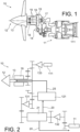
- the turboprop 10 thus comprises, as shown in the figure 1 , the gas turbine 11, a propeller 12, a propeller shaft 13, extending towards the gas turbine 11 and being coupled, as will be described later, to the free turbine 111 by means of a transmission.
- the free turbine 111 is rotatably mounted around a turbine shaft 14 of the high-pressure turbine.
- the propeller shaft 13 is surrounded by a protective casing 15. It is supported in the casing 15 by bearings 16 and 17.
- One of the bearings 16 is close to the propeller 12, and the other of the bearings 17 is adjacent to a toothed wheel 18 for driving the propeller shaft 13, which meshes with the above-mentioned transmission.
- the rotating electrical machine 19 is, in this example of the invention, arranged concentrically around the propeller shaft 13, between the first bearing 16 and the toothed wheel 18, being surrounded by the casing 15.
- the turbomachine is a “conventional” turboprop.
- the turbomachine may be a tilting rotor turbomachine, better known by the English name of “proprotor”, which is intended to equip a vertical take-off aircraft known by the English name of “tiltrotor”.
- the turbomachine may thus be both a turboprop and a turboshaft.
- the person skilled in the art is of course able to generalize the present teaching described for a “conventional” turboprop to these other types of turbomachines.
- the gas turbine 11 being of the free turbine type, it offers two means of driving the elements of the turboprop, the high-pressure turbine and its turbine shaft 14, and the free turbine 111 and its secondary shaft.
- the drive kinematics provided by the turbomachine in the context of the present embodiment of the invention, reference is made to the description of the figure 2 .
- turboprop 10 described above is in accordance with the teaching of the document FR 3057029 , it is not limited to this single configuration of the rotating electric machine 19 in which the rotating electric machine is arranged concentric with the propeller shaft 13.
- present teaching can easily be adapted to a remote configuration as taught by the document US 2017/321601 .
- the rotating electric machine 19 is, in the context of this embodiment, a simple rotating electric machine capable of providing a generator function and an electric propulsion function
- the rotating electric machine 19 can have additional functions, such as those of supplying a blade de-icing circuit according to the possibility taught by the document US 2019/233128 .
- the turboprop taught by the document FR 3057029 and that taught by the document US 2019/233128
- the person skilled in the art is perfectly able to apply the teaching of the document US 2019/233128 to the turboprop engine according to the present embodiment.
- the parts of the document US 2019/233128 related to the figure 2 corresponding to paragraphs [14] to [20] and the figure 2 are incorporated by reference into this document.
- the rotating electrical machine 19 has at least a first configuration in which it is mechanically coupled to the propeller shaft, and the turboprop 10 comprises an engine oil pump 21 which, as shown in the figure 2 , supplies a lubrication circuit 20 of the turboprop 10.
- the rotating electrical machine 19 is capable of rotating the propeller shaft 13 when it is supplied with current in the at least one first configuration.
- the rotating electrical machine 19 is mechanically coupled to the engine oil pump 21 in such a way that the rotating electrical machine 19 also drives the engine oil pump 21 when it is supplied with current.
- the drive of the engine oil pump allows oil to circulate in the lubrication circuit, allowing, in addition to the lubrication of the elements of the turboprop, such as the bearings and rollers 16 and 17 of the turboprop 10, to provide hydraulic pressure to all of the equipment of the turbomachine requiring it, such as for example a propeller control unit 121, as described below in connection with the figure 2 .
- the rotating electrical machine 19 is preferably a brushless rotating electrical machine, this to limit the risks of wear and maintenance of the turboprop 10, and can thus be either a permanent magnet synchronous rotating electrical machine or a variable reluctance synchronous rotating electrical machine, a wound rotor synchronous machine or even an asynchronous rotating electrical machine.
- this coupling can be intermittent, the rotating electric machine 19 having a second configuration in which it is decoupled both from the propeller shaft 13 and from the engine oil pump 21.
- Such a possibility of coupling/decoupling between the rotating electric machine 19 with the propeller shaft and the engine oil pump 21 can be achieved in accordance with the teaching of the document US 2017/321601 .
- the teaching of the document US 2017/321601 selective mating present in paragraphs [30] to [40] and the figure 1 associated is incorporated by reference into this document.
- the rotating electrical machine 19 is directly coupled to the propeller shaft 13, and therefore to the propeller 12 by means of a set of gears to achieve a speed adaptation between the rotating electrical machine 19 and the propeller shaft 13.
- the input gear of the propeller shaft 13 is also coupled to the free turbine 111 of the gas turbine 11, through a third freewheel 133, and to the propeller control unit 121.
- the free turbine 111 is artificially separated from the gas turbine, since the free turbine 111 is rotationally decoupled from the turbine shaft 14.
- the propeller control unit 121 and therefore the propeller shaft 13 and the rotating electrical machine 19, are also mechanically coupled to the engine oil pump 21 this through a first freewheel 131.
- the engine oil pump 21 is also mechanically coupled to the gas turbine 11, or more precisely to the high pressure turbine and to the turbine shaft 14, by means of a second freewheel 132.
- the rotating electrical machine 19 when supplied with current, it will be able to drive the propeller shaft 13 in rotation through its input gear.
- This same input gear drives the propeller control unit 121, and in particular an additional oil pump, not referenced, included by the propeller control unit 121, said additional oil pump being able to raise the oil pressure provided by the engine oil pump 21 through the oil network 20 to allow the hydraulic control of the pitch of the propeller when the latter is variable pitch through an oil subnetwork 25.
- the drive of the propeller control unit 121 also makes it possible to drive the engine oil pump 21, through the first freewheel 131, to supply the lubrication circuit 20 with oil.
- the second and third freewheels 132, 133 allow respective decoupling between the engine oil pump 21 and the turbine shaft 14 and between the propeller shaft 13 and the free turbine. In this way, since the elements of the gas turbine are not driven, the forces to be provided by the rotating electric machine 19 are reduced.
- the turbine shaft 14 allows, according to a usual operation of a turboprop, to drive the engine oil pump 21 through the second freewheel 132.
- the free turbine 111 drives the propeller shaft 13 by means of the third freewheel 133.
- This drive of the propeller shaft 13 also allows the drive of the propeller control unit.
- the rotating electrical machine 19 remains coupled to the propeller shaft 13, the possible selective decoupling not being implemented, the latter is also driven in rotation by the propeller shaft 13 and can therefore provide an electricity generating function.
- the first freewheel 131 allows the decoupling between the propeller shaft 13 and the engine oil pump 21 to be ensured in order to ensure that the drive of the latter is only provided by the turbine shaft 14 when the propulsion is provided by the gas turbine 11.
- FIG. 3 which schematizes the electrical circuit of an aircraft 1 comprising a plurality of turboprops 10 A , 10 B , 10 C , 10 N
- the rotating electrical machine 19 A , 19 B , 19 C , 19 N of each turboprop 10 A , 10 B , 10 C , 10 N is connected to a DC circuit 50 of the aircraft by means of an AC/DC converter 41 A , 41 B , 41 C , 41 N of said turboprop 10 A , 10 B , 10 C , 10 N.
- the AC/DC converter 41 A , 41 B , 41 C , 41 N may be of the inverter type in order to allow a conversion of the DC electric current supplied by the DC circuit 50 to the turboprop into AC current, when the electric propulsion function is implemented.
- the AC/DC converter 41 A , 41 B , 41 C , 41 N can also have a rectifier configuration in order to allow a conversion of the AC electric current supplied by the rotating electric machine 19 into DC current to power the DC circuit, when the generator function of the rotating electric machine 19 is implemented.
- the DC circuit 50 can comprise a first low-voltage sub-circuit 51 and a second high-voltage sub-circuit 52 connected to each other by a first DC/DC converter 55.
- the AC/DC converter 41 A , 41 B , 41 C , 41 N of each turboprop 10, 10 A , 10 B , 10 C , 10 N is connected to the DC circuit 50 by the second sub-circuit 52.
- the various equipment of the aircraft via a low voltage according to a usual configuration of aircraft, this generally being 28 V, and to use a higher voltage in the context of the supply of the various rotating electrical machines 19 A , 19 B , 19 C , 19 N in order to optimize the power accessible to rotating electrical machines 19 A , 19 B , 19 C , 19 N within the framework of the electric propulsion function, this voltage which may be, for example, equal to or greater than 270 V.
- the second subcircuit 52 forms a subcircuit of the HVDC type.
- first and fourth filtering stages 551, 555 are not necessarily necessary and that, in a simplified configuration of such a first DC/DC converter 55, it is possible not to provide them or, advantageously, to only provide the first filtering stage 551 so as to protect the first sub-circuit 51.
- the first filtering stage 551 comprises a first coil L 1 (current I 1 ) and a capacitor C 1 (current I C1 ).
- the second DC/AC converter stage 552 comprises four transistors T1, T2, T3, T4 configured to connect a first and a second output of the first filtering stage 551 alternately to respectively a first and a second input of the transformer 553 according to a double alternation switching also known under the English name of "full bridge".
- the second DC/AC converter stage 551 supplies/receives the current I red with the alternating voltage V AC1 .
- the transformer 553 comprises, in addition to the primary and secondary coils of the transformer, a second coil L 1 so as to equalize the resonant frequencies of the primary circuit and the secondary circuit.
- the transformer presents/receives at the input of the third reversible AC/DC converter stage 554 an alternating voltage V AC2 .
- the first third reversible AC/DC converter stage 554 comprises four transistors T1, T2, T3, T4 configured to connect a first and a second input of the fourth filtering stage 555 alternately to respectively a first and a second output of the transformer 553 according to a double alternation switching also known under the English name of "full bridge".
- the fourth filtering stage 555 thus receives the current I 2red and comprises a capacitor C 2 (current I C2 ) and makes it possible to supply/recover a voltage V 2 corresponding to the voltage of the second sub-circuit 52 of the DC circuit 50.
- first DC/DC converter 55 is provided as an example, other converter topographies are perfectly conceivable without departing from the scope of the invention, the converter preferably having to provide galvanic isolation in particular by means of a transformer which can advantageously be resonant.
- the first sub-circuit 51 may comprise, in addition to the DC/DC converter 55 which allows its connection to the second sub-circuit 52, a conventional battery system 56 allowing the power supply of the equipment of the aircraft 1 in the absence of current generation and a current generation system 57.
- the second sub-circuit 52 may further comprise a battery system 58 called an HVDC battery system capable of providing sufficient electrical power to allow movement of the aircraft 1 by means of the electric propulsion function offered by the rotating electrical machines 19 A , 19 B , 19 C , 19 N.
- the second sub-circuit may comprise a second DC/DC converter. This second DC/DC converter may be a buck-boost converter or only buck or boost depending on the voltage range expected at the output of the HVDC battery system 58.
Landscapes
- Engineering & Computer Science (AREA)
- Chemical & Material Sciences (AREA)
- Combustion & Propulsion (AREA)
- Mechanical Engineering (AREA)
- General Engineering & Computer Science (AREA)
- Supercharger (AREA)
- Structures Of Non-Positive Displacement Pumps (AREA)
- Control Of Eletrric Generators (AREA)
- Connection Of Motors, Electrical Generators, Mechanical Devices, And The Like (AREA)
Claims (10)
- Turbomaschine (10, 10A, 10B, 10c, 10N), umfassend einen Propeller (12), eine Propellerwelle (13), die den Propeller (12) trägt, eine elektrische Drehmaschine (19, 19A, 19B, 19c, 19N), die mindestens eine erste Konfiguration aufweist, in der sie mechanisch mit der Propellerwelle (13) gekoppelt ist, und eine Motorölpumpe (21), die einen Schmiermittelkreis (20) der Turbomaschine (10, 10A, 10B, 10c, 10N) versorgt, wobei die elektrische Drehmaschine (19, 19A, 19B, 19C, 19N) dazu ausgelegt ist, die Propellerwelle (13) drehanzutreiben, wenn sie in der mindestens einen ersten Konfiguration mit Strom versorgt wird,
wobei die Turbomaschine (10, 10A, 10B, 10c, 10N) dadurch gekennzeichnet ist, dass die elektrische Drehmaschine (19, 19A, 19B, 19C, 19N) in der ersten Konfiguration mechanisch derart mit der Motorölpumpe (21) gekoppelt ist, dass die elektrische Drehmaschine (19, 19A, 19B, 19C, 19N) ferner die Motorölpumpe (21) antreibt, wenn sie mit Strom versorgt wird. - Turbomaschine (10, 10A, 10B, 10c, 10N) nach Anspruch 1, wobei die elektrische Drehmaschine (19, 19A, 19B, 19C, 19N) mittels mindestens eines ersten Freilaufs (131) mechanisch mit der Motorölpumpe gekoppelt ist.
- Turbomaschine (10, 10A, 10B, 10c, 10N) nach Anspruch 1 oder 2, wobei die Turbomaschine ferner eine Gasturbine (11) umfasst, die eine Hochdruckturbine umfasst, und wobei die Motorölpumpe (21) mittels eines zweiten Freilaufs mechanisch mit der Hochdruckturbine gekoppelt ist, um einen Antrieb der Motorölpumpe (21) sowohl durch die elektrische Drehmaschine (19, 19A, 19B, 19C, 19N) in mindestens ihrer ersten Konfiguration als auch durch die Gasturbine (11) zu ermöglichen.
- Turbomaschine (10, 10A, 10B, 10c, 10N) nach einem der Ansprüche 1 bis 3, wobei der Propeller (12, 12A, 12B, 12c, 12N) ein Verstellpropeller ist und durch eine Propellersteuereinheit (121) mit dem Schmiermittelkreis (20) verbunden ist, um eine Einstellung der Steigung des Propellers (12) anhand eines Öldrucks zu ermöglichen, der durch die Propellersteuereinheit (121) auf ihn ausgeübt wird.
- Turbomaschine (10, 10A, 10B, 10c, 10N) nach Anspruch 4, wobei die Propellersteuereinheit (121) eine zusätzliche Ölpumpe umfasst, um den durch die Motorölpumpe (21) bereitgestellten Öldruck anzuheben, und wobei die zusätzliche Ölpumpe (121) derart mechanisch mit der Propellerwelle (13) gekoppelt ist, dass die Drehung der Propellerwelle (13) die zusätzliche Ölpumpe antreibt.
- Turbomaschine (10, 10A, 10B, 10c, 10N) nach einem der Ansprüche 1 bis 5, wobei die Turbomaschine eine Turbomaschine mit freier Turbine ist, wobei die Turbomaschine ferner ebenso eine Gasturbine (11) umfasst, die eine freie Turbine umfasst,
und wobei die Propellerwelle (13) mittels eines dritten Freilaufs (133) mechanisch mit der freien Turbine gekoppelt ist. - Flugzeug (1), das mindestens eine Turbomaschine (10, 10A, 10B, 10c, 10N) nach einem der Ansprüche 1 bis 6 und mindestens einen Gleichstromkreis (50) umfasst, der mittels eines AC/DC-Wandlers (41A, 41B, 41C, 41N) der Turbomaschine (10, 10A, 10B, 10C, 10N) mit der elektrischen Drehmaschine (19, 19A, 19B, 19C, 19N) der oder jeder Turbomaschine (10, 10A, 10B, 10C, 10N) verbunden ist.
- Flugzeug (1) nach Anspruch 7, wobei der Gleichstromkreis (50) einen ersten Niederspannungs-Teilkreis (51) und einen zweiten Hochspannungs-Teilkreis (52) umfasst, die über einen DC/DC-Wandler (55) miteinander verbunden sind, und wobei der AC/DC-Wandler (41A, 41B, 41C, 41N) der oder jeder Turbomaschine (10, 10A, 10B, 10C, 10N) durch den zweiten Teilkreis (52) mit dem Gleichstromkreis (50) verbunden ist.
- Flugzeug (1) nach Anspruch 8, wobei der DC/DC-Wandler (55) einen Resonanztransformator (553) umfasst, wobei der DC/DC-Wandler (55) vorzugsweise eine Tiefpassfilterstufe (555) an der Schnittstelle mit dem ersten Teilkreis (51) umfasst.
- Flugzeug (1) nach Anspruch 8 oder 9, wobei der zweite Teilkreis mindestens eine Batterie vom Typ HVDC umfasst, wobei der zweite Teilkreis vorzugsweise ferner einen DC/DC-Wandler umfasst, um die von der Batterie vom Typ HVDC gelieferte Spannung an die des zweiten Teilkreises anzupassen.
Applications Claiming Priority (2)
| Application Number | Priority Date | Filing Date | Title |
|---|---|---|---|
| FR2011720A FR3116303B1 (fr) | 2020-11-16 | 2020-11-16 | Turbomachine à propulsion hybride et aéronef comportant une telle turbomachine |
| PCT/FR2021/051962 WO2022101570A1 (fr) | 2020-11-16 | 2021-11-05 | Turbomachine à propulsion hybride et aéronef comportant une telle turbomachine |
Publications (2)
| Publication Number | Publication Date |
|---|---|
| EP4244467A1 EP4244467A1 (de) | 2023-09-20 |
| EP4244467B1 true EP4244467B1 (de) | 2025-01-01 |
Family
ID=74183398
Family Applications (1)
| Application Number | Title | Priority Date | Filing Date |
|---|---|---|---|
| EP21815247.8A Active EP4244467B1 (de) | 2020-11-16 | 2021-11-05 | Hybridantriebsturbomaschine und flugzeug mit solch einer turbomaschine |
Country Status (5)
| Country | Link |
|---|---|
| US (1) | US12565854B2 (de) |
| EP (1) | EP4244467B1 (de) |
| CN (1) | CN116710635A (de) |
| FR (1) | FR3116303B1 (de) |
| WO (1) | WO2022101570A1 (de) |
Families Citing this family (14)
| Publication number | Priority date | Publication date | Assignee | Title |
|---|---|---|---|---|
| FR3126016B1 (fr) * | 2021-08-04 | 2025-09-19 | Safran Helicopter Engines | Turbopropulseur apte à fournir une fonction d’éolienne de secours et aéronef comportant un tel turbopropulseur |
| WO2024028553A1 (fr) * | 2022-08-02 | 2024-02-08 | Safran Helicopter Engines | Turbopropulseur apte a fournir une fonction d'eolienne de secours et procede de mise en œuvre |
| FR3139800B1 (fr) * | 2022-08-02 | 2024-08-02 | Safran Helicopter Engines | Turbopropulseur apte a fournir une fonction d’eolienne de secours et procede de mise en œuvre |
| FR3142460B1 (fr) * | 2022-11-28 | 2024-11-29 | Safran Helicopter Engines | Turbopropulseur hybride amélioré pour aéronef |
| FR3143555B1 (fr) | 2022-12-20 | 2025-05-23 | Safran Helicopter Engines | Circuit d’alimentation electrique d’une turbomachine, turbomachine et aeronef comportant une telle turbomachine |
| FR3143546B1 (fr) | 2022-12-20 | 2025-05-23 | Safran Helicopter Engines | Synchrophasage d’helices pour un aeronef |
| FR3145391B1 (fr) * | 2023-01-31 | 2025-04-25 | Safran Trans Systems | Turbomachine comprenant un reducteur de vitesse integrant une machine electrique. |
| US12473843B2 (en) * | 2023-02-13 | 2025-11-18 | Pratt & Whitney Canada Corp. | Hybrid electric propulsion system with pitch change mechanism operation |
| US12291998B2 (en) * | 2023-02-27 | 2025-05-06 | Rtx Corporation | Hybrid power system with individualized component lubrication and method for operating the same |
| FR3146966A1 (fr) * | 2023-03-24 | 2024-09-27 | Safran Transmission Systems | Reducteur mecanique pour une turbomachine d’aeronef |
| US20240328363A1 (en) * | 2023-03-31 | 2024-10-03 | Pratt & Whitney Canada Corp. | Power coupling between engine rotating assembly and external device |
| EP4575223A1 (de) * | 2023-12-19 | 2025-06-25 | Nordex Energy SE & Co. KG | System für eine windenergieanlage und windenergieanlage |
| US20250250015A1 (en) * | 2024-02-05 | 2025-08-07 | Pratt & Whitney Canada Corp. | Hybrid aircraft power plant and method of operation |
| FR3164333A1 (fr) * | 2024-07-04 | 2026-01-09 | Safran Electronics & Defense | Barrière d’isolation électrique |
Family Cites Families (16)
| Publication number | Priority date | Publication date | Assignee | Title |
|---|---|---|---|---|
| DE20212106U1 (de) * | 2002-08-06 | 2003-03-06 | Grafenhorst, Heinrich, 28215 Bremen | Gasturbinenantrieb, insbesondere für Propeller-Flugzeuge |
| US7204090B2 (en) * | 2004-06-17 | 2007-04-17 | Pratt & Whitney Canada Corp. | Modulated current gas turbine engine starting system |
| GB2472445B (en) * | 2009-08-07 | 2011-08-03 | Rolls Royce Plc | A propulsion unit |
| US9448566B2 (en) * | 2013-07-01 | 2016-09-20 | Hamilton Sundstrand Corporation | Fluid pressure regulating system |
| JP6052096B2 (ja) * | 2013-08-09 | 2016-12-27 | トヨタ自動車株式会社 | ハイブリッド車両の制御装置 |
| FR3017258B1 (fr) * | 2014-01-31 | 2016-01-15 | Hispano Suiza Sa | Systeme de distribution et de conversion electrique pour un aeronef |
| FR3029172B1 (fr) | 2014-11-27 | 2018-05-25 | Safran Helicopter Engines | Groupe propulseur a moyens d'accouplement selectif |
| US10329955B2 (en) * | 2016-01-27 | 2019-06-25 | Pratt & Whitney Canada Corp. | Oil system for turbine engine and related method |
| US10071811B2 (en) * | 2016-08-22 | 2018-09-11 | General Electric Company | Embedded electric machine |
| FR3057029B1 (fr) | 2016-10-03 | 2020-06-19 | Safran Helicopter Engines | Turbopropulseur comprenant une generatrice d'electricite integree |
| FR3057120B1 (fr) * | 2016-10-03 | 2023-03-17 | Safran Helicopter Engines | Machine electrique pour turbopropulseur d'aeronef |
| FR3061241B1 (fr) * | 2016-12-23 | 2021-01-01 | Safran Aircraft Engines | Turbopropulseur a flux inverse |
| FI3379272T3 (fi) * | 2017-03-21 | 2025-06-25 | Danfoss As | Menetelmä ja järjestelmä tapahtumien esiintymisen ja ajoituksen havaitsemiseksi sähkövoimajärjestelmässä |
| US11371379B2 (en) * | 2017-08-22 | 2022-06-28 | General Electric Company | Turbomachine with alternatingly spaced turbine rotor blades |
| US10590867B2 (en) * | 2017-09-19 | 2020-03-17 | Pratt & Whitney Canada Corp. | Method of operating an engine assembly |
| FR3073569B1 (fr) * | 2017-11-15 | 2020-02-07 | Safran Helicopter Engines | Turbopropulseur comportant un mecanisme de reduction integrant un dispositif de generation de courant |
-
2020
- 2020-11-16 FR FR2011720A patent/FR3116303B1/fr active Active
-
2021
- 2021-11-05 EP EP21815247.8A patent/EP4244467B1/de active Active
- 2021-11-05 US US18/253,081 patent/US12565854B2/en active Active
- 2021-11-05 WO PCT/FR2021/051962 patent/WO2022101570A1/fr not_active Ceased
- 2021-11-05 CN CN202180090708.9A patent/CN116710635A/zh active Pending
Also Published As
| Publication number | Publication date |
|---|---|
| US20230417180A1 (en) | 2023-12-28 |
| FR3116303A1 (fr) | 2022-05-20 |
| EP4244467A1 (de) | 2023-09-20 |
| CN116710635A (zh) | 2023-09-05 |
| WO2022101570A1 (fr) | 2022-05-19 |
| FR3116303B1 (fr) | 2022-10-14 |
| US12565854B2 (en) | 2026-03-03 |
Similar Documents
| Publication | Publication Date | Title |
|---|---|---|
| EP4244467B1 (de) | Hybridantriebsturbomaschine und flugzeug mit solch einer turbomaschine | |
| EP3519294B1 (de) | Hybridantriebssystem für einen drehflügler mit mehreren rotoren mit verbessertem dc/ac-wandler | |
| EP2847845B1 (de) | System zur steuerung und stromversorgung von turbomaschinen eines hubschraubers | |
| CA2893436C (fr) | Procede de gestion du reseau d'alimentation electrique d'un aeronef | |
| WO2021099720A1 (fr) | Architecture électrique pour un aéronef à propulsion hybride thermique/électrique et aéronef bimoteurs comprenant une telle architecture | |
| EP4244474B1 (de) | Turbomaschine mit freier turbine mit elektrischen maschinen zur unterstützung eines gasgenerators und einer freien turbine | |
| EP3873810A1 (de) | System zum umwandeln und transportieren von elektrischer energie für die interne hybridisierung eines flugzeugs mit turbostrahltriebwerken | |
| EP3365970B1 (de) | Generatorstarter einer turbomaschine mit asynchroner elektrischer maschine mit mehreren windungen | |
| WO2023281210A1 (fr) | Architecture de génération électrique pour turbomachine hybridée | |
| WO2020174165A1 (fr) | Architecture propulsive hybride-électrique et procédé de dissipation d'énergie électrique dans une telle architecture | |
| EP3861614B1 (de) | Elektrische architektur für hybridantrieb | |
| EP3947153A1 (de) | Hybridantriebseinheit für ein flugzeug | |
| FR3131277A1 (fr) | Système de calage et dégivrage de pales d’une helice d’un aeronef | |
| WO2021019144A1 (fr) | Turbomachine comprenant une machine électrique ayant une fonction de démarreur-générateur et procédé de régulation de la vitesse d'une telle machine électrique | |
| EP3956227B1 (de) | Steuerungsverfahren für elektrische energieversorgung in einem fluggerät | |
| FR3110896A1 (fr) | Architecture électrique d’un aéronef | |
| EP3972901B1 (de) | Hybridantriebsstrang für flugzeuge mit mechanischem behelfsantrieb | |
| FR3143555A1 (fr) | Circuit d’alimentation electrique d’une turbomachine, turbomachine et aeronef comportant une telle turbomachine | |
| WO2023214128A1 (fr) | Architecture electrique hybride d'aeronef | |
| WO2025046199A1 (fr) | Dispositif d'alimentation d'un réseau électrique d'un système propulsif aéronautique et procédé associé |
Legal Events
| Date | Code | Title | Description |
|---|---|---|---|
| STAA | Information on the status of an ep patent application or granted ep patent |
Free format text: STATUS: UNKNOWN |
|
| STAA | Information on the status of an ep patent application or granted ep patent |
Free format text: STATUS: THE INTERNATIONAL PUBLICATION HAS BEEN MADE |
|
| PUAI | Public reference made under article 153(3) epc to a published international application that has entered the european phase |
Free format text: ORIGINAL CODE: 0009012 |
|
| STAA | Information on the status of an ep patent application or granted ep patent |
Free format text: STATUS: REQUEST FOR EXAMINATION WAS MADE |
|
| 17P | Request for examination filed |
Effective date: 20230531 |
|
| AK | Designated contracting states |
Kind code of ref document: A1 Designated state(s): AL AT BE BG CH CY CZ DE DK EE ES FI FR GB GR HR HU IE IS IT LI LT LU LV MC MK MT NL NO PL PT RO RS SE SI SK SM TR |
|
| DAV | Request for validation of the european patent (deleted) | ||
| DAX | Request for extension of the european patent (deleted) | ||
| GRAP | Despatch of communication of intention to grant a patent |
Free format text: ORIGINAL CODE: EPIDOSNIGR1 |
|
| STAA | Information on the status of an ep patent application or granted ep patent |
Free format text: STATUS: GRANT OF PATENT IS INTENDED |
|
| INTG | Intention to grant announced |
Effective date: 20240726 |
|
| GRAS | Grant fee paid |
Free format text: ORIGINAL CODE: EPIDOSNIGR3 |
|
| GRAA | (expected) grant |
Free format text: ORIGINAL CODE: 0009210 |
|
| STAA | Information on the status of an ep patent application or granted ep patent |
Free format text: STATUS: THE PATENT HAS BEEN GRANTED |
|
| AK | Designated contracting states |
Kind code of ref document: B1 Designated state(s): AL AT BE BG CH CY CZ DE DK EE ES FI FR GB GR HR HU IE IS IT LI LT LU LV MC MK MT NL NO PL PT RO RS SE SI SK SM TR |
|
| REG | Reference to a national code |
Ref country code: GB Ref legal event code: FG4D Free format text: NOT ENGLISH |
|
| REG | Reference to a national code |
Ref country code: CH Ref legal event code: EP |
|
| REG | Reference to a national code |
Ref country code: DE Ref legal event code: R096 Ref document number: 602021024385 Country of ref document: DE |
|
| REG | Reference to a national code |
Ref country code: IE Ref legal event code: FG4D Free format text: LANGUAGE OF EP DOCUMENT: FRENCH |
|
| REG | Reference to a national code |
Ref country code: LT Ref legal event code: MG9D |
|
| REG | Reference to a national code |
Ref country code: NL Ref legal event code: MP Effective date: 20250101 |
|
| REG | Reference to a national code |
Ref country code: AT Ref legal event code: MK05 Ref document number: 1756427 Country of ref document: AT Kind code of ref document: T Effective date: 20250101 |
|
| PG25 | Lapsed in a contracting state [announced via postgrant information from national office to epo] |
Ref country code: NL Free format text: LAPSE BECAUSE OF FAILURE TO SUBMIT A TRANSLATION OF THE DESCRIPTION OR TO PAY THE FEE WITHIN THE PRESCRIBED TIME-LIMIT Effective date: 20250101 |
|
| PG25 | Lapsed in a contracting state [announced via postgrant information from national office to epo] |
Ref country code: FI Free format text: LAPSE BECAUSE OF FAILURE TO SUBMIT A TRANSLATION OF THE DESCRIPTION OR TO PAY THE FEE WITHIN THE PRESCRIBED TIME-LIMIT Effective date: 20250101 |
|
| PG25 | Lapsed in a contracting state [announced via postgrant information from national office to epo] |
Ref country code: PL Free format text: LAPSE BECAUSE OF FAILURE TO SUBMIT A TRANSLATION OF THE DESCRIPTION OR TO PAY THE FEE WITHIN THE PRESCRIBED TIME-LIMIT Effective date: 20250101 |
|
| PG25 | Lapsed in a contracting state [announced via postgrant information from national office to epo] |
Ref country code: ES Free format text: LAPSE BECAUSE OF FAILURE TO SUBMIT A TRANSLATION OF THE DESCRIPTION OR TO PAY THE FEE WITHIN THE PRESCRIBED TIME-LIMIT Effective date: 20250101 |
|
| PG25 | Lapsed in a contracting state [announced via postgrant information from national office to epo] |
Ref country code: NO Free format text: LAPSE BECAUSE OF FAILURE TO SUBMIT A TRANSLATION OF THE DESCRIPTION OR TO PAY THE FEE WITHIN THE PRESCRIBED TIME-LIMIT Effective date: 20250401 Ref country code: IS Free format text: LAPSE BECAUSE OF FAILURE TO SUBMIT A TRANSLATION OF THE DESCRIPTION OR TO PAY THE FEE WITHIN THE PRESCRIBED TIME-LIMIT Effective date: 20250501 |
|
| PG25 | Lapsed in a contracting state [announced via postgrant information from national office to epo] |
Ref country code: HR Free format text: LAPSE BECAUSE OF FAILURE TO SUBMIT A TRANSLATION OF THE DESCRIPTION OR TO PAY THE FEE WITHIN THE PRESCRIBED TIME-LIMIT Effective date: 20250101 |
|
| PG25 | Lapsed in a contracting state [announced via postgrant information from national office to epo] |
Ref country code: LV Free format text: LAPSE BECAUSE OF FAILURE TO SUBMIT A TRANSLATION OF THE DESCRIPTION OR TO PAY THE FEE WITHIN THE PRESCRIBED TIME-LIMIT Effective date: 20250101 Ref country code: PT Free format text: LAPSE BECAUSE OF FAILURE TO SUBMIT A TRANSLATION OF THE DESCRIPTION OR TO PAY THE FEE WITHIN THE PRESCRIBED TIME-LIMIT Effective date: 20250502 |
|
| PG25 | Lapsed in a contracting state [announced via postgrant information from national office to epo] |
Ref country code: BG Free format text: LAPSE BECAUSE OF FAILURE TO SUBMIT A TRANSLATION OF THE DESCRIPTION OR TO PAY THE FEE WITHIN THE PRESCRIBED TIME-LIMIT Effective date: 20250101 Ref country code: GR Free format text: LAPSE BECAUSE OF FAILURE TO SUBMIT A TRANSLATION OF THE DESCRIPTION OR TO PAY THE FEE WITHIN THE PRESCRIBED TIME-LIMIT Effective date: 20250402 |
|
| PG25 | Lapsed in a contracting state [announced via postgrant information from national office to epo] |
Ref country code: AT Free format text: LAPSE BECAUSE OF FAILURE TO SUBMIT A TRANSLATION OF THE DESCRIPTION OR TO PAY THE FEE WITHIN THE PRESCRIBED TIME-LIMIT Effective date: 20250101 |
|
| PG25 | Lapsed in a contracting state [announced via postgrant information from national office to epo] |
Ref country code: CZ Free format text: LAPSE BECAUSE OF FAILURE TO SUBMIT A TRANSLATION OF THE DESCRIPTION OR TO PAY THE FEE WITHIN THE PRESCRIBED TIME-LIMIT Effective date: 20250101 |
|
| PG25 | Lapsed in a contracting state [announced via postgrant information from national office to epo] |
Ref country code: SE Free format text: LAPSE BECAUSE OF FAILURE TO SUBMIT A TRANSLATION OF THE DESCRIPTION OR TO PAY THE FEE WITHIN THE PRESCRIBED TIME-LIMIT Effective date: 20250101 |
|
| REG | Reference to a national code |
Ref country code: DE Ref legal event code: R097 Ref document number: 602021024385 Country of ref document: DE |
|
| PG25 | Lapsed in a contracting state [announced via postgrant information from national office to epo] |
Ref country code: SM Free format text: LAPSE BECAUSE OF FAILURE TO SUBMIT A TRANSLATION OF THE DESCRIPTION OR TO PAY THE FEE WITHIN THE PRESCRIBED TIME-LIMIT Effective date: 20250101 |
|
| PG25 | Lapsed in a contracting state [announced via postgrant information from national office to epo] |
Ref country code: DK Free format text: LAPSE BECAUSE OF FAILURE TO SUBMIT A TRANSLATION OF THE DESCRIPTION OR TO PAY THE FEE WITHIN THE PRESCRIBED TIME-LIMIT Effective date: 20250101 |
|
| PG25 | Lapsed in a contracting state [announced via postgrant information from national office to epo] |
Ref country code: EE Free format text: LAPSE BECAUSE OF FAILURE TO SUBMIT A TRANSLATION OF THE DESCRIPTION OR TO PAY THE FEE WITHIN THE PRESCRIBED TIME-LIMIT Effective date: 20250101 |
|
| PG25 | Lapsed in a contracting state [announced via postgrant information from national office to epo] |
Ref country code: RO Free format text: LAPSE BECAUSE OF FAILURE TO SUBMIT A TRANSLATION OF THE DESCRIPTION OR TO PAY THE FEE WITHIN THE PRESCRIBED TIME-LIMIT Effective date: 20250101 |
|
| PG25 | Lapsed in a contracting state [announced via postgrant information from national office to epo] |
Ref country code: SK Free format text: LAPSE BECAUSE OF FAILURE TO SUBMIT A TRANSLATION OF THE DESCRIPTION OR TO PAY THE FEE WITHIN THE PRESCRIBED TIME-LIMIT Effective date: 20250101 |
|
| PLBE | No opposition filed within time limit |
Free format text: ORIGINAL CODE: 0009261 |
|
| STAA | Information on the status of an ep patent application or granted ep patent |
Free format text: STATUS: NO OPPOSITION FILED WITHIN TIME LIMIT |
|
| 26N | No opposition filed |
Effective date: 20251002 |
|
| PGFP | Annual fee paid to national office [announced via postgrant information from national office to epo] |
Ref country code: DE Payment date: 20251118 Year of fee payment: 5 |
|
| PGFP | Annual fee paid to national office [announced via postgrant information from national office to epo] |
Ref country code: GB Payment date: 20251125 Year of fee payment: 5 |
|
| PGFP | Annual fee paid to national office [announced via postgrant information from national office to epo] |
Ref country code: IT Payment date: 20251128 Year of fee payment: 5 |
|
| PGFP | Annual fee paid to national office [announced via postgrant information from national office to epo] |
Ref country code: FR Payment date: 20251125 Year of fee payment: 5 |