EP4245457A1 - Dispositif de levage et de transport - Google Patents
Dispositif de levage et de transport Download PDFInfo
- Publication number
- EP4245457A1 EP4245457A1 EP23158789.0A EP23158789A EP4245457A1 EP 4245457 A1 EP4245457 A1 EP 4245457A1 EP 23158789 A EP23158789 A EP 23158789A EP 4245457 A1 EP4245457 A1 EP 4245457A1
- Authority
- EP
- European Patent Office
- Prior art keywords
- lifting
- flange
- frame section
- support
- frame
- Prior art date
- Legal status (The legal status is an assumption and is not a legal conclusion. Google has not performed a legal analysis and makes no representation as to the accuracy of the status listed.)
- Granted
Links
Images


Classifications
-
- B—PERFORMING OPERATIONS; TRANSPORTING
- B23—MACHINE TOOLS; METAL-WORKING NOT OTHERWISE PROVIDED FOR
- B23P—METAL-WORKING NOT OTHERWISE PROVIDED FOR; COMBINED OPERATIONS; UNIVERSAL MACHINE TOOLS
- B23P19/00—Machines for simply fitting together or separating metal parts or objects, or metal and non-metal parts, whether or not involving some deformation; Tools or devices therefor so far as not provided for in other classes
- B23P19/04—Machines for simply fitting together or separating metal parts or objects, or metal and non-metal parts, whether or not involving some deformation; Tools or devices therefor so far as not provided for in other classes for assembling or disassembling parts
-
- B—PERFORMING OPERATIONS; TRANSPORTING
- B66—HOISTING; LIFTING; HAULING
- B66C—CRANES; LOAD-ENGAGING ELEMENTS OR DEVICES FOR CRANES, CAPSTANS, WINCHES, OR TACKLES
- B66C9/00—Travelling gear incorporated in or fitted to trolleys or cranes
- B66C9/04—Travelling gear incorporated in or fitted to trolleys or cranes to facilitate negotiation of curves
-
- B—PERFORMING OPERATIONS; TRANSPORTING
- B23—MACHINE TOOLS; METAL-WORKING NOT OTHERWISE PROVIDED FOR
- B23P—METAL-WORKING NOT OTHERWISE PROVIDED FOR; COMBINED OPERATIONS; UNIVERSAL MACHINE TOOLS
- B23P19/00—Machines for simply fitting together or separating metal parts or objects, or metal and non-metal parts, whether or not involving some deformation; Tools or devices therefor so far as not provided for in other classes
- B23P19/04—Machines for simply fitting together or separating metal parts or objects, or metal and non-metal parts, whether or not involving some deformation; Tools or devices therefor so far as not provided for in other classes for assembling or disassembling parts
- B23P19/06—Screw or nut setting or loosening machines
- B23P19/067—Bolt tensioners
-
- B—PERFORMING OPERATIONS; TRANSPORTING
- B66—HOISTING; LIFTING; HAULING
- B66F—HOISTING, LIFTING, HAULING OR PUSHING, NOT OTHERWISE PROVIDED FOR, e.g. DEVICES WHICH APPLY A LIFTING OR PUSHING FORCE DIRECTLY TO THE SURFACE OF A LOAD
- B66F19/00—Hoisting, lifting, hauling or pushing, not otherwise provided for
-
- B—PERFORMING OPERATIONS; TRANSPORTING
- B66—HOISTING; LIFTING; HAULING
- B66F—HOISTING, LIFTING, HAULING OR PUSHING, NOT OTHERWISE PROVIDED FOR, e.g. DEVICES WHICH APPLY A LIFTING OR PUSHING FORCE DIRECTLY TO THE SURFACE OF A LOAD
- B66F3/00—Devices, e.g. jacks, adapted for uninterrupted lifting of loads
- B66F3/24—Devices, e.g. jacks, adapted for uninterrupted lifting of loads fluid-pressure operated
- B66F3/25—Constructional features
- B66F3/36—Load-engaging elements
-
- B—PERFORMING OPERATIONS; TRANSPORTING
- B66—HOISTING; LIFTING; HAULING
- B66F—HOISTING, LIFTING, HAULING OR PUSHING, NOT OTHERWISE PROVIDED FOR, e.g. DEVICES WHICH APPLY A LIFTING OR PUSHING FORCE DIRECTLY TO THE SURFACE OF A LOAD
- B66F9/00—Devices for lifting or lowering bulky or heavy goods for loading or unloading purposes
- B66F9/06—Devices for lifting or lowering bulky or heavy goods for loading or unloading purposes movable, with their loads, on wheels or the like, e.g. fork-lift trucks
- B66F9/075—Constructional features or details
-
- B—PERFORMING OPERATIONS; TRANSPORTING
- B25—HAND TOOLS; PORTABLE POWER-DRIVEN TOOLS; MANIPULATORS
- B25B—TOOLS OR BENCH DEVICES NOT OTHERWISE PROVIDED FOR, FOR FASTENING, CONNECTING, DISENGAGING OR HOLDING
- B25B29/00—Accessories
- B25B29/02—Bolt tensioners
Definitions
- the invention relates to a lifting and transport device according to the preamble of claim 1.
- prestressing a screw connection involves both friction-free and torsion-free prestressing, in which only a tensile force is applied to the screw bolt and the screw nut is then tightened, as well as rotating prestressing - e.g. B. according to the torque or angle of rotation method - understood.
- screwing tools include both tension-applying screwing tools, e.g. B. screw tensioning cylinders, as well as rotating screwing tools, e.g. B. torque screwdrivers or rotary screwdrivers, understood, whereby the screwing tools can be automatic or manual screwing tools.
- a screwing position is understood to mean a position or position of a screwing tool in which it can pre-tension a screw connection.
- load space is understood to mean the space occupied by the load to be lifted or transported.
- a generic lifting and transport device is from the DE 10 2012 009 255 A1 known. With such a device, screw connections in flange connections can be preloaded. in which the screw bolt is inserted from below through the aligned through holes in the components to be connected until the bolt head rests on the underside of the flange of the components to be connected, and a nut is placed on the top of the flange on the threaded bolt end Screw it on by hand until it rests on the top of the flange. A screwing tool is held above the top of the flange in the lifting and transport device and is positioned above the screw connection to be preloaded and then lowered onto it. After the screw connection has been pre-tensioned, the screwing tool is raised again using the lifting and transport device and moved to the next screw connection.
- the object of the present invention is to propose a lifting and transport device with which the production of screwed flange connections can be further simplified.
- tools for pretensioning screw connections can be easily and quickly brought into engagement with a screw connection on inclined flanges, both on the top side of the flange and on the underside of the flange.
- Oblique flanges are flanges whose upper and/or lower sides are inclined towards the outer edge of the flange relative to the horizontal, for example in the case of a horizontal parting line, which taper towards the outer edge of the flange.
- the screw connections run either perpendicular to the top of the flange or perpendicular to the bottom of the flange and are accordingly inclined relative to the vertical.
- the frame according to the invention has two frame sections that are articulated to one another, with the hinge axis running in the transport direction, one of the frame sections can be pivoted relative to the other frame section in such a way that a screwing tool held on one frame section in a pivot-proof manner can be aligned with the longitudinal axis of the screw connection can, while its weight is diverted from the other frame section into the top of the flange by means of the first support.
- the aligned, inclined screwing tool can be easily brought into engagement with the screw connection by moving it along the inclined longitudinal axis of the screw connection, then actuated to tighten the screw connection and, after tightening, can be separated from the screw connection again by sliding and in the inclined state to the next one Screw connection can be pushed further.
- the first and second frame sections preferably have locking elements of a locking device, by means of which the second frame section can be locked in at least one desired pivoting angle relative to the first frame section.
- the second frame section can be pivoted and locked in several defined angles or continuously in a predetermined angular range.
- the first frame section is designed to extend along the flange face
- the second support is attached to the first frame section and designed to rest against the flange underside.
- the second frame section can either protrude above or below the first frame section and thus a screwing tool held in the second frame section can either tighten screw connections from the top of the flange or from the bottom of the flange , whereby in the latter case the formerly second support rests as the first support on the top of the flange.
- the first and/or the second support can be displaced along the first frame section to adjust the mutual distance and can be fixed by means of locking devices. In this way, the lifting and transport device can be quickly and easily adapted to different flange thicknesses
- the second support is preferably attached to the second frame section and is designed to rest above the screw connection on a component wall rising from the flange. This embodiment enables an extremely compact design of the lifting and transport device.
- the second support is attached to the second frame section and is designed to engage over the screw connections that are adjacent to the screw connection being processed.
- the second support can be designed as a flat element for gripping over in the form of gripping behind or as a U-shaped element for gripping over in the form of enclosing.
- the first frame section is designed to extend along the flange face, and the first support along the first frame section from a first position in which it is arranged when the second frame section is arranged above the flange top is, can be moved into a second position in which it is arranged when the second frame section is arranged below the underside of the flange.
- the two aforementioned embodiments can also be used to tighten screw connections from the underside of the flange, whereby in the case of the first-mentioned embodiment, the second support is designed to rest below the screw connection on a component wall extending downwards from the flange.
- the first support is preferably designed to rest on a horizontal surface section of the top side of the flange.
- the structural design of the first support is thus considerably simplified.
- the second support is intended to rest on the underside of the flange, it is preferably designed to rest on a horizontal surface section of the underside of the flange. This also significantly simplifies the structural design of the second support.
- the horizontal surface section is preferably arranged between the screw connection and the outer edge of the flange. In this way, attaching and removing the lifting and transport device to or from the flange, in particular placing the first and second supports on the horizontal surface sections, is considerably simplified.
- the first frame section has guide bolts which are designed to engage in guide grooves which run on the top side of the flange and/or on the underside of the flange in the transport direction.
- the size of the horizontal forces that can be absorbed and thus the tipping stability can be significantly increased.
- These guide grooves can, for example, be formed in guide rails that are attached to the top of the flange and/or to the bottom of the flange, or incorporated into the top of the flange and/or the bottom of the flange.
- the lifting device is preferably attached to the second frame section.
- the structural design of their attachment is simplified in this way, since only the displaceability in the lifting direction has to be taken into account. Otherwise, the attachment of the lifting device would also have to be designed to be rotatable because of the pivotability of the two frame sections relative to one another.
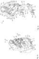
- a lifting and transport device 1 The embodiments of a lifting and transport device 1 according to the invention shown in the figures have a frame 2, a holding device 3, a lifting device 4 and first and second supports 5, 6.
- the lifting direction is designated 7 and the transport direction is designated 8.
- the frame 2 has a first and a second frame section 9, 10, which are connected to one another in an articulated manner.
- the joint axis is a pivot axis 11, about which the two frame sections 9, 10 can be pivoted relative to one another.
- the pivot axis 11 extends in the transport direction 8.
- the term “flange 12” here is understood to mean a flange connection or pairing with an upper flange 12a and a lower flange 12b.
- the flange 12 can be designed to be straight or annular in the form of an inner or outer ring.
- Each frame section 9, 10 is made up of two frame parts 13, 14; 15, 16 are formed, which are arranged in the transport direction 8 in front of and behind a load space 17, which is designed to accommodate a screwing tool 18.
- the two frame parts 13, 14 of the first frame section 9 are elongated and designed to extend perpendicular to the transport direction 8 from the flange top 19 along the flange face 20 to below the flange bottom 21. They are connected to one another in a deformation-resistant manner by two crossbars 22, 23 running in the transport direction 8, the crossbars 22, 23 being attached to the frame parts 13, 14 in a displaceable manner in the longitudinal direction of the frame parts 13, 14.
- longitudinal slots 24 are formed in the frame parts 13, 14, in which the crossbars 22, 23 are mounted.
- the cross bars 22, 23 can be fixed in their desired position in the longitudinal slots 24.
- the first support 5 is attached to a first crossbar 22. It is formed from two support rollers 5a, which are at a distance from one another in the transport direction 8 and rest on the top of the flange 19 when the lifting and transport device 1 is mounted on a flange 12. In the exemplary embodiment shown, the support rollers 5a are designed to rest on a horizontal surface section 26 of the flange top 19 and to roll on it in the transport direction 8.
- the second support 6 is attached to the second crossbar 23. It is also formed from two support rollers 6a, which are at a distance from one another in the transport direction 8. When the lifting and transport device 1 is mounted on a flange 12, the support rollers 6a rest on the underside 21 of the flange. In the exemplary embodiment shown, these support rollers 6a are also designed to rest on a horizontal surface section 27 of the underside of the flange 21 and to roll on it in the transport direction 8.
- the horizontal surface sections 26, 27 are arranged between the screw connection 28 and the flange outer edge 29.
- the support rollers 5a, 6a can be brought into contact with the flange top 19 or bottom 21 by moving the crossbars 22, 23 and the contact pressure of the support rollers 5a, 6a can also be adjusted.
- the longitudinal axis 30 of a screwing tool 18 held in the second frame section 10 - if this longitudinal axis 30 runs parallel to the longitudinal axis 31 of the screw connection 28, but not in this longitudinal axis 31 - in the form of a parallel displacement in the longitudinal axis 31 of the Screw connection 28 can be moved.
- crossbars 22, 23 can be displaced transversely to the longitudinal direction of the frame parts 13, 14 and transversely to the transport direction 8, that is to say they can be displaced horizontally to the transport direction 8 when the lifting and transport device 1 is mounted on a flange 12.
- the second frame section 10 is attached in an articulated manner to the upper end 32, 33 of the frame parts 13, 14 of the first frame section 9.
- Each frame part 15, 16 of the second frame section 10 is attached to a frame part 13, 14 of the first frame section 9 so that it can pivot about the pivot axis 11.
- the two frame parts 15, 16 of the second frame section 10 each have approximately the shape of an upside-down F, each with a longitudinal web 34 and two transverse legs 35, 36 which are rigidly connected to this and run transversely to it.
- the first transverse legs 35 arranged between the two ends 37, 38 of the longitudinal web 34 each form, with their free end 39, the articulated connection 40 with a frame part 13, 14 of the first frame section 9, the two articulated connections 40 lying on the pivot axis 11.
- the second transverse legs 36 are each arranged at the end 38 of the longitudinal web 34, which faces the first frame section 9.
- the end region 41 of the second transverse legs 36 is curved near their free end 42, with the pivot axis 11 forming the axis of curvature or the articulation points of the articulation connections 40 between the first and second frame sections 9, 10 forming the centers of curvature.
- bores 44 are formed in both curved end regions 41, each of which interacts with a locking bolt 45 in the two frame parts 13, 14 of the first frame section 9 in order to lock the second frame section 10 at a desired pivoting angle to the first frame section 9.
- this pivot angle is 0°.
- the two frame parts 15, 16 of the second frame section 10 are connected to one another in a deformation-resistant manner by three crossbars 46 running in the transport direction 8.
- the ends 37, 38 of the two longitudinal webs 34 and the free ends 42 of the second transverse legs 36 are connected to one another by crossbars 46.
- the cross bars 46 running between the longitudinal webs 34 are shaped accordingly to accommodate the screwing tool 18, in the present case bulged towards the side facing away from the cross legs 35, 36.
- the lifting device 4 is attached to the longitudinal webs 34.
- it has a gas pressure spring 47 on each longitudinal web 34, the first end 48 of which is fastened immovably near the second transverse leg 36 and the second end 49 of which is each connected to a holding element 50, which is longitudinally displaceable in a longitudinal slot 51 formed in the longitudinal web 34 is stored and the two together form the holding device 3 for holding a screwing tool 18.
- the gas pressure springs 47 With the help of the gas pressure springs 47, the screwing tool 18 is pushed upwards against gravity after tightening/loosening the screw connection 28.
- the screwing tool 18 is connected to the holding elements 50 in a non-displaceable and non-rotatable manner, i.e. also pivot-proof.
- the holding elements 50 can be screwed to the holding elements 50 or held by them magnetically or positively (e.g. by means of locking bolts).
- the holding elements 50 are in turn guided in the longitudinal slots 51 in a pivot-proof manner relative to the second frame section 10, so that when the second frame section 10 is pivoted relative to the first frame section 9, the screwing tool 18 is pivoted by the same angle relative to the first frame section 9.
- the guide bolts 52 are attached to the crossbars 22, 23 near the support rollers 5a, 6a of the first and second supports 5, 6.
- the guide bolts 52 are directed downwards to engage in an upwardly open guide groove 53 on the flange top 19.
- the guide bolts 52 are directed upwards for engagement in a downwardly open guide groove 53 on the underside of the flange 21.
- the guide grooves 53 can, for example, be incorporated directly into the flange top 19 and into the flange bottom 21, with the support rollers 5a, 6a as in the embodiment according to Figures 1a and 1b rest directly on the flange top 19 or bottom 21.
- the guide grooves 53 can also z. B. be formed in guide rails 54, which are temporarily attached to the flange top 19 and to the flange bottom 21 for assembling the screw connections 28.
- the support rollers 5a, 6a no longer rest directly on the top side 19 or bottom side 21 of the flange, but on the guide rails 54.
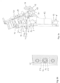
- FIG 2c is the lifting and transport device 1 from the Figures 2a and 2b shown with a held screwing tool 18 in the screwing position for tightening a screw connection 28.
- the frame parts 13, 14 of the first frame section 9 run vertically along the end face 20 of the flange 12.
- the second frame section 10 is pivoted relative to the frame parts 13, 14 of the first frame section 9 by the angle by which the top of the flange 19 is inclined relative to the horizontal is so that the longitudinal axis 30 of the screwing tool 18 coincides with the longitudinal axis 31 of the screw connection 28.
- Figure 2c shows a support sleeve 55, which is a component of the lower part of the screwing tool, rests on the top 19 of the inclined flange 12, encloses the nut 56 of the screw connection 28 to be tightened or loosened and on which the screwing tool 18 rests relative to the screw connection 28 when tightening/loosening Flange 12 is supported on the flange top 19.
- the non-hatched areas 57 result from the fact that the in Figure 2c Flange cutout shown is the cutout of an annular flange and, due to its annular curvature, a flat cut runs through the support sleeve 55 above the top of the flange 19 until it intersects the flange 12 again.
- the ones in the Figures 1a and 1b and 2a to 2d illustrated embodiments can be used for tightening or loosening screw connections 28 from the flange underside 21 by rotating about a horizontal axis so that the second frame section 10 with the held screwing tool 18 is arranged under the flange underside 21 .
- the former first support then becomes the second support 6, since it now rests on the underside of the flange 21, and the former second support becomes the first support 5, since it now rests on the top of the flange 19.
- the gas pressure springs 47 then become gas tension springs, which pull the screwing tool 18 upwards against gravity for tightening/loosening a screw connection.
- the second support 6 is attached to the second frame section 10 and is designed to rest against a component wall 58 rising from the inclined flange 12.
- the second support 6 is also formed here from two support rollers 6a; they are each attached to a longitudinal web 34 of a frame part 15, 16, namely at the end 38, at which the second cross leg 36 is also arranged.
- the support rollers 6a are mounted there in a displaceable or pivotable manner so that their position can be adapted to different pivot angles of the second frame section 6 and/or to the inclination of the component wall 58 relative to the vertical.
- the first supports 5 are also on the frame parts 13, 14 of the first frame section 9 in the same way as in the exemplary embodiments according to Figures 1a and 1b and 2a to 2d attached, with the frame parts 13, 14 only as far along the end face 20 of the Flange 12 extend, as is required for the displaceable attachment of the first support 5.
- the frame parts 13, 14 of the first frame section 9 are designed to extend along the flange end face 20 .
- the frame parts 13, 14 then each have a longitudinal slot which extends along the entire height of the flange end face 20, so that the first support 5 can be moved to such an extent that it also rests on the flange top side 19 when the lifting - and transport device 1 is rotated by 180 ° about a horizontal axis so that the second frame section 10 with the held screwing tool 18 is arranged under the flange 12 in order to tighten or loosen a screw connection 28 from the flange underside 21.
- the second support 6 is designed as a U-shaped element 59, which is designed to engage over the two screw connections lying on both sides of the screw connection 28 to be tightened or loosened.
Landscapes
- Engineering & Computer Science (AREA)
- Mechanical Engineering (AREA)
- Structural Engineering (AREA)
- Life Sciences & Earth Sciences (AREA)
- Geology (AREA)
- Transportation (AREA)
- Civil Engineering (AREA)
- Handcart (AREA)
- Load-Engaging Elements For Cranes (AREA)
- Escalators And Moving Walkways (AREA)
Applications Claiming Priority (1)
| Application Number | Priority Date | Filing Date | Title |
|---|---|---|---|
| DE102022105559.0A DE102022105559B3 (de) | 2022-03-09 | 2022-03-09 | Hebe-und Transportvorrichtung |
Publications (2)
| Publication Number | Publication Date |
|---|---|
| EP4245457A1 true EP4245457A1 (fr) | 2023-09-20 |
| EP4245457B1 EP4245457B1 (fr) | 2024-08-21 |
Family
ID=85285420
Family Applications (1)
| Application Number | Title | Priority Date | Filing Date |
|---|---|---|---|
| EP23158789.0A Active EP4245457B1 (fr) | 2022-03-09 | 2023-02-27 | Dispositif de levage et de transport |
Country Status (5)
| Country | Link |
|---|---|
| US (1) | US11731223B1 (fr) |
| EP (1) | EP4245457B1 (fr) |
| DE (1) | DE102022105559B3 (fr) |
| DK (1) | DK4245457T3 (fr) |
| ES (1) | ES2991877T3 (fr) |
Families Citing this family (1)
| Publication number | Priority date | Publication date | Assignee | Title |
|---|---|---|---|---|
| DE102023119208B3 (de) | 2023-07-20 | 2025-01-02 | Frank Hohmann | Hebe- und Transportvorrichtung |
Citations (5)
| Publication number | Priority date | Publication date | Assignee | Title |
|---|---|---|---|---|
| JPH08122479A (ja) * | 1994-10-27 | 1996-05-17 | Toshiba Corp | 原子炉格納容器上蓋のフランジボルト締付け方法とその装置 |
| KR20130026039A (ko) * | 2011-09-05 | 2013-03-13 | 삼성중공업 주식회사 | 풍력 발전기의 유지보수 로봇 |
| EP2660182A2 (fr) * | 2012-05-02 | 2013-11-06 | Hohmann, Jörg | Dispositif de levage et de transport |
| DE102019200042B3 (de) | 2019-01-04 | 2020-03-05 | Frank Hohmann | Hebe- und Transportvorrichtung |
| EP3663034A1 (fr) * | 2018-12-07 | 2020-06-10 | Hohmann, Frank | Procédé de serrage de raccords à vis |
Family Cites Families (5)
| Publication number | Priority date | Publication date | Assignee | Title |
|---|---|---|---|---|
| US4213727A (en) * | 1978-12-11 | 1980-07-22 | Morse Manufacturing Company, Inc. | Drum handling apparatus |
| US5379814A (en) * | 1993-10-07 | 1995-01-10 | Posly; Louis M. | Water bottle lifting mechanism |
| US5406996A (en) * | 1994-02-17 | 1995-04-18 | Wagner; Larry L. | Bottled water lifting apparatus |
| US5425614A (en) * | 1994-11-16 | 1995-06-20 | Perussi; Rolando | Bottle lifting and inverting apparatus |
| WO2016193297A1 (fr) | 2015-06-01 | 2016-12-08 | Total Wind A/S | Robot et outil de travail pour effectuer des opérations d'assemblage et de maintenance dans une tour à sections |
-
2022
- 2022-03-09 DE DE102022105559.0A patent/DE102022105559B3/de active Active
-
2023
- 2023-02-21 US US18/112,042 patent/US11731223B1/en active Active
- 2023-02-27 EP EP23158789.0A patent/EP4245457B1/fr active Active
- 2023-02-27 ES ES23158789T patent/ES2991877T3/es active Active
- 2023-02-27 DK DK23158789.0T patent/DK4245457T3/da active
Patent Citations (7)
| Publication number | Priority date | Publication date | Assignee | Title |
|---|---|---|---|---|
| JPH08122479A (ja) * | 1994-10-27 | 1996-05-17 | Toshiba Corp | 原子炉格納容器上蓋のフランジボルト締付け方法とその装置 |
| KR20130026039A (ko) * | 2011-09-05 | 2013-03-13 | 삼성중공업 주식회사 | 풍력 발전기의 유지보수 로봇 |
| EP2660182A2 (fr) * | 2012-05-02 | 2013-11-06 | Hohmann, Jörg | Dispositif de levage et de transport |
| DE102012009255A1 (de) | 2012-05-02 | 2013-11-07 | Jörg Hohmann | Hebe- und Transportvorrichtung |
| EP3663034A1 (fr) * | 2018-12-07 | 2020-06-10 | Hohmann, Frank | Procédé de serrage de raccords à vis |
| DE102019200042B3 (de) | 2019-01-04 | 2020-03-05 | Frank Hohmann | Hebe- und Transportvorrichtung |
| EP3677537A1 (fr) * | 2019-01-04 | 2020-07-08 | Jörg Hohmann | Dispositif de levage et de transport |
Also Published As
| Publication number | Publication date |
|---|---|
| DK4245457T3 (da) | 2024-11-18 |
| US20230286087A1 (en) | 2023-09-14 |
| DE102022105559B3 (de) | 2023-03-16 |
| ES2991877T3 (es) | 2024-12-05 |
| EP4245457B1 (fr) | 2024-08-21 |
| US11731223B1 (en) | 2023-08-22 |
Similar Documents
| Publication | Publication Date | Title |
|---|---|---|
| EP0836981B1 (fr) | Dispositif de réglage de la longueur et de l'inclinaison d'une colonne de direction pour véhicules à moteur | |
| EP0445591B1 (fr) | Dispositif d'accouplement pour une colonne de direction d'un véhicule automobile avec la queue de l'arbre d'un mécanisme de direction | |
| EP2520877B1 (fr) | Dispositif de serrage pour module PV | |
| EP3677537B1 (fr) | Dispositif de levage et de transport | |
| DE3800052A1 (de) | Positionierungsschraube | |
| DE2521426A1 (de) | Sollbruchvorrichtung zur halterung eines pfostens | |
| EP0681943A1 (fr) | Dispositif de fixation | |
| EP3053684A1 (fr) | Dispositif de separation d'une piece usinee cylindrique | |
| EP1544379B1 (fr) | Dispositif de serrage | |
| EP4245457B1 (fr) | Dispositif de levage et de transport | |
| DE2402054C2 (de) | Vorrichtung zum Festspannen von Werkstücken auf einer Aufspannplatte | |
| DE4433731A1 (de) | Schraubvorrichtung | |
| EP0245704B1 (fr) | Etai d'acier réglable en hauteur pour des coffrages de plafond et similaires | |
| DE3248937T1 (de) | Halterungs- und Abstützvorrichtung | |
| DE29800079U1 (de) | Auf der Felge eines Kraftfahrzeugrades verspannbarer Notlaufeinsatz | |
| DE3334618A1 (de) | Hydraulischer schraubenschluessel mit rolle | |
| DE102023119208B3 (de) | Hebe- und Transportvorrichtung | |
| DE102018203080B4 (de) | Fundamentsystem für die lagerung von flächig nebeneinander angeordneten solarpaneelen | |
| EP3246202B1 (fr) | Point d'ancrage | |
| EP0611711B1 (fr) | Transporteur et pièce de raccord destinée à être utilisée pour un tel transporteur | |
| DE2815845A1 (de) | Vorrichtung zum leichteren loesen festsitzender radschrauben und -muttern | |
| DE4034141C1 (en) | Guide for continuous steel casting - comprises supporting segments with rollers clamped by nuts and bolts to one-piece curved supporting frame | |
| DE102019128638A1 (de) | Vorrichtung zum verbinden eines ersten feststehenden mastteils mit einem gegenüber diesem klappbaren zweiten mastteil | |
| DE3517306A1 (de) | Vorrichtung zum ausrichten nebeneinander angeordneter schalungselemente | |
| DE3243732C2 (de) | Vorrichtung zum Verspannen von Profilsegmenten eines Ausbaurahmens |
Legal Events
| Date | Code | Title | Description |
|---|---|---|---|
| PUAI | Public reference made under article 153(3) epc to a published international application that has entered the european phase |
Free format text: ORIGINAL CODE: 0009012 |
|
| STAA | Information on the status of an ep patent application or granted ep patent |
Free format text: STATUS: THE APPLICATION HAS BEEN PUBLISHED |
|
| AK | Designated contracting states |
Kind code of ref document: A1 Designated state(s): AL AT BE BG CH CY CZ DE DK EE ES FI FR GB GR HR HU IE IS IT LI LT LU LV MC ME MK MT NL NO PL PT RO RS SE SI SK SM TR |
|
| STAA | Information on the status of an ep patent application or granted ep patent |
Free format text: STATUS: REQUEST FOR EXAMINATION WAS MADE |
|
| 17P | Request for examination filed |
Effective date: 20230928 |
|
| RBV | Designated contracting states (corrected) |
Designated state(s): AL AT BE BG CH CY CZ DE DK EE ES FI FR GB GR HR HU IE IS IT LI LT LU LV MC ME MK MT NL NO PL PT RO RS SE SI SK SM TR |
|
| GRAP | Despatch of communication of intention to grant a patent |
Free format text: ORIGINAL CODE: EPIDOSNIGR1 |
|
| STAA | Information on the status of an ep patent application or granted ep patent |
Free format text: STATUS: GRANT OF PATENT IS INTENDED |
|
| INTG | Intention to grant announced |
Effective date: 20240214 |
|
| GRAS | Grant fee paid |
Free format text: ORIGINAL CODE: EPIDOSNIGR3 |
|
| GRAA | (expected) grant |
Free format text: ORIGINAL CODE: 0009210 |
|
| STAA | Information on the status of an ep patent application or granted ep patent |
Free format text: STATUS: THE PATENT HAS BEEN GRANTED |
|
| AK | Designated contracting states |
Kind code of ref document: B1 Designated state(s): AL AT BE BG CH CY CZ DE DK EE ES FI FR GB GR HR HU IE IS IT LI LT LU LV MC ME MK MT NL NO PL PT RO RS SE SI SK SM TR |
|
| REG | Reference to a national code |
Ref country code: GB Ref legal event code: FG4D Free format text: NOT ENGLISH |
|
| REG | Reference to a national code |
Ref country code: CH Ref legal event code: EP |
|
| REG | Reference to a national code |
Ref country code: DE Ref legal event code: R096 Ref document number: 502023000116 Country of ref document: DE |
|
| P01 | Opt-out of the competence of the unified patent court (upc) registered |
Free format text: CASE NUMBER: APP_45248/2024 Effective date: 20240805 |
|
| REG | Reference to a national code |
Ref country code: IE Ref legal event code: FG4D Free format text: LANGUAGE OF EP DOCUMENT: GERMAN |
|
| REG | Reference to a national code |
Ref country code: DK Ref legal event code: T3 Effective date: 20241115 |
|
| REG | Reference to a national code |
Ref country code: ES Ref legal event code: FG2A Ref document number: 2991877 Country of ref document: ES Kind code of ref document: T3 Effective date: 20241205 |
|
| REG | Reference to a national code |
Ref country code: LT Ref legal event code: MG9D |
|
| REG | Reference to a national code |
Ref country code: NL Ref legal event code: MP Effective date: 20240821 |
|
| PG25 | Lapsed in a contracting state [announced via postgrant information from national office to epo] |
Ref country code: NO Free format text: LAPSE BECAUSE OF FAILURE TO SUBMIT A TRANSLATION OF THE DESCRIPTION OR TO PAY THE FEE WITHIN THE PRESCRIBED TIME-LIMIT Effective date: 20241121 |
|
| PG25 | Lapsed in a contracting state [announced via postgrant information from national office to epo] |
Ref country code: PL Free format text: LAPSE BECAUSE OF FAILURE TO SUBMIT A TRANSLATION OF THE DESCRIPTION OR TO PAY THE FEE WITHIN THE PRESCRIBED TIME-LIMIT Effective date: 20240821 Ref country code: FI Free format text: LAPSE BECAUSE OF FAILURE TO SUBMIT A TRANSLATION OF THE DESCRIPTION OR TO PAY THE FEE WITHIN THE PRESCRIBED TIME-LIMIT Effective date: 20240821 Ref country code: NL Free format text: LAPSE BECAUSE OF FAILURE TO SUBMIT A TRANSLATION OF THE DESCRIPTION OR TO PAY THE FEE WITHIN THE PRESCRIBED TIME-LIMIT Effective date: 20240821 Ref country code: GR Free format text: LAPSE BECAUSE OF FAILURE TO SUBMIT A TRANSLATION OF THE DESCRIPTION OR TO PAY THE FEE WITHIN THE PRESCRIBED TIME-LIMIT Effective date: 20241122 Ref country code: PT Free format text: LAPSE BECAUSE OF FAILURE TO SUBMIT A TRANSLATION OF THE DESCRIPTION OR TO PAY THE FEE WITHIN THE PRESCRIBED TIME-LIMIT Effective date: 20241223 |
|
| PG25 | Lapsed in a contracting state [announced via postgrant information from national office to epo] |
Ref country code: BG Free format text: LAPSE BECAUSE OF FAILURE TO SUBMIT A TRANSLATION OF THE DESCRIPTION OR TO PAY THE FEE WITHIN THE PRESCRIBED TIME-LIMIT Effective date: 20240821 |
|
| PG25 | Lapsed in a contracting state [announced via postgrant information from national office to epo] |
Ref country code: LV Free format text: LAPSE BECAUSE OF FAILURE TO SUBMIT A TRANSLATION OF THE DESCRIPTION OR TO PAY THE FEE WITHIN THE PRESCRIBED TIME-LIMIT Effective date: 20240821 |
|
| PG25 | Lapsed in a contracting state [announced via postgrant information from national office to epo] |
Ref country code: IS Free format text: LAPSE BECAUSE OF FAILURE TO SUBMIT A TRANSLATION OF THE DESCRIPTION OR TO PAY THE FEE WITHIN THE PRESCRIBED TIME-LIMIT Effective date: 20241221 |
|
| PG25 | Lapsed in a contracting state [announced via postgrant information from national office to epo] |
Ref country code: HR Free format text: LAPSE BECAUSE OF FAILURE TO SUBMIT A TRANSLATION OF THE DESCRIPTION OR TO PAY THE FEE WITHIN THE PRESCRIBED TIME-LIMIT Effective date: 20240821 |
|
| PG25 | Lapsed in a contracting state [announced via postgrant information from national office to epo] |
Ref country code: RS Free format text: LAPSE BECAUSE OF FAILURE TO SUBMIT A TRANSLATION OF THE DESCRIPTION OR TO PAY THE FEE WITHIN THE PRESCRIBED TIME-LIMIT Effective date: 20241121 |
|
| PG25 | Lapsed in a contracting state [announced via postgrant information from national office to epo] |
Ref country code: RS Free format text: LAPSE BECAUSE OF FAILURE TO SUBMIT A TRANSLATION OF THE DESCRIPTION OR TO PAY THE FEE WITHIN THE PRESCRIBED TIME-LIMIT Effective date: 20241121 Ref country code: PT Free format text: LAPSE BECAUSE OF FAILURE TO SUBMIT A TRANSLATION OF THE DESCRIPTION OR TO PAY THE FEE WITHIN THE PRESCRIBED TIME-LIMIT Effective date: 20241223 Ref country code: PL Free format text: LAPSE BECAUSE OF FAILURE TO SUBMIT A TRANSLATION OF THE DESCRIPTION OR TO PAY THE FEE WITHIN THE PRESCRIBED TIME-LIMIT Effective date: 20240821 Ref country code: NO Free format text: LAPSE BECAUSE OF FAILURE TO SUBMIT A TRANSLATION OF THE DESCRIPTION OR TO PAY THE FEE WITHIN THE PRESCRIBED TIME-LIMIT Effective date: 20241121 Ref country code: NL Free format text: LAPSE BECAUSE OF FAILURE TO SUBMIT A TRANSLATION OF THE DESCRIPTION OR TO PAY THE FEE WITHIN THE PRESCRIBED TIME-LIMIT Effective date: 20240821 Ref country code: LV Free format text: LAPSE BECAUSE OF FAILURE TO SUBMIT A TRANSLATION OF THE DESCRIPTION OR TO PAY THE FEE WITHIN THE PRESCRIBED TIME-LIMIT Effective date: 20240821 Ref country code: IS Free format text: LAPSE BECAUSE OF FAILURE TO SUBMIT A TRANSLATION OF THE DESCRIPTION OR TO PAY THE FEE WITHIN THE PRESCRIBED TIME-LIMIT Effective date: 20241221 Ref country code: HR Free format text: LAPSE BECAUSE OF FAILURE TO SUBMIT A TRANSLATION OF THE DESCRIPTION OR TO PAY THE FEE WITHIN THE PRESCRIBED TIME-LIMIT Effective date: 20240821 Ref country code: GR Free format text: LAPSE BECAUSE OF FAILURE TO SUBMIT A TRANSLATION OF THE DESCRIPTION OR TO PAY THE FEE WITHIN THE PRESCRIBED TIME-LIMIT Effective date: 20241122 Ref country code: FI Free format text: LAPSE BECAUSE OF FAILURE TO SUBMIT A TRANSLATION OF THE DESCRIPTION OR TO PAY THE FEE WITHIN THE PRESCRIBED TIME-LIMIT Effective date: 20240821 Ref country code: BG Free format text: LAPSE BECAUSE OF FAILURE TO SUBMIT A TRANSLATION OF THE DESCRIPTION OR TO PAY THE FEE WITHIN THE PRESCRIBED TIME-LIMIT Effective date: 20240821 |
|
| PG25 | Lapsed in a contracting state [announced via postgrant information from national office to epo] |
Ref country code: RO Free format text: LAPSE BECAUSE OF FAILURE TO SUBMIT A TRANSLATION OF THE DESCRIPTION OR TO PAY THE FEE WITHIN THE PRESCRIBED TIME-LIMIT Effective date: 20240821 Ref country code: SM Free format text: LAPSE BECAUSE OF FAILURE TO SUBMIT A TRANSLATION OF THE DESCRIPTION OR TO PAY THE FEE WITHIN THE PRESCRIBED TIME-LIMIT Effective date: 20240821 |
|
| PG25 | Lapsed in a contracting state [announced via postgrant information from national office to epo] |
Ref country code: EE Free format text: LAPSE BECAUSE OF FAILURE TO SUBMIT A TRANSLATION OF THE DESCRIPTION OR TO PAY THE FEE WITHIN THE PRESCRIBED TIME-LIMIT Effective date: 20240821 |
|
| PG25 | Lapsed in a contracting state [announced via postgrant information from national office to epo] |
Ref country code: CZ Free format text: LAPSE BECAUSE OF FAILURE TO SUBMIT A TRANSLATION OF THE DESCRIPTION OR TO PAY THE FEE WITHIN THE PRESCRIBED TIME-LIMIT Effective date: 20240821 |
|
| PG25 | Lapsed in a contracting state [announced via postgrant information from national office to epo] |
Ref country code: SK Free format text: LAPSE BECAUSE OF FAILURE TO SUBMIT A TRANSLATION OF THE DESCRIPTION OR TO PAY THE FEE WITHIN THE PRESCRIBED TIME-LIMIT Effective date: 20240821 Ref country code: IT Free format text: LAPSE BECAUSE OF FAILURE TO SUBMIT A TRANSLATION OF THE DESCRIPTION OR TO PAY THE FEE WITHIN THE PRESCRIBED TIME-LIMIT Effective date: 20240821 |
|
| REG | Reference to a national code |
Ref country code: DE Ref legal event code: R097 Ref document number: 502023000116 Country of ref document: DE |
|
| PLBE | No opposition filed within time limit |
Free format text: ORIGINAL CODE: 0009261 |
|
| STAA | Information on the status of an ep patent application or granted ep patent |
Free format text: STATUS: NO OPPOSITION FILED WITHIN TIME LIMIT |
|
| PGFP | Annual fee paid to national office [announced via postgrant information from national office to epo] |
Ref country code: ES Payment date: 20250331 Year of fee payment: 3 |
|
| 26N | No opposition filed |
Effective date: 20250522 |
|
| PG25 | Lapsed in a contracting state [announced via postgrant information from national office to epo] |
Ref country code: SE Free format text: LAPSE BECAUSE OF FAILURE TO SUBMIT A TRANSLATION OF THE DESCRIPTION OR TO PAY THE FEE WITHIN THE PRESCRIBED TIME-LIMIT Effective date: 20240821 |
|
| PG25 | Lapsed in a contracting state [announced via postgrant information from national office to epo] |
Ref country code: MC Free format text: LAPSE BECAUSE OF FAILURE TO SUBMIT A TRANSLATION OF THE DESCRIPTION OR TO PAY THE FEE WITHIN THE PRESCRIBED TIME-LIMIT Effective date: 20240821 |
|
| PG25 | Lapsed in a contracting state [announced via postgrant information from national office to epo] |
Ref country code: LU Free format text: LAPSE BECAUSE OF NON-PAYMENT OF DUE FEES Effective date: 20250227 |
|
| REG | Reference to a national code |
Ref country code: BE Ref legal event code: MM Effective date: 20250228 |
|
| REG | Reference to a national code |
Ref country code: DE Ref legal event code: R082 Ref document number: 502023000116 Country of ref document: DE Representative=s name: ALPSPITZ IP ALLGAYER UND PARTNER PATENTANWAELT, DE |
|
| PG25 | Lapsed in a contracting state [announced via postgrant information from national office to epo] |
Ref country code: FR Free format text: LAPSE BECAUSE OF NON-PAYMENT OF DUE FEES Effective date: 20250228 |
|
| PG25 | Lapsed in a contracting state [announced via postgrant information from national office to epo] |
Ref country code: BE Free format text: LAPSE BECAUSE OF NON-PAYMENT OF DUE FEES Effective date: 20250228 |
|
| PG25 | Lapsed in a contracting state [announced via postgrant information from national office to epo] |
Ref country code: IE Free format text: LAPSE BECAUSE OF NON-PAYMENT OF DUE FEES Effective date: 20250227 |
|
| PGFP | Annual fee paid to national office [announced via postgrant information from national office to epo] |
Ref country code: DK Payment date: 20260220 Year of fee payment: 4 Ref country code: DE Payment date: 20260218 Year of fee payment: 4 |
|
| PGFP | Annual fee paid to national office [announced via postgrant information from national office to epo] |
Ref country code: AT Payment date: 20260301 Year of fee payment: 4 |