EP4246043A1 - Ensemble brûleur à gaz, appareil de chauffage à gaz et utilisation - Google Patents
Ensemble brûleur à gaz, appareil de chauffage à gaz et utilisation Download PDFInfo
- Publication number
- EP4246043A1 EP4246043A1 EP23161656.6A EP23161656A EP4246043A1 EP 4246043 A1 EP4246043 A1 EP 4246043A1 EP 23161656 A EP23161656 A EP 23161656A EP 4246043 A1 EP4246043 A1 EP 4246043A1
- Authority
- EP
- European Patent Office
- Prior art keywords
- gas
- burner
- gas burner
- flame arrester
- flame
- Prior art date
- Legal status (The legal status is an assumption and is not a legal conclusion. Google has not performed a legal analysis and makes no representation as to the accuracy of the status listed.)
- Granted
Links
Images

Classifications
-
- F—MECHANICAL ENGINEERING; LIGHTING; HEATING; WEAPONS; BLASTING
- F23—COMBUSTION APPARATUS; COMBUSTION PROCESSES
- F23D—BURNERS
- F23D14/00—Burners for combustion of a gas, e.g. of a gas stored under pressure as a liquid
- F23D14/46—Details
- F23D14/72—Safety devices, e.g. operative in case of failure of gas supply
- F23D14/82—Preventing flashback or blowback
-
- F—MECHANICAL ENGINEERING; LIGHTING; HEATING; WEAPONS; BLASTING
- F23—COMBUSTION APPARATUS; COMBUSTION PROCESSES
- F23D—BURNERS
- F23D2209/00—Safety arrangements
- F23D2209/10—Flame flashback
Definitions
- the invention relates to a gas burner arrangement, a gas heater and a use of a gas burner arrangement.
- Gas burners for condensing boilers often consist of perforated sheets, which can be flat, curved or designed as a cylinder.
- a fuel gas-air mixture provided for the gas burner flows from the back through the holes in the sheet and is ignited and burned on the front.
- the fuel gas e.g. propane, methane, hydrogen or mixtures thereof
- different flame speeds result during combustion. If the flame speed is higher than the outflow speed of the fuel gas-air mixture from the burner holes, a so-called flame flashback can occur into the gas-air mixture path in front of the burner. Such a flashback can also occur if the perforated plate temperature on the back is higher than the ignition temperature of the gas-air mixture used.
- the gas-air mixture then unintentionally burns in front of the burner or in the upstream fuel gas-air mixture path.
- the consequences can be a pressure surge triggered by combustion and/or a high thermal load on components in the fuel gas-air mixture path and/or other inlets.
- a (plastic) impeller of a blower in the air supply can thermally deform or be damaged by a pressure surge.
- At least one flame arrester can be provided between the air supply and the burner, which extends over a line cross-section of the fuel gas-air mixture path, the air supply or the fuel gas supply.
- the flame arrester can extend over the entire flow cross section of the fuel gas-air mixture path and in particular cannot allow any bypass flow.
- the flame arrester can be made of a high-temperature-resistant material, such as a metal, a ceramic or mixtures thereof.
- the flame arrester can be (permanently) fixed in or between housing sections of the fuel gas-air mixture path and/or the gas burner.
- the flame arrester In addition to the mechanical and thermal stability of the flame arrester and its function of stopping or even (at least partially) extinguishing an impinging flame front, there are other requirements. This includes, for example, that the flame arrester has the lowest possible tendency to get dirty and/or has a high level of self-cleaning ability during operation, because dust is often introduced via the fuel gas-air mixture (or the mixed air in the environment). Such contamination can lead to a significant increase in pressure loss, which can lead to a loss of performance of the gas heater.
- a gas heater must be created in which mechanical and/or thermal loads due to flashbacks can be reduced or avoided.
- a (plastic) impeller of a blower in the air supply should be protected from high thermal load and/or a large pressure surge due to a flashback.
- a gas burner arrangement contributes to this, which includes at least one flame arrester, which is formed with an inlet along an axis and an outlet obliquely to this axis.
- the at least one flame arrester can be inserted into a burner chamber of a gas burner of a gas heater.
- the flame arrester and gas burner are designed in such a way that a surface load during operation is in the range of 1.5 to 7.0 W/mm 2 , in particular in the range of 1.5 to 3.0 W/mm 2 [watts per square millimeter].
- the gas burner arrangement can in particular be designed in the manner of a coordinated set of flame arrester and gas burner.
- the gas burner is designed with an internal burner chamber in which the flame arrester can be accommodated.
- the burner space is at least partially delimited by a burner wall, the burner wall having a plurality of grouped or evenly distributed openings can.
- the gas burner can be designed with a substantially round or rectangular cross section (perpendicular to the axis).
- the burner wall is preferably formed with a steel sheet.
- the fuel gas-air mixture can be supplied to the gas burner or the flame arrester via an inlet.
- the fuel gas-air mixture can flow in via the inlet essentially along a central axis of the gas burner or the burner chamber.
- a change in direction of the gas flow can be generated in the gas burner or burner chamber, so that the fuel gas-air mixture then leaves the burner chamber via the burner wall obliquely, in particular at an angle greater than 0° to the axis and preferably substantially perpendicular to the axis.
- the fuel gas-air mixture flows through the flame arrester and the burner wall, which is provided with a large number of openings, then ignites and therefore forms a flame front outside the gas burner.
- the flame arrester is spaced or protected from the (regular) flame front by the burner wall and/or the flame arrester is arranged on a side/surface of the burner wall facing away from the flame front.
- the flame arrester can be adapted to the gas burner in such a way that its outlet spans the outlet of the burner wall, in particular at least extensively or even completely covers the outlet.
- the flame arrester can be designed as a single layer (possibly with several layers of metal and/or ceramic lying on top of each other), which encloses or delimits a partial volume of the burner chamber.
- the flame arrester can flow through in the area of the outlet for the fuel gas air mixture, which is in particular designed so that it can flow through (approximately or exactly) with the same flow direction as the outlet of the gas burner.
- the flame arrester prefferably be designed in such a way that it can be mounted on the gas burner in the area of the inlet and, when mounted, extends (far) into the burner chamber, e.g. B. also coaxial.
- the extent of the flame arrester into the gas burner can be at least 50% the axial length of the burner chamber, preferably at least 80%.
- the surface area of the flame barrier should be as large as possible in order to achieve low pressure losses with and without dust contamination.
- the surface load is preferably adapted to the extent of the flame barrier, e.g. B.
- a surface load during operation in the range of 3.0 to 7.0 W/mm 2 is maintained at an extent of over 50% to 80% of the axial length of the burner chamber or a surface load during operation in the range of 1.5 to 3 .0 W/mm 2 is maintained over 80% of the axial length of the burner chamber.
- a flame arrester can also be used in so-called flat burners, which are operated in particular with hydrogen.
- the flame arrester is designed, for example, as a parallel plane to the burner surface.
- the other parameters and features can be transferred accordingly.
- a gas burner arrangement can be provided here, comprising at least one flat flame arrester, wherein the at least one flat flame arrester can be used in a burner chamber of a gas burner of a gas heater, and wherein the flame arrester and gas burner are designed in such a way that a surface load during operation is in the range of 1.5 up to 7.0 W/mm 2 .
- the flame arrester can be arranged one behind the other or along the flow direction between the inlet and the burner surface.
- the flame arrester is designed in particular so that the (maximum) surface load during operation of the gas burner is in the range of 1.5 or 1.8 to 3.0 W/mm 2 , preferably in the range of 2.0 to 2.6 W / mm2 .
- the area load can be referred to as the specific area load.
- the surface load can be determined from the quotient of the heating output of the gas burner and the active surface of the flame arrester (in particular comprising the outlet) (the fuel gas air mixture flows through it). The expert knows the heating output of the gas heater or the gas burner, so that he can then easily design the flame arrester.
- the maximum or nominal output is in the range from 10 kW [kilowatt] to 200 kW, e.g. B.
- the flame arrester is particularly effective with a low pressure loss at the same time. This can result in particularly intensive protection of the fan because, on the one hand, the effectiveness of the flame arrester reliably stops pressure surges and temperature fronts, and on the other hand, very low fan outputs are required in regular operation due to the low pressure loss.
- the at least one flame barrier can have a porosity (in the area of the outlet) greater than 15%, in particular at least 35% and particularly preferably at most 50%.
- the porosity can be determined from the quotient of the sum of all freely flowable areas (pores) and the entire active surface of the flame arrester (particularly in the area of the outlet). It is possible for the gas burner or the (adjacent) burner wall (at least in sections) to be designed with a significantly smaller porosity, for example by a factor of at least 2, in particular a factor of at least 5 or even at least 10.
- Flame arresters increase the free flow area in order to reduce the pressure loss and at the same time the tendency to contamination for a given extinguishing distance (of the flame), e.g. less than 0.27 mm for hydrogen.
- the porosity relates in particular to a volume porosity of the flame barrier.
- the expansion of the freely flowable areas (pores) in the direction of the wall thickness of the flame barrier are also taken into account. It is possible that the flame barrier is not made flat (made of a layer of material), but rather z. B. as a (thick-walled) body made of sintered powder or a multi-layer composite made of expanded metal and/or nonwoven material. A comparatively high porosity is advantageous for low pressure losses, which is also the case Wall thickness of the flame arrester must be taken into account.
- Sintered powder fills can be used as flame barriers as thick-walled components, e.g. B.
- Multi-layer sintered expanded metals can be made comparatively thin (e.g. with a wall thickness in the range of up to a maximum of 1 mm), which means that a lower volume porosity also leads to low pressure losses.
- Fleeces and open-pored foams can also be used to build thick-walled flame arresters (e.g. with a wall thickness in the region of greater than 1 mm), and can also advantageously have high porosities.
- the following preferred volume porosities are suggested: sintered powder bed in the range of 26 - 48% by volume; Expanded metal (multi-layer) in the range of 35 - 50% by volume; Fleece in the range above 65% by volume; open-pored foam in the range of 70 - 98 vol.%.
- the outlet of the flame arrester can be arranged (or arranged) perpendicular to the axis at a distance from a burner wall of the gas burner, in particular at a distance greater than 1 millimeter. This applies in particular if the flame arrester and burner wall are flowed through by the fuel gas air mixture in the same (particularly radial) flow direction. This means in particular that the outlet of the flame arrester is away from the axis, i.e. the fuel gas air mixture within the flame arrester is deflected from the central flow parallel to the axis towards the distant outlet.
- the exit can be formed by means of a large number of (micro) openings, (micro) slots or pores.
- the outlet can be formed coaxially to the axis in a sleeve-like section of the flame arrester.
- the redirection of the fuel gas-air mixture can be formed, for example, by means of a closure element (the flame arrester) that cannot be flowed through, which spans the axis and is opposite the inlet.
- a distance from the outlet of the flame arrester and a burner wall of the gas burner in the range of 3 to 20 mm [millimeters], in particular in the range of 5 to 10 mm. It is particularly preferred that a selected distance is essentially constant over the entire exit. It is possible that the distance increases and/or decreases; in particular, there may be a (slightly) conical envelope volume between the outlet of the flame arrester and the burner wall of the gas burner. The distance between the exit of the flame arrester and the outlet of the gas burner or the section of the burner wall through which flow can flow must be determined in the direction of flow of the gas.
- the flame arrester does not rest directly on the back of the burner wall, but that a preferably uniform gap with a predetermined distance is initially provided there.
- the distance is designed in particular so that in the event of a flame flashback, the flame front can spread into the gap and thus cover the surface of the flame surface over a larger area.
- the specified upper limit of the distance is useful in order to limit the ignitable volume of fuel gas-air mixture in the fuel gas-air mixture path. This reduces the noise and/or the pressure wave of the flashback.
- the upper limit of the distance can also be chosen to be adapted to the structure or load limit of the layers of the flame arrester.
- a further advantage of this distance is that the heat input into the flame arrester can be adjusted or limited during normal operation of the gas heater, which benefits the long-term consistent functionality of the flame arrester. If the distance between the (hot) burner body and the flame arrester is too small, there is also the risk that the flame arrester will heat up to such an extent that the ignition temperature of the gas-air mixture will be reached and unwanted ignition will occur. Even if the ignition temperature is not reached, if the flame arrester is too hot, the heat dissipation decreases, so that the extinguishing effect is negatively affected.
- the distance or the selected distance dimension is important because this reduces the surface load on the flame arrester.
- the hot gas flowing back through the burner surface is distributed over a larger area in the gap, which means that the heat or energy to be absorbed is also distributed over a larger area.
- the flow speed is reduced and the residence time is increased, which promotes flame extinguishing.
- a combustion volume can be provided in the burner chamber, which lies between the at least one flame arrester and the burner wall of the gas burner and is (greater than 0) a maximum of 70%, preferably at least 40% or even only at least 22% of the burner chamber.
- the combustion volume can be described as the envelope volume between the flame arrester and the burner wall.
- the combustion volume describes in particular the area in the gas burner in which the flame recoil spreads.
- the flame arrester and the gas burner are in particular coordinated with one another in such a way that the volume between the two components is as small as possible because the fuel gas-air mixture burns in this area in the event of a flashback.
- the energy converted can be kept small. It is possible to specifically adapt or reduce the burner volume, for example through (local) deviations in the basic shape of the gas burner, installations in the gas burner or the like, without reducing the active burner area.
- a combined flow through the flame arrester and gas burner is coordinated in such a way that a Péclet number is less than 65. It is particularly preferred that there is a Péclet number of less than 15, and this limit should apply in particular when the arrangement is operated with hydrogen or a fuel gas-air mixture containing hydrogen.
- the Péclet number is a criterion familiar to those skilled in the art that can be used to determine whether or not a flame front spreads through a material or a collection of materials.
- the (modified) Péclet number is formed using the laminar burning velocity instead of a flow velocity.
- An effective pore diameter is used as the characteristic length, which, in contrast to the conventional formulation, which is formed with a length dimension equivalent to flow processes, represents a dimension equivalent to heat transport. This length measurement can be understood as the extinguishing distance of a pipe with the same mixture composition.
- the (modified) Péclet number can therefore be understood as the ratio of heat production (burning rate) and the reaction to heat dissipation through heat conduction. Further explanations, to which full reference can be made, can be found in the DE 43 22 109 A1 .
- Gas burner arrangement which comprises at least one flame arrester, which has an inlet (along an axis) and an Exit (oblique to this axis) is formed.
- the at least one flame arrester can be inserted into a burner chamber of a gas burner of a gas heater.
- a combined flow through the flame arrester and gas burner is coordinated so that a Péclet number is less than 65. If necessary, this arrangement can be the basis for all other designs of the gas burner and/or the flame arrester proposed here.
- This criterion can now be used to determine an effective pore diameter with respect to the flame barrier for a given composition of the fuel gas-air mixture, with which flame spread can be prevented.
- the Péclet number criterion was formulated for a static gas mixture in a cold porous medium, it will be applied here to porous media through which flow occurs.
- the effective pore diameter of the flame arrester is the diameter of a circular pore; if the pore has different shapes, it is a corresponding "hydraulic" diameter.
- the laminar burning speed (sometimes also called “laminar flame speed”) depends on the fuel gas-air mixture and is therefore also a function of the air ratio.
- the laminar combustion rate for fuel gas-air mixtures reaches its maximum at a stoichiometric ratio.
- a gas heater is specified with a predetermined power range, which is in the range of 10 to 200 kW, and has a gas burner arrangement of the type disclosed here.
- the features disclosed for the gas burner arrangement can also be used individually and/or in combination with one another to characterize the gas heater.
- the gas heater is in particular designed to burn hydrogen or hydrogen-containing fuel gas-air mixture.
- the gas heater can include an ignition device, a regulation and control unit, a gas delivery unit and a flame monitor.
- Fig. 1 shows the basic structure of a gas heater 8.
- This forms a fuel gas-air mixture path 18, which z. B. a mixture of a fuel gas (such as hydrogen or natural gas) and ambient air can flow through in a flow direction 10 (in regular operation), this fuel gas-air mixture path 18 opening or ending in a gas burner 7.
- the fuel gas air mixture path 18 can consist of two line connections, a line connection for fuel gas with an actuating element 17 (valve) for the metered, controlled addition of fuel gas into a stream of ambient air, which is connected to a conveyor 16 (blower) via a combustion air path 15 can be added.
- the fuel gas-air mixture or gas mixture passes through the gas burner 7 and can be ignited outside by means of an ignition device 19.
- the resulting flames 14 are normally arranged outside the gas burner 7 in a combustion chamber, whereby z. B. an external heat exchanger 13 through which heating water flows can be heated. This describes regular operation.
- a gas burner arrangement 1 with a (single) flame arrester 2 ensures that the flame front is stopped or extinguished there.
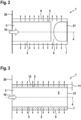
- Fig. 2 shows a (cylindrical) gas burner arrangement 1 schematically and in longitudinal section, which has a (cylindrical) flame arrester 2.
- the gas burner 7 can be designed with a flange 20, whereby the flame arrester 2 can be mounted in an aligned manner, possibly also via a collar. It can thus be provided that the burner wall 9 of the gas burner 7 and the flame arrester 2 are at least partially coaxial about a central axis 4.
- the flow direction 10 of the fuel gas-air mixture corresponds approximately to the course of the axis 4 in the area of the inlet 3.
- the flame arrester 2 (radial and circumferential) also forms a (large-area) outlet 5, which allows the fuel gas-air mixture to flow out obliquely or here vertically to this axis 4 guaranteed.
- the flame arrester 2 is inserted into the burner chamber 6 of the gas burner 7 or is completely accommodated by it. It should be noted here that the gas burner 7 has a significantly greater length in the direction of the axis 4 than the extension of the flame arrester 2 in this direction. Therefore, a closure element 21 was provided in the gas burner 7, which extends into the burner chamber 6 in order to reduce the volume between the burner wall 9 and the flame arrester 2.
- the flame arrester 2 and the gas burner 7 are designed so that a surface load during operation is in the range of 1.8 to 3.0 W/mm 2 .
- a surface load during operation is in the range of 1.8 to 3.0 W/mm 2 .
- the spatial dimensions and/or the position of the two components relative to one another can be set up or coordinated accordingly.
- Fig. 3 illustrates a further exemplary embodiment of a (cylindrical) gas burner in longitudinal section. Since the same components are provided with the same reference numbers, reference can be made in full to the explanations above.
- FIG. 2 A flat, plate-shaped closing element 21 (lid) is provided here, to which the lateral surface of the flame arrester 2 is attached.
- the flame arrester 2 is integrated, that is, the flame arrester 2 is inseparably connected to the gas burner 2.
- the cover and flange of the gas burner 2 also provide the fastening surfaces for the flame arrester 2. This means that the flame arrester 2 is formed over the entire axial length of the gas burner 2. It is further provided that these two components form a constant (small) distance 11 from one another, so that a combustion volume 12 (small) is preset.
- a flame arrester was specified whose structure can be easily, flexibly and cost-effectively adapted to various operating or environmental conditions for gas burners or gas heaters.
- a gas heater was also demonstrated in which mechanical and/or thermal loads due to flashbacks can be reduced or avoided.
Landscapes
- Engineering & Computer Science (AREA)
- Chemical & Material Sciences (AREA)
- Combustion & Propulsion (AREA)
- Mechanical Engineering (AREA)
- General Engineering & Computer Science (AREA)
- Gas Burners (AREA)
Applications Claiming Priority (1)
| Application Number | Priority Date | Filing Date | Title |
|---|---|---|---|
| DE102022106404.2A DE102022106404A1 (de) | 2022-03-18 | 2022-03-18 | Gasbrenneranordnung, Gasheizgerät und Verwendung |
Publications (3)
| Publication Number | Publication Date |
|---|---|
| EP4246043A1 true EP4246043A1 (fr) | 2023-09-20 |
| EP4246043C0 EP4246043C0 (fr) | 2025-05-21 |
| EP4246043B1 EP4246043B1 (fr) | 2025-05-21 |
Family
ID=85640771
Family Applications (1)
| Application Number | Title | Priority Date | Filing Date |
|---|---|---|---|
| EP23161656.6A Active EP4246043B1 (fr) | 2022-03-18 | 2023-03-14 | Ensemble brûleur à gaz, appareil de chauffage à gaz et utilisation |
Country Status (2)
| Country | Link |
|---|---|
| EP (1) | EP4246043B1 (fr) |
| DE (1) | DE102022106404A1 (fr) |
Families Citing this family (2)
| Publication number | Priority date | Publication date | Assignee | Title |
|---|---|---|---|---|
| DE102023129676A1 (de) * | 2023-10-27 | 2025-04-30 | Vaillant Gmbh | Heizgerät |
| DE102024204999A1 (de) * | 2024-05-29 | 2025-12-04 | Robert Bosch Gesellschaft mit beschränkter Haftung | Vorrichtung zum Verbrennen gasförmiger Brennstoffe, insbesondere Brennstoffgemische |
Citations (4)
| Publication number | Priority date | Publication date | Assignee | Title |
|---|---|---|---|---|
| WO1993018342A1 (fr) * | 1992-03-03 | 1993-09-16 | N.V. Bekaert S.A. | Plaque poreuse en fibres metalliques |
| DE4322109A1 (de) | 1993-07-02 | 1995-01-12 | Durst Franz Prof Dr Dr H C | Brenner |
| DE202013102110U1 (de) * | 2012-07-27 | 2013-10-29 | Ulrich Dreizler | Brenner mit einer Oberflächenverbrennung |
| EP3184892A1 (fr) * | 2015-12-22 | 2017-06-28 | Bosch Termotecnologia S.A. | Brûleur |
-
2022
- 2022-03-18 DE DE102022106404.2A patent/DE102022106404A1/de active Pending
-
2023
- 2023-03-14 EP EP23161656.6A patent/EP4246043B1/fr active Active
Patent Citations (4)
| Publication number | Priority date | Publication date | Assignee | Title |
|---|---|---|---|---|
| WO1993018342A1 (fr) * | 1992-03-03 | 1993-09-16 | N.V. Bekaert S.A. | Plaque poreuse en fibres metalliques |
| DE4322109A1 (de) | 1993-07-02 | 1995-01-12 | Durst Franz Prof Dr Dr H C | Brenner |
| DE202013102110U1 (de) * | 2012-07-27 | 2013-10-29 | Ulrich Dreizler | Brenner mit einer Oberflächenverbrennung |
| EP3184892A1 (fr) * | 2015-12-22 | 2017-06-28 | Bosch Termotecnologia S.A. | Brûleur |
Also Published As
| Publication number | Publication date |
|---|---|
| DE102022106404A1 (de) | 2023-09-21 |
| EP4246043C0 (fr) | 2025-05-21 |
| EP4246043B1 (fr) | 2025-05-21 |
Similar Documents
| Publication | Publication Date | Title |
|---|---|---|
| EP2467642B1 (fr) | Brûleur radiant | |
| DE4322109C2 (de) | Brenner für ein Gas/Luft-Gemisch | |
| DE102004049903B4 (de) | Brennervorrichtung mit einem Porenkörper | |
| DE4326945A1 (de) | Gaskocheinrichtung mit unter einer durchgehenden Kochfläche aus einem für Wärmestrahlung durchlässigen Material, wie Glaskeramik, angeordneten Gasstrahlungsbrennern | |
| EP4246043B1 (fr) | Ensemble brûleur à gaz, appareil de chauffage à gaz et utilisation | |
| DE102021125524A1 (de) | Flammensperre, Gasbrenner und Gasheizgerät | |
| EP2708814A1 (fr) | Brûleur radiant | |
| EP3974719A1 (fr) | Appareil de chauffage au gaz | |
| EP0718551A2 (fr) | Brûleur radiant avec une plaque de brûleur perméable au gaz | |
| EP1523641B1 (fr) | Bruleur a corps poreux et appareil de cuisson contenant au moins un bruleur a corps poreux | |
| EP1476697B1 (fr) | Emetteur infrarouge plan | |
| EP4063733B1 (fr) | Appareil de chauffage avec un dispositif permettant de réduire les conséquences d'un retour de flamme dans un brûleur à prémélange de l'appareil de chauffage | |
| WO2003069225A1 (fr) | Emetteur de rayons infrarouges sous la forme d'un emetteur plan | |
| DE69929769T2 (de) | Brennerbaueinheit und Brennerkopf zur Gasmischungsverbrennung | |
| EP1893915B1 (fr) | Systeme bruleur et son mode de fonctionnement | |
| DE19718885C2 (de) | Gasbrenner | |
| DE10160837B4 (de) | Verfahren der Mischung von heißen Brennergasen mit Sekundärluft zur Temperaturbegrenzung | |
| DE69127781T2 (de) | Brenner mit oberflächenverbrennung | |
| EP4075061B1 (fr) | Dispositif de diminution des conséquences d'un retour de flamme dans un brûleur à prémélange d'un chauffage | |
| EP0794384B1 (fr) | Petit appareil de combustion pour l'usage domestique | |
| AT299490B (de) | Brenner für flüssige und/oder gasförmige Brennstoffe | |
| DE1955357A1 (de) | Fuer fliessfaehige Brennstoffe geeigneter Brenner | |
| DE19807239C2 (de) | Einspritzventil | |
| DE19541802A1 (de) | Gasbrenner mit festkörpergestützter, flammloser Verbrennung | |
| EP1016826A2 (fr) | Brûleur à gaz et son procédé de fonctionnement |
Legal Events
| Date | Code | Title | Description |
|---|---|---|---|
| PUAI | Public reference made under article 153(3) epc to a published international application that has entered the european phase |
Free format text: ORIGINAL CODE: 0009012 |
|
| STAA | Information on the status of an ep patent application or granted ep patent |
Free format text: STATUS: THE APPLICATION HAS BEEN PUBLISHED |
|
| AK | Designated contracting states |
Kind code of ref document: A1 Designated state(s): AL AT BE BG CH CY CZ DE DK EE ES FI FR GB GR HR HU IE IS IT LI LT LU LV MC ME MK MT NL NO PL PT RO RS SE SI SK SM TR |
|
| STAA | Information on the status of an ep patent application or granted ep patent |
Free format text: STATUS: REQUEST FOR EXAMINATION WAS MADE |
|
| 17P | Request for examination filed |
Effective date: 20240314 |
|
| RBV | Designated contracting states (corrected) |
Designated state(s): AL AT BE BG CH CY CZ DE DK EE ES FI FR GB GR HR HU IE IS IT LI LT LU LV MC ME MK MT NL NO PL PT RO RS SE SI SK SM TR |
|
| GRAP | Despatch of communication of intention to grant a patent |
Free format text: ORIGINAL CODE: EPIDOSNIGR1 |
|
| STAA | Information on the status of an ep patent application or granted ep patent |
Free format text: STATUS: GRANT OF PATENT IS INTENDED |
|
| INTG | Intention to grant announced |
Effective date: 20241216 |
|
| GRAS | Grant fee paid |
Free format text: ORIGINAL CODE: EPIDOSNIGR3 |
|
| GRAA | (expected) grant |
Free format text: ORIGINAL CODE: 0009210 |
|
| STAA | Information on the status of an ep patent application or granted ep patent |
Free format text: STATUS: THE PATENT HAS BEEN GRANTED |
|
| AK | Designated contracting states |
Kind code of ref document: B1 Designated state(s): AL AT BE BG CH CY CZ DE DK EE ES FI FR GB GR HR HU IE IS IT LI LT LU LV MC ME MK MT NL NO PL PT RO RS SE SI SK SM TR |
|
| REG | Reference to a national code |
Ref country code: GB Ref legal event code: FG4D Free format text: NOT ENGLISH |
|
| REG | Reference to a national code |
Ref country code: CH Ref legal event code: EP |
|
| REG | Reference to a national code |
Ref country code: DE Ref legal event code: R096 Ref document number: 502023001013 Country of ref document: DE |
|
| REG | Reference to a national code |
Ref country code: IE Ref legal event code: FG4D Free format text: LANGUAGE OF EP DOCUMENT: GERMAN |
|
| U01 | Request for unitary effect filed |
Effective date: 20250605 |
|
| U07 | Unitary effect registered |
Designated state(s): AT BE BG DE DK EE FI FR IT LT LU LV MT NL PT RO SE SI Effective date: 20250612 |
|
| PG25 | Lapsed in a contracting state [announced via postgrant information from national office to epo] |
Ref country code: ES Free format text: LAPSE BECAUSE OF FAILURE TO SUBMIT A TRANSLATION OF THE DESCRIPTION OR TO PAY THE FEE WITHIN THE PRESCRIBED TIME-LIMIT Effective date: 20250521 |
|
| PG25 | Lapsed in a contracting state [announced via postgrant information from national office to epo] |
Ref country code: GR Free format text: LAPSE BECAUSE OF FAILURE TO SUBMIT A TRANSLATION OF THE DESCRIPTION OR TO PAY THE FEE WITHIN THE PRESCRIBED TIME-LIMIT Effective date: 20250822 Ref country code: NO Free format text: LAPSE BECAUSE OF FAILURE TO SUBMIT A TRANSLATION OF THE DESCRIPTION OR TO PAY THE FEE WITHIN THE PRESCRIBED TIME-LIMIT Effective date: 20250821 |
|
| PG25 | Lapsed in a contracting state [announced via postgrant information from national office to epo] |
Ref country code: PL Free format text: LAPSE BECAUSE OF FAILURE TO SUBMIT A TRANSLATION OF THE DESCRIPTION OR TO PAY THE FEE WITHIN THE PRESCRIBED TIME-LIMIT Effective date: 20250521 |
|
| PG25 | Lapsed in a contracting state [announced via postgrant information from national office to epo] |
Ref country code: HR Free format text: LAPSE BECAUSE OF FAILURE TO SUBMIT A TRANSLATION OF THE DESCRIPTION OR TO PAY THE FEE WITHIN THE PRESCRIBED TIME-LIMIT Effective date: 20250521 |
|
| PG25 | Lapsed in a contracting state [announced via postgrant information from national office to epo] |
Ref country code: RS Free format text: LAPSE BECAUSE OF FAILURE TO SUBMIT A TRANSLATION OF THE DESCRIPTION OR TO PAY THE FEE WITHIN THE PRESCRIBED TIME-LIMIT Effective date: 20250821 |
|
| PG25 | Lapsed in a contracting state [announced via postgrant information from national office to epo] |
Ref country code: IS Free format text: LAPSE BECAUSE OF FAILURE TO SUBMIT A TRANSLATION OF THE DESCRIPTION OR TO PAY THE FEE WITHIN THE PRESCRIBED TIME-LIMIT Effective date: 20250921 |
|
| PG25 | Lapsed in a contracting state [announced via postgrant information from national office to epo] |
Ref country code: SM Free format text: LAPSE BECAUSE OF FAILURE TO SUBMIT A TRANSLATION OF THE DESCRIPTION OR TO PAY THE FEE WITHIN THE PRESCRIBED TIME-LIMIT Effective date: 20250521 |
|
| PG25 | Lapsed in a contracting state [announced via postgrant information from national office to epo] |
Ref country code: CZ Free format text: LAPSE BECAUSE OF FAILURE TO SUBMIT A TRANSLATION OF THE DESCRIPTION OR TO PAY THE FEE WITHIN THE PRESCRIBED TIME-LIMIT Effective date: 20250521 |
|
| PG25 | Lapsed in a contracting state [announced via postgrant information from national office to epo] |
Ref country code: SK Free format text: LAPSE BECAUSE OF FAILURE TO SUBMIT A TRANSLATION OF THE DESCRIPTION OR TO PAY THE FEE WITHIN THE PRESCRIBED TIME-LIMIT Effective date: 20250521 |
|
| PLBE | No opposition filed within time limit |
Free format text: ORIGINAL CODE: 0009261 |
|
| STAA | Information on the status of an ep patent application or granted ep patent |
Free format text: STATUS: NO OPPOSITION FILED WITHIN TIME LIMIT |
|
| REG | Reference to a national code |
Ref country code: CH Ref legal event code: L10 Free format text: ST27 STATUS EVENT CODE: U-0-0-L10-L00 (AS PROVIDED BY THE NATIONAL OFFICE) Effective date: 20260402 |
|
| U20 | Renewal fee for the european patent with unitary effect paid |
Year of fee payment: 4 Effective date: 20260227 |
|
| 26N | No opposition filed |
Effective date: 20260224 |