EP4246071A1 - Dispositif ignifuge et tambour de séchage doté d'un tel dispositif ignifuge - Google Patents
Dispositif ignifuge et tambour de séchage doté d'un tel dispositif ignifuge Download PDFInfo
- Publication number
- EP4246071A1 EP4246071A1 EP23159535.6A EP23159535A EP4246071A1 EP 4246071 A1 EP4246071 A1 EP 4246071A1 EP 23159535 A EP23159535 A EP 23159535A EP 4246071 A1 EP4246071 A1 EP 4246071A1
- Authority
- EP
- European Patent Office
- Prior art keywords
- drying drum
- sheet metal
- protection device
- flame protection
- longitudinal axis
- Prior art date
- Legal status (The legal status is an assumption and is not a legal conclusion. Google has not performed a legal analysis and makes no representation as to the accuracy of the status listed.)
- Pending
Links
Images



Classifications
-
- F—MECHANICAL ENGINEERING; LIGHTING; HEATING; WEAPONS; BLASTING
- F26—DRYING
- F26B—DRYING SOLID MATERIALS OR OBJECTS BY REMOVING LIQUID THEREFROM
- F26B25/00—Details of general application not covered by group F26B21/00 or F26B23/00
- F26B25/06—Chambers, containers, or receptacles
- F26B25/14—Chambers, containers, receptacles of simple construction
- F26B25/16—Chambers, containers, receptacles of simple construction mainly closed, e.g. drum
-
- F—MECHANICAL ENGINEERING; LIGHTING; HEATING; WEAPONS; BLASTING
- F26—DRYING
- F26B—DRYING SOLID MATERIALS OR OBJECTS BY REMOVING LIQUID THEREFROM
- F26B23/00—Heating arrangements
- F26B23/02—Heating arrangements using combustion heating
-
- F—MECHANICAL ENGINEERING; LIGHTING; HEATING; WEAPONS; BLASTING
- F23—COMBUSTION APPARATUS; COMBUSTION PROCESSES
- F23M—CASINGS, LININGS, WALLS OR DOORS SPECIALLY ADAPTED FOR COMBUSTION CHAMBERS, e.g. FIREBRIDGES; DEVICES FOR DEFLECTING AIR, FLAMES OR COMBUSTION PRODUCTS IN COMBUSTION CHAMBERS; SAFETY ARRANGEMENTS SPECIALLY ADAPTED FOR COMBUSTION APPARATUS; DETAILS OF COMBUSTION CHAMBERS, NOT OTHERWISE PROVIDED FOR
- F23M5/00—Casings; Linings; Walls
-
- F—MECHANICAL ENGINEERING; LIGHTING; HEATING; WEAPONS; BLASTING
- F26—DRYING
- F26B—DRYING SOLID MATERIALS OR OBJECTS BY REMOVING LIQUID THEREFROM
- F26B11/00—Machines or apparatus for drying solid materials or objects with movement which is non-progressive
- F26B11/02—Machines or apparatus for drying solid materials or objects with movement which is non-progressive in moving drums or other mainly-closed receptacles
- F26B11/026—Arrangements for charging or discharging the materials to be dried, e.g. discharging by reversing drum rotation, using spiral-type inserts
-
- F—MECHANICAL ENGINEERING; LIGHTING; HEATING; WEAPONS; BLASTING
- F26—DRYING
- F26B—DRYING SOLID MATERIALS OR OBJECTS BY REMOVING LIQUID THEREFROM
- F26B11/00—Machines or apparatus for drying solid materials or objects with movement which is non-progressive
- F26B11/02—Machines or apparatus for drying solid materials or objects with movement which is non-progressive in moving drums or other mainly-closed receptacles
- F26B11/028—Arrangements for the supply or exhaust of gaseous drying medium for direct heat transfer, e.g. perforated tubes, annular passages, burner arrangements, dust separation, combined direct and indirect heating
-
- F—MECHANICAL ENGINEERING; LIGHTING; HEATING; WEAPONS; BLASTING
- F26—DRYING
- F26B—DRYING SOLID MATERIALS OR OBJECTS BY REMOVING LIQUID THEREFROM
- F26B11/00—Machines or apparatus for drying solid materials or objects with movement which is non-progressive
- F26B11/02—Machines or apparatus for drying solid materials or objects with movement which is non-progressive in moving drums or other mainly-closed receptacles
- F26B11/04—Machines or apparatus for drying solid materials or objects with movement which is non-progressive in moving drums or other mainly-closed receptacles rotating about a horizontal or slightly-inclined axis
-
- F—MECHANICAL ENGINEERING; LIGHTING; HEATING; WEAPONS; BLASTING
- F26—DRYING
- F26B—DRYING SOLID MATERIALS OR OBJECTS BY REMOVING LIQUID THEREFROM
- F26B21/00—Arrangements for supplying or controlling air or other gases for drying solid materials or objects
- F26B21/20—Circulating air or gases in closed cycles, e.g. wholly within the drying enclosure
-
- F—MECHANICAL ENGINEERING; LIGHTING; HEATING; WEAPONS; BLASTING
- F26—DRYING
- F26B—DRYING SOLID MATERIALS OR OBJECTS BY REMOVING LIQUID THEREFROM
- F26B21/00—Arrangements for supplying or controlling air or other gases for drying solid materials or objects
- F26B21/20—Circulating air or gases in closed cycles, e.g. wholly within the drying enclosure
- F26B21/25—Circulating air or gases in closed cycles, e.g. wholly within the drying enclosure partly outside the drying enclosure
-
- F—MECHANICAL ENGINEERING; LIGHTING; HEATING; WEAPONS; BLASTING
- F26—DRYING
- F26B—DRYING SOLID MATERIALS OR OBJECTS BY REMOVING LIQUID THEREFROM
- F26B23/00—Heating arrangements
- F26B23/02—Heating arrangements using combustion heating
- F26B23/022—Heating arrangements using combustion heating incinerating volatiles in the dryer exhaust gases, the produced hot gases being wholly, partly or not recycled into the drying enclosure
-
- E—FIXED CONSTRUCTIONS
- E01—CONSTRUCTION OF ROADS, RAILWAYS, OR BRIDGES
- E01C—CONSTRUCTION OF, OR SURFACES FOR, ROADS, SPORTS GROUNDS, OR THE LIKE; MACHINES OR AUXILIARY TOOLS FOR CONSTRUCTION OR REPAIR
- E01C19/00—Machines, tools or auxiliary devices for preparing or distributing paving materials, for working the placed materials, or for forming, consolidating, or finishing the paving
- E01C19/02—Machines, tools or auxiliary devices for preparing or distributing paving materials, for working the placed materials, or for forming, consolidating, or finishing the paving for preparing the materials
- E01C19/05—Crushing, pulverising or disintegrating apparatus; Aggregate screening, cleaning, drying or heating apparatus; Dust-collecting arrangements specially adapted therefor
-
- E—FIXED CONSTRUCTIONS
- E01—CONSTRUCTION OF ROADS, RAILWAYS, OR BRIDGES
- E01C—CONSTRUCTION OF, OR SURFACES FOR, ROADS, SPORTS GROUNDS, OR THE LIKE; MACHINES OR AUXILIARY TOOLS FOR CONSTRUCTION OR REPAIR
- E01C19/00—Machines, tools or auxiliary devices for preparing or distributing paving materials, for working the placed materials, or for forming, consolidating, or finishing the paving
- E01C19/02—Machines, tools or auxiliary devices for preparing or distributing paving materials, for working the placed materials, or for forming, consolidating, or finishing the paving for preparing the materials
- E01C19/10—Apparatus or plants for premixing or precoating aggregate or fillers with non-hydraulic binders, e.g. with bitumen, with resins, i.e. producing mixtures or coating aggregates otherwise than by penetrating or surface dressing; Apparatus for premixing non-hydraulic mixtures prior to placing or for reconditioning salvaged non-hydraulic compositions
- E01C19/1013—Plant characterised by the mode of operation or the construction of the mixing apparatus; Mixing apparatus
- E01C19/1027—Mixing in a rotary receptacle
- E01C19/1036—Mixing in a rotary receptacle for in-plant recycling or for reprocessing, e.g. adapted to receive and reprocess an addition of salvaged material, adapted to reheat and remix cooled-down batches
-
- F—MECHANICAL ENGINEERING; LIGHTING; HEATING; WEAPONS; BLASTING
- F26—DRYING
- F26B—DRYING SOLID MATERIALS OR OBJECTS BY REMOVING LIQUID THEREFROM
- F26B2200/00—Drying processes and machines for solid materials characterised by the specific requirements of the drying goods
- F26B2200/08—Granular materials
Definitions
- the invention relates to a flame protection device for a drying drum and a drying drum with such a flame protection device.
- Recyclable waste asphalt material also called RC material
- the RC material which is present in particular as bulk material and in particular as granules, is heated in a drying drum. When exiting the drying drum, the RC material has a temperature of around 120°C.
- the mass throughput can be increased by the drying drum and/or the heat supply.
- the invention is based on the object of improving the production of asphalt and in particular the heating of RC material and, in particular, of increasing the performance while complying with the emission specifications.
- a flame retardant device with the features of claim 1 and by a drying drum with the features of claim 11.
- the essence of the invention is that a flame protection device is installed in a drying drum that is used to heat RC material, by means of which direct flame contact of the RC material is avoided. It was found that one cause of the increase in emission levels when the power in the drying drum is increased is that the RC material falls into the flame and burns uncontrollably. This reduces the risk that undesirable carbon compounds (C tot ) are formed.
- the flame protection device minimizes the risk of dust present in the drying drum coming into direct contact with the flame. This means that undesirable emissions can also be avoided. In addition, the flame protection device prevents direct flame radiation on the RC material and the associated generation of emissions.
- the RC material fed to the drying drum is in particular a bulk material and in particular granular form.
- the RC material is also known as RC granules.
- the flame protection device has a longitudinal axis and a ring arrangement which is oriented concentrically to the longitudinal axis and is formed from several sheet metal lamellas.
- the sheet metal slats are particularly detachably connected to each other.
- the sheet metal lamellae form a closed ring in the circumferential direction of the longitudinal axis.
- the ring can have a cylindrical contour or a conical contour with respect to the longitudinal axis, the cone angle being in particular smaller than 10°, in particular smaller than 8°, in particular smaller than 5°, in particular smaller than 3°, in particular smaller than 2°, in particular less than 1° and in particular greater than 0.1°.
- the sheet metal slats are made in particular from sheet metal, in particular from a steel material and in particular from a temperature-resistant and/or heat-resistant stainless steel alloy.
- a high-alloy chrome steel is used for this, for example with the material number 1.4713, 1.4724, 1.4742, 1.4749, 1.4762, 1.4878, 1.4828, 1.4821, 1.4841 and/or 1.4864.
- a temperature-resistant stainless steel is known under the trademarked trade name Sicromal ® .
- the sheet metal lamella is in particular designed in one piece and in particular is manufactured in one piece.
- the sheet metal slats have an inner contour that is concave in a plane perpendicular to the longitudinal axis.
- the inner contour is kink-free, in particular with a curvature, in particular with a constant curvature and in particular in the form of a circular line segment.
- the inner contour of the sheet metal lamella has an opening angle of at least 15°, in particular at least 30°, in particular at least 45°, in particular at least 60°, in particular at least 90°, in particular at least 120°, in particular at least 135° and in particular maximum 180°.
- the sheet metal lamella has an installation element which is used for particularly releasably installing the sheet metal lamella on the drying drum, in particular on an inner wall of the drying drum.
- the built-in element is arranged on the outside facing away from the inner contour of the sheet metal lamella.
- the built-in element is a mounting element.
- Each individual sheet metal slat can be installed and mounted individually in the drying drum. This simplifies the replacement of an individual sheet metal lamella, particularly for maintenance and/or repair purposes.
- the drying drum can in particular be driven in rotation about an axis of rotation.
- the flame protection device is in particular installed in the drying drum in such a way that the longitudinal axis of the flame protection device and the axis of rotation of the drying drum are arranged concentrically to one another.
- a built-in element according to claim 2 is particularly robust. Manufacturing the built-in element is uncomplicated. Joints for attaching the built-in element are avoided. In particular is the lifespan the sheet metal lamella increased. In particular, it was recognized that joints, in particular welded connections, impair, i.e. weaken, the strength and/or durability of the sheet metal lamella, at least locally.
- An installation element simplifies assembly and in particular the installation of the sheet metal lamella in the drying drum.
- a connecting section of the installation element is oriented in particular radially to the longitudinal axis and extends in a longitudinal direction that is oriented parallel to the longitudinal axis, that is to say in a radial plane.
- the connecting section has in particular at least one and in particular several connecting bores, which enable detachable mounting on a fixed installation in the drying drum.
- several connecting holes enable a variable mounting position of the sheet metal lamella in the drying drum. It is advantageous if a distance between adjacent connecting holes is set identically.
- a built-in element according to claim 4 simplifies the assembly and installation of the sheet metal lamella. In particular, accessibility for the built-in element is improved.
- a coupling element according to claim 5 improves the connection of the sheet metal lamellas to the ring arrangement.
- a plurality of coupling elements are provided for each sheet metal lamella, arranged at a distance from one another, in particular in the axial direction of the longitudinal axis.
- the coupling elements are in particular finger-like or web-like and serve to couple, in particular to hold, a next sheet metal lamella arranged adjacently in the circumferential direction.
- Sheet metal lamellas arranged adjacently in the circumferential direction are arranged floating relative to one another. Below it is understood that a sheet metal lamella rests floatingly on the sheet metal lamella arranged adjacently in the circumferential direction, i.e.
- the at least one coupling element is not attached directly to the resting sheet metal lamella, but ensures that the resting sheet metal lamella is held in position in the event of expansion, in particular due to thermal expansion.
- the at least one coupling element ensures that the sheet metal slats are held reliably.
- holding the sheet metal slats by means of the at least one coupling element enables the sheet metal slats to move as a result of the thermal load in the drying drum.
- a coupling element according to claim 6 enables reliable coupling of adjacent sheet metal lamellas.
- a sheet metal slat according to claim 7 is particularly robust and uncomplicated.
- the sheet metal lamella can be produced from a flat sheet metal blank by sheet metal forming, in particular by several, in particular sequentially carried out, folding processes. Alternatively or in addition to folding, a concave inner contour of the sheet metal lamella can also be produced by rolling. Due to the forming process, the sheet metal lamella has a high level of rigidity and, in particular, a high level of strength. The forming itself causes solidification in the sheet metal material. A complex original manufacturing process is avoided. Joint connections are unnecessary. Several metal strips, in particular each oriented parallel to one another, are formed on the sheet metal lamella.
- a folded connection is provided between two adjacent sheet metal strips, the folded connection being in one piece with a rounding on the inside and on on the outside of the sheet metal lamella.
- a sheet metal lamella therefore has a plurality of flat sheet metal strips and rounded folded connections between two sheet metal strips.
- Such a sheet metal lamella has a concave inner contour, which has a curvature at least in sections and in particular comprises a plurality of curvature sections.
- the number of sheet metal strips can be set differently. In particular, at least three, in particular at least four, in particular at least six, in particular at least eight, in particular at least ten and in particular at least twelve metal strips are present.
- a baffle according to claim 8 reduces the risk that the flame will unintentionally radiate deep along the longitudinal axis into the drying drum. In particular, this can prevent the flame from penetrating into an area of the drying drum in which throwing plates are arranged.
- a flame protection device enables the baffle wall to be held in an uncomplicated and, in particular, direct manner.
- the baffle wall is particularly stable and robustly arranged in the drying drum.
- the corrugated ring arrangement is attached directly to an inside of the drying drum.
- the corrugated ring arrangement is in particular a drum protector installation.
- the corrugated ring arrangement serves in particular to protect the drying drum tube from radiant heat from the burner flame.
- the RC granules slide along, especially in the circumferential direction the corrugated ring arrangement, there is no axial conveyance of the RC granules by means of the corrugated ring arrangement.
- the corrugated ring arrangement has no material conveying function.
- the baffle can be attached to the corrugated ring arrangement.
- the corrugated ring arrangement forms a stable frame for attaching the baffle wall.
- baffle wall directly to the housing of the drying drum, i.e. to the drum tube, in particular to the inside of it.
- the corrugated ring arrangement is arranged along a heat propagation direction downstream of the at least one ring arrangement in the drying drum.
- ring arrangements according to claim 10 ensure reliable shielding of the burner flame.
- the individual ring arrangements are designed to be conical and to overlap in some areas in the axial direction.
- a drying drum according to claim 11 essentially has the advantage of the flame protection device built into it, to which reference is hereby made.
- the drying drum is used in particular to dry RC material.
- a drying drum according to claim 12 enables efficient drying of the RC material.
- the drying drum is operated in particular in direct current.
- a drying drum according to claim 13 enables efficient cooling of the flame retardant device.
- a supply air line opens into the drying drum on a first end wall on which the flame protection device is arranged. In relation to the radial direction of the axis of rotation of the drying drum, the supply air line is arranged within the flame protection device. In particular, a fan and in particular a radial fan is arranged along the supply air line.
- the supply air line is guided into the drying drum and arranged there in such a way that the supply air does not interfere with the burnout of the flame.
- a drying drum according to claim 14 enables efficient exhaust gas recirculation and an associated reduction in emissions.
- a suction hood which in particular has integrated particle separation, is connected to the drying drum on an exhaust gas side. Exhaust gases from the extraction hood can be returned to the drying drum via the exhaust gas return line.
- An exhaust gas discharge line can also be connected to the suction hood, which leads in particular to a dedusting system and/or a chimney in order to release cleaned exhaust gases into the environment.
- a drying drum according to claim 15 prevents the risk of undesirable caking in the drying drum.
- a dust addition which is arranged in particular in the area of the first end wall and in particular adjacent to the material inlet, the risk of used asphalt granules sticking together can be reduced and, in particular, prevented become.
- Adding dust includes the targeted supply of dust material, in particular filler material, in particular by means of the supply air line.
- the dust addition can flow directly into the drying drum, so that the dust is fed into the interior of the drying drum in order to combine with the recycled asphalt granules that are fed in. Additionally or alternatively, the dust addition can be arranged at the material inlet, i.e. before the recycled asphalt granules are fed into the drying drum, in particular through the end wall of the drying drum. In this case, the dust can be added to the used asphalt granulate to be fed into the drying drum. The dust is added upstream of the material addition and in particular in front of the drying drum and in particular at the material inlet. Additionally or alternatively, the dust can also be added to the drying drum upstream of the drying drum, i.e. before the material is added.
- the dust used for adding dust is in particular so-called coarse filler, i.e. dust particles with an average particle size of at least 63 ⁇ m and at most 500 ⁇ m.
- the coarse filler is separated in particular from a pre-separator in a dedusting system in an asphalt production plant and can be added accordingly to the, in particular still cold, RC granules, in particular before the RC granules are fed to the drying drum. Additionally or alternatively, dust can also be supplied externally.
- Fig. 1 The system, designated as a whole by 1, is used to produce asphalt, in particular for drying and heating old asphalt granulate, so-called RC material.
- the system 1 comprises a drying drum 2, which is designed to be rotatable about an axis of rotation 3.
- a rotary drive is used for this purpose, which for illustration reasons is shown in Fig. 1 is not shown.
- the drying drum 2 is equipped with rotary bearings, which for reasons of illustration are shown in Fig. 1 are not shown, rotatably mounted.
- the drying drum 2 is essentially cylindrical with respect to the axis of rotation 3 and has a first end wall 4 which is in Fig. 1 is shown on the right.
- a burner 5 is arranged on the first end wall 4 and is in particular attached to the first end wall 4.
- the burner 5 produces a burner flame 6, which is at least partially arranged within the drying drum 2.
- the drying drum 2 has a material inlet 7 in order to feed the RC material to be dried to the drying drum 2.
- a material outlet 9 is arranged on a second end face 8 of the drying drum 2 opposite the first end wall 4 in order to remove the dried RC material from the drying drum 2.
- no end wall is arranged on the second end face 8.
- the drying drum 2 is designed to be open on the second end face 8.
- the material outlet 9 is designed in particular without a separate outlet element.
- the material outlet 9 is designed in that the RC material dried in the drying drum 2 is removed from the drying drum 2 via the open second end face 8 and falls into an appropriately placed silo or a suitable transport container due to gravity.
- a material conveying direction 10 is oriented in the drying drum 2 along the axis of rotation 3 from the first end wall 4 to the end face 8.
- Heat is supplied to the drying drum 2 by means of the burner 5 and the burner flame 6 generated by it.
- a heat propagation direction 21 is directed parallel to the axis of rotation 3 and in particular from the first end wall 4 to the end face 8.
- the heat propagation direction 21 is in particular identical to the material conveying direction 10.
- the drying drum 2 is operated in direct current.
- the drying drum 2 can be arranged with the axis of rotation 3 relative to the horizontal at an angle of inclination, in particular between 1° and 10°.
- the material conveyance along the material conveying direction 10 through the drying drum 2 is thereby favored, especially if the inclination towards the end face 8 is downwards.
- a flame protection device is arranged in the drying drum 2, which is marked as a whole with 11.
- the flame protection device 11 serves in particular to avoid direct contact of the RC material with the burner flame 6.
- the flame protection device 11 is in particular permanently installed in the drying drum 2. When the drying drum 2 rotates about the axis of rotation 3, the flame protection device 11 is also rotated.
- a circulation section 12 adjoins the flame protection device 11 in the drying drum 2 along the material conveying direction 10.
- the circulation section 12 extends along the axis of rotation 3, in particular from the flame protection device 11 to the end face 8.
- a plurality of circulation elements 14, in particular in the form of throwing plates, are arranged on the inner wall 13 of the drying drum 2.
- the circulation elements 14 are in particular attached directly to the inner wall 13 of the drying drum 2.
- No circulation elements 14 are arranged in the area of the flame protection device 11.
- the drying drum 2 is free of throwing plates or is at least designed with drum protectors, which will be explained in more detail.
- the flame protection device 11 and the circulation section 12 in the drying drum are arranged one behind the other along the axis of rotation 3 and in particular without overlap.
- a suction hood 15 is connected to the drying drum 2 on the end face 8, which forms an exhaust side of the drying drum 2. Emission-contaminated air is sucked out of the drying drum 2 via the suction hood 15 and returned to the drying drum via an exhaust gas return line 16, a fan 17 and a supply air line 18. It goes without saying that filter elements and/or additional fans can be arranged along the lines 16, 18. In addition, a partial flow of the emission-laden air can be led as exhaust gas from the suction hood 15 directly and/or a branch line from the exhaust gas return line 16 can be led into a dedusting facility.
- the blower 17 is designed in particular as a radial blower. It goes without saying that the fan 17 can also be designed as an axial fan. The fan 17 can be designed as a suction or blower fan.
- the supply air line 18 opens into the drying drum 2 on the first end wall 4.
- the mouth opening 19 of the supply air line 18 is arranged in the radial direction relative to the axis of rotation 3 between the burner flame 6 and the flame protection device 11.
- a storage container 20 can be connected to the material inlet 7.
- dust and in particular so-called filler material are stored in the storage container 20.
- the dust particles of the filler material have an average particle size of at least 63 ⁇ m, in particular at least 100 ⁇ m, in particular at least 200 ⁇ m, in particular at least 300 ⁇ m and in particular at most 500 ⁇ m.
- a pre-separator is arranged in the dedusting unit, not shown, in which dust, so-called coarse filler, is separated.
- This coarse filler can be fed for so-called powdering from the pre-separator of the dedusting to the material inlet and/or directly in an area of material addition into the drying drum 2, in particular via a chute, a screw conveyor and/or a conveyor fan into an elevator.
- the main dust addition is feeding the coarse filler from the dedusting pre-separator into the inlet of the elevator. Additionally or alternatively, dust, in particular from the separate storage container 20, can be added.
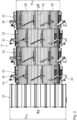
- the flame protection device 11 has a longitudinal axis 22 and at least one, in particular several, in particular four, ring arrangements 23 arranged one behind the other along the longitudinal axis 22.
- the flame protection device 11 is arranged in the drying drum 2 in such a way that the axis of rotation 3 and the longitudinal axis 22 coincide.
- the ring arrangements 23 are each designed identically. According to the exemplary embodiment shown, two ring arrangements 23 arranged adjacently along the longitudinal axis 22 are arranged with different rotation angle positions relative to the longitudinal axis.
- a corrugated ring arrangement 24 is arranged along the longitudinal axis 22 after the ring arrangements 23.
- the corrugated ring arrangement 24 can also be arranged at least partially overlapping and in particular completely overlapping with respect to the ring arrangements 23.
- the corrugated ring arrangement 24 can extend in the axial direction with respect to the longitudinal axis 22 along the length of the flame retardant device 11, i.e. in particular up to the first end wall 4.
- the corrugated ring arrangement 24 is arranged downstream with respect to the ring arrangements 23 in relation to the heat propagation direction 21.
- the corrugated ring arrangement 24 is particularly optional.
- the ring arrangements 23 each have an outer diameter D R,a , which is smaller than an inner diameter D i of the drying drum 2.
- D R,a ⁇ D i in particular D R,a ⁇ 0.9 x D i , in particular D R,a ⁇ 0.85 x D; and in particular D R,a ⁇ 0.8 x D;
- the corrugated ring arrangement 24 has an outer diameter D W,a , which essentially corresponds to the inner diameter D i of the drying drum 2.
- the outside diameter D W,a is larger than the outside diameter D R,a .
- D W,a > D R, a applies, in particular D W,a ⁇ 1.05 x D R,a and in particular D W,a ⁇ 1.1 x D R,a .
- the corrugated ring arrangement 24 comprises several, according to the exemplary embodiment shown, eighteen, double sheet metal elements 25, each of which is essentially concave with respect to the longitudinal axis 22 and has a substantially V-shaped contour.
- Two adjacently arranged double sheet metal elements 25 are connected to one another by means of connecting elements 42 arranged in the circumferential direction, whereby the closed corrugated ring arrangement 24 is formed and has a corresponding corrugated ring contour, which is particularly in Fig. 4 is visible.
- the corrugated ring arrangement 24 is designed to be particularly rigid and has a high level of stability. The risk that geometric deformations will occur on the corrugated ring arrangement 24 as a result of increased temperature changes is reduced.
- An optional baffle 26 is attached to the corrugated ring arrangement 24.
- the baffle 26 is designed in the shape of a disk and has a circular contour.
- the baffle 26 has a surface normal that is oriented parallel to the longitudinal axis 22.
- the baffle 26 is made in particular from a metal sheet.
- the baffle wall 26 is held on the corrugated ring arrangement 24 by means of at least one cross strut 27.
- two cross struts 27 are present.
- the cross struts 27 serve for additional transverse stiffening of the corrugated ring arrangement 24.
- the cross struts 27 are arranged transversely and in particular vertically with respect to the longitudinal axis 22.
- the cross struts 27 are arranged diametrically opposite one another with respect to the longitudinal axis 22.
- the baffle wall 26 has a diameter D P which is smaller than the diameter D W,a of the corrugated ring arrangement 24.
- the diameter D P of the baffle wall 26 is less than 90% of the inner diameter D i of the drying drum 2 and in particular less than 80% of that Inner diameter D i of the drying drum 2.
- D P ⁇ 0.75 x D i in particular D P ⁇ 0.7 x D i , in particular D P ⁇ 0.6 x D i , in particular D P ⁇ 0.5 x D; and in particular D P ⁇ 0.3 x D i .
- the baffle wall 26 is arranged approximately centrally on the corrugated ring arrangement 24 with respect to the longitudinal axis 22.
- the baffle 26 serves as an axial end element of the flame protection device 11, which is essentially hollow cylindrical.
- the ring arrangements 23 each have several, in particular identically designed, sheet metal lamellas 28.
- each ring arrangement 23 has eight sheet metal lamellas 28.
- adjacent sheet metal slats 28 are detachably connected to one another.
- finger-like coupling elements 29 are used, which protrude in the circumferential direction 31 about the longitudinal axis 22 on the sheet metal lamellas 28 in order to simplify the coupling with the adjacent sheet metal lamella 28.
- a sheet metal lamella 28 can be attached to the adjacent sheet metal lamella 28.
- the sheet metal lamella 28 is made in one piece overall and is manufactured in particular from a sheet metal blank by forming.
- the sheet metal lamella 28 has a concave inner contour 30, which, according to the exemplary embodiment shown, is designed to be curved at least in sections.
- the inner contour 30 can also be continuously curved and in particular designed as a circular line segment.
- the inner contour 30 is formed in particular by several metal strips 32 arranged next to one another in the circumferential direction 31.
- the sheet metal strips 32 are connected to one another in one piece and formed from a one-piece sheet metal blank, in particular by folding.
- a folded connection 41 is formed between two metal strips 32 adjacent in the circumferential direction 31.
- the folding connection 41 has a folding radius facing the inner contour 30 and is concave.
- the sheet metal lamella 28 has an installation element 33 which is integrally formed on the sheet metal lamella 28. In particular, this means that joints In particular, welded connections are avoided for fastening built-in elements to the sheet metal slats. The service life and in particular the high-temperature strength of the sheet metal lamella 28 is thereby increased.
- the built-in element 33 is arranged at the end in the circumferential direction 31 on one of the metal strips 32.
- the built-in element 33 is designed as a fold, in particular with a fold angle w of 90° relative to the metal strip 32.
- the built-in element 33 essentially extends as a crossbar to the sheet metal strip 32 on which the built-in element 33 is formed.
- a stabilizing web 34 is formed on the installation element 33 at an end opposite the metal strip 32. Due to the stabilizing web 34 and the sheet metal strips 32 arranged opposite the installation element 33, the installation element 33 essentially has the shape of a U-profile or an open rectangular profile.
- the built-in element 33 has a high level of inherent stability and rigidity.
- the installation element 33 has a connecting section which, according to the exemplary embodiment shown, is essentially formed by several, in particular five, connecting bores 35.
- the connecting holes 35 are arranged in the crossbar of the installation element 33 and enable a detachable connection of the sheet metal lamella 28 to an installation element 33 on the drying drum 2.
- a holder 36 is arranged on the inner wall 13 of the drying drum 2 and is particularly firmly attached, in particular welded, to the inner wall 13 of the drying drum 2.
- the holder 36 extends in particular in the radial direction with respect to the inner wall 13 and has a coupling section 37 with several openings which can be arranged in alignment with the connecting bores 35.
- the connection of the holder 36 to the installation element 33 is carried out by means of a retaining strip 37, fastening screws 38 guided through the connecting bores 35 and fastening nuts 39 each interacting therewith.
- the sheet metal slats 28 are each designed with a cone angle k relative to the holder 36. Accordingly, the respective ring arrangements 23 have a conicity which is in Fig. 1 is exaggerated. It is important that the ring arrangements 23 taper conically in the thermal expansion direction 21, i.e. towards the baffle wall 26.
- the ring arrangements 23 can be arranged in an overlapping manner along the longitudinal axis 22. A radial gap can result in an overlap region 40, which extends in particular in the circumferential direction 31, in particular over the entire circumference.
- the overlap region 40 extends along the longitudinal axis 22 over a maximum of 20% of the axial extent of a ring arrangement 23, in particular over a maximum of 15%, in particular over a maximum of 10% and in particular over a maximum of 5%.
- the overlap area 40 can also be omitted.
- the ring arrangements 23 are arranged without overlapping with respect to the longitudinal axis 22.
- the sheet metal slats 28 are arranged in the circumferential direction 31 in such a way that they rest against one another in the circumferential direction.
- the design of the ring arrangement 23 is thereby stiffened and particularly robust.
- a material deflector plate 43 is arranged on the outer sides of the sheet metal lamellas 28 and is in particular attached to the sheet metal lamella 28.
- the material deflector plates 43 are related to the material conveying direction 10 arranged upstream of the holder 36. This means that the holders 36 are each arranged in a shadow area which is formed by the material deflector plates 43 in relation to the material conveyance. As a result, the holders 36 are protected by the material deflector plates 43, in particular from RC granules in the drying drum 2.
- the material deflector plates 43 are optional.
- the material deflector plates are 43 in Fig. 5 to 7 Not shown.
- Emission-contaminated exhaust gas is returned to the drying drum 2 via the exhaust gas recirculation line 16, the blower 17 and the supply air line 18.
- the returned air is used to cool the flame protection device 11 in the drying drum 2.
- the flame protection device 11 serves to protect the RC material. In particular, it is prevented that the RC material has direct flame contact, i.e. falls in particular through the flame 6. In particular, direct radiation contact between the RC material and the flame 6 is minimized.
- the baffle wall 26, which represents axial radiation protection for the burner flame 6, serves this purpose in particular.
Landscapes
- Engineering & Computer Science (AREA)
- Mechanical Engineering (AREA)
- General Engineering & Computer Science (AREA)
- Chemical & Material Sciences (AREA)
- Combustion & Propulsion (AREA)
- Life Sciences & Earth Sciences (AREA)
- Sustainable Development (AREA)
- Physics & Mathematics (AREA)
- Thermal Sciences (AREA)
- Drying Of Solid Materials (AREA)
Applications Claiming Priority (1)
| Application Number | Priority Date | Filing Date | Title |
|---|---|---|---|
| DE102022202605.5A DE102022202605B4 (de) | 2022-03-16 | 2022-03-16 | Flammschutz-Vorrichtung und Trockentrommel mit einer derartigen Flammschutz-Vorrichtung |
Publications (1)
| Publication Number | Publication Date |
|---|---|
| EP4246071A1 true EP4246071A1 (fr) | 2023-09-20 |
Family
ID=85415235
Family Applications (1)
| Application Number | Title | Priority Date | Filing Date |
|---|---|---|---|
| EP23159535.6A Pending EP4246071A1 (fr) | 2022-03-16 | 2023-03-02 | Dispositif ignifuge et tambour de séchage doté d'un tel dispositif ignifuge |
Country Status (3)
| Country | Link |
|---|---|
| US (1) | US20230296319A1 (fr) |
| EP (1) | EP4246071A1 (fr) |
| DE (1) | DE102022202605B4 (fr) |
Cited By (2)
| Publication number | Priority date | Publication date | Assignee | Title |
|---|---|---|---|---|
| CN118089350A (zh) * | 2024-04-24 | 2024-05-28 | 山西泰宝科技有限公司 | 一种热风循环烘箱及控制方法 |
| CN119042959A (zh) * | 2024-11-04 | 2024-11-29 | 金维他(福建)食品有限公司 | 一种燕麦片生产用干燥装置及其工艺 |
Families Citing this family (3)
| Publication number | Priority date | Publication date | Assignee | Title |
|---|---|---|---|---|
| CN117232222B (zh) * | 2023-11-14 | 2024-02-02 | 江苏惠达电子科技有限责任公司 | 电子元器件风干装置及其控制方法 |
| IT202300024699A1 (it) * | 2023-11-21 | 2025-05-21 | Marini Spa | Impianto industriale per la produzione di conglomerati bituminosi. |
| CN118623579B (zh) * | 2024-08-13 | 2024-10-22 | 潍坊祥洲机械有限公司 | 一种饲料加工用烘干装置 |
Citations (7)
| Publication number | Priority date | Publication date | Assignee | Title |
|---|---|---|---|---|
| US4354826A (en) * | 1979-12-08 | 1982-10-19 | Metallgesellschaft Aktiengesellschaft | Process of drying and calcining bulk materials |
| US4919538A (en) * | 1989-07-26 | 1990-04-24 | Swisher Jr George W | Drum mixer having a combined mixing and heating zone |
| RU2027129C1 (ru) * | 1991-06-03 | 1995-01-20 | Могилевский Машиностроительный Институт | Барабанная сушилка |
| EP2202473A1 (fr) * | 2008-12-23 | 2010-06-30 | Bernardi Impianti International S.P.A. | Sécheur pour vrac inerte |
| EP2549016A1 (fr) * | 2011-07-20 | 2013-01-23 | Bernardi Impianti International S.P.A. | Séchoir à cylindre rotatif pour mélanges de matériaux de récupération et de gaz inertes vierges pour préparer des conglomérats bitumineux |
| EP3077749B1 (fr) * | 2013-12-04 | 2018-01-03 | Benninghoven GmbH & Co.KG Mülheim | Dispositif et procédé pour le réchauffage d'un granulat d'asphalte récupéré pour la production d'asphalte |
| EP3296462B1 (fr) * | 2016-09-16 | 2018-09-05 | Benninghoven GmbH & Co.KG Mülheim | Installation et procédé de fabrication d'asphalte |
Family Cites Families (3)
| Publication number | Priority date | Publication date | Assignee | Title |
|---|---|---|---|---|
| US4025057A (en) | 1972-11-03 | 1977-05-24 | Pavement Systems, Inc. | Equipment for making asphalt paving compositions |
| CN201186913Y (zh) | 2008-03-18 | 2009-01-28 | 西安达刚路面机械股份有限公司 | 冷态沥青混合料的新型加热装置 |
| DE102011002531A1 (de) | 2011-01-11 | 2012-07-12 | Benninghoven GmbH & Co.KG Mülheim | Doppel-Trockentrommel für die Herstellung von Asphalt sowie Verfahren zur Herstellung von Asphalt |
-
2022
- 2022-03-16 DE DE102022202605.5A patent/DE102022202605B4/de active Active
-
2023
- 2023-03-02 EP EP23159535.6A patent/EP4246071A1/fr active Pending
- 2023-03-15 US US18/184,444 patent/US20230296319A1/en active Pending
Patent Citations (7)
| Publication number | Priority date | Publication date | Assignee | Title |
|---|---|---|---|---|
| US4354826A (en) * | 1979-12-08 | 1982-10-19 | Metallgesellschaft Aktiengesellschaft | Process of drying and calcining bulk materials |
| US4919538A (en) * | 1989-07-26 | 1990-04-24 | Swisher Jr George W | Drum mixer having a combined mixing and heating zone |
| RU2027129C1 (ru) * | 1991-06-03 | 1995-01-20 | Могилевский Машиностроительный Институт | Барабанная сушилка |
| EP2202473A1 (fr) * | 2008-12-23 | 2010-06-30 | Bernardi Impianti International S.P.A. | Sécheur pour vrac inerte |
| EP2549016A1 (fr) * | 2011-07-20 | 2013-01-23 | Bernardi Impianti International S.P.A. | Séchoir à cylindre rotatif pour mélanges de matériaux de récupération et de gaz inertes vierges pour préparer des conglomérats bitumineux |
| EP3077749B1 (fr) * | 2013-12-04 | 2018-01-03 | Benninghoven GmbH & Co.KG Mülheim | Dispositif et procédé pour le réchauffage d'un granulat d'asphalte récupéré pour la production d'asphalte |
| EP3296462B1 (fr) * | 2016-09-16 | 2018-09-05 | Benninghoven GmbH & Co.KG Mülheim | Installation et procédé de fabrication d'asphalte |
Cited By (2)
| Publication number | Priority date | Publication date | Assignee | Title |
|---|---|---|---|---|
| CN118089350A (zh) * | 2024-04-24 | 2024-05-28 | 山西泰宝科技有限公司 | 一种热风循环烘箱及控制方法 |
| CN119042959A (zh) * | 2024-11-04 | 2024-11-29 | 金维他(福建)食品有限公司 | 一种燕麦片生产用干燥装置及其工艺 |
Also Published As
| Publication number | Publication date |
|---|---|
| DE102022202605B4 (de) | 2024-01-11 |
| DE102022202605A1 (de) | 2023-09-21 |
| US20230296319A1 (en) | 2023-09-21 |
Similar Documents
| Publication | Publication Date | Title |
|---|---|---|
| DE102022202605B4 (de) | Flammschutz-Vorrichtung und Trockentrommel mit einer derartigen Flammschutz-Vorrichtung | |
| EP3296462B1 (fr) | Installation et procédé de fabrication d'asphalte | |
| DE102015217845B4 (de) | Absaughaube zum Absaugen von Gas sowie Anlage zum Erwärmen von Material für die Asphaltherstellung umfassend eine derartige Absaughaube | |
| EP4155643A1 (fr) | Dispositif et procédé de séchage de matériau, ainsi qu'installation de mélange d'asphalte doté d'un tel dispositif | |
| EP4513119B1 (fr) | Dispositif de protection contre les flammes pour un brûleur et tambour de séchage doté d'un tel dispositif de protection contre les flammes | |
| DE3804815A1 (de) | Rostanordnung, insbesondere fuer stufenschwenkroste | |
| EP2347183B1 (fr) | Procédé et appareil pour l'extraction de produits de combustion d'un appareil de combustion | |
| EP0592477B1 (fr) | Dispositif de lavage de gaz de fumee | |
| EP3077749B1 (fr) | Dispositif et procédé pour le réchauffage d'un granulat d'asphalte récupéré pour la production d'asphalte | |
| DE2821637A1 (de) | Geblaeseschlaegermuehle | |
| EP0340462A1 (fr) | Four à tambour rotatif pour sécher ou mélanger des matériaux susceptibles de couler ou de ruisseler | |
| EP4717977A1 (fr) | Dispositif de protection contre les flammes pour un brûleur, lamelle pour un tel dispositif de protection contre les flammes et tambour de séchage doté d'un tel dispositif de protection contre les flammes | |
| EP3327349B1 (fr) | Générateur de gaz chaud permettant de chauffer un gaz ainsi qu'installation pour la production de bitume pourvue d'un tel générateur de gaz chaud | |
| EP0917640A1 (fr) | Tambour rotatif pour le sechage d'un materiau coulant | |
| EP0751347A1 (fr) | Four | |
| EP4357524B1 (fr) | Dispositif de protection contre les flammes pour un brûleur et tambour de séchage doté d'un tel dispositif de protection contre les flammes | |
| DD293514A5 (de) | Reinigungsmaschine | |
| DE666007C (de) | Rostfeuerung fuer vorgetrocknete Brennstoffe, deren feinkoernige Teile in der Schwebe verbrannt werden | |
| EP1477734B1 (fr) | Appareil de chauffage | |
| DE102010044129B4 (de) | Modulare Schottwand für einen Trommeltrockner sowie selbiger und Bausatz hierfür | |
| EP0097153B1 (fr) | Foyer de chaudiere | |
| DE10324058B4 (de) | Wärmetauscher sowie Heizkraftanlage | |
| DE9319897U1 (de) | Vorrichtung zum Trocknen und/oder Erwärmen von rieselfähigem Material | |
| WO2023046236A1 (fr) | Unité d'air de traitement pour le chauffage d'air de traitement | |
| DE102022005073A1 (de) | Flammenschutzvorrichtung für einen Brenner, Lamelle für eine derartige Flammenschutzvorrichtung und Trockentrommel mit einer derartigen Flammenschutzvorrichtung |
Legal Events
| Date | Code | Title | Description |
|---|---|---|---|
| PUAI | Public reference made under article 153(3) epc to a published international application that has entered the european phase |
Free format text: ORIGINAL CODE: 0009012 |
|
| STAA | Information on the status of an ep patent application or granted ep patent |
Free format text: STATUS: THE APPLICATION HAS BEEN PUBLISHED |
|
| AK | Designated contracting states |
Kind code of ref document: A1 Designated state(s): AL AT BE BG CH CY CZ DE DK EE ES FI FR GB GR HR HU IE IS IT LI LT LU LV MC ME MK MT NL NO PL PT RO RS SE SI SK SM TR |
|
| STAA | Information on the status of an ep patent application or granted ep patent |
Free format text: STATUS: REQUEST FOR EXAMINATION WAS MADE |
|
| 17P | Request for examination filed |
Effective date: 20231120 |
|
| RBV | Designated contracting states (corrected) |
Designated state(s): AL AT BE BG CH CY CZ DE DK EE ES FI FR GB GR HR HU IE IS IT LI LT LU LV MC ME MK MT NL NO PL PT RO RS SE SI SK SM TR |
|
| STAA | Information on the status of an ep patent application or granted ep patent |
Free format text: STATUS: EXAMINATION IS IN PROGRESS |
|
| 17Q | First examination report despatched |
Effective date: 20241118 |