EP4246745A1 - Sortie de conduite - Google Patents
Sortie de conduite Download PDFInfo
- Publication number
- EP4246745A1 EP4246745A1 EP22162306.9A EP22162306A EP4246745A1 EP 4246745 A1 EP4246745 A1 EP 4246745A1 EP 22162306 A EP22162306 A EP 22162306A EP 4246745 A1 EP4246745 A1 EP 4246745A1
- Authority
- EP
- European Patent Office
- Prior art keywords
- frame
- cover
- line outlet
- lid
- cassette
- Prior art date
- Legal status (The legal status is an assumption and is not a legal conclusion. Google has not performed a legal analysis and makes no representation as to the accuracy of the status listed.)
- Pending
Links
- 238000006073 displacement reaction Methods 0.000 claims description 14
- 238000004519 manufacturing process Methods 0.000 claims description 6
- 238000001746 injection moulding Methods 0.000 claims description 3
- 239000000126 substance Substances 0.000 claims description 2
- 230000000284 resting effect Effects 0.000 claims 1
- 229910052751 metal Inorganic materials 0.000 description 10
- 239000002184 metal Substances 0.000 description 10
- 238000007789 sealing Methods 0.000 description 5
- 238000009434 installation Methods 0.000 description 4
- 230000006378 damage Effects 0.000 description 3
- 239000006260 foam Substances 0.000 description 3
- 239000012790 adhesive layer Substances 0.000 description 2
- 239000000428 dust Substances 0.000 description 2
- 230000035515 penetration Effects 0.000 description 2
- 238000010146 3D printing Methods 0.000 description 1
- 229910001369 Brass Inorganic materials 0.000 description 1
- 229910001229 Pot metal Inorganic materials 0.000 description 1
- 208000027418 Wounds and injury Diseases 0.000 description 1
- HCHKCACWOHOZIP-UHFFFAOYSA-N Zinc Chemical compound [Zn] HCHKCACWOHOZIP-UHFFFAOYSA-N 0.000 description 1
- 238000004026 adhesive bonding Methods 0.000 description 1
- 229910052782 aluminium Inorganic materials 0.000 description 1
- XAGFODPZIPBFFR-UHFFFAOYSA-N aluminium Chemical compound [Al] XAGFODPZIPBFFR-UHFFFAOYSA-N 0.000 description 1
- 239000010951 brass Substances 0.000 description 1
- 238000005520 cutting process Methods 0.000 description 1
- 238000005034 decoration Methods 0.000 description 1
- 230000001419 dependent effect Effects 0.000 description 1
- 238000011161 development Methods 0.000 description 1
- 230000018109 developmental process Effects 0.000 description 1
- 238000004512 die casting Methods 0.000 description 1
- 230000000694 effects Effects 0.000 description 1
- 239000000835 fiber Substances 0.000 description 1
- 239000011888 foil Substances 0.000 description 1
- 208000014674 injury Diseases 0.000 description 1
- 238000000034 method Methods 0.000 description 1
- 238000004080 punching Methods 0.000 description 1
- 229910001220 stainless steel Inorganic materials 0.000 description 1
- 239000010935 stainless steel Substances 0.000 description 1
- 238000003860 storage Methods 0.000 description 1
- 238000003466 welding Methods 0.000 description 1
- 239000002023 wood Substances 0.000 description 1
- 229910052725 zinc Inorganic materials 0.000 description 1
- 239000011701 zinc Substances 0.000 description 1
Images








Classifications
-
- H—ELECTRICITY
- H02—GENERATION; CONVERSION OR DISTRIBUTION OF ELECTRIC POWER
- H02G—INSTALLATION OF ELECTRIC CABLES OR LINES, OR OF COMBINED OPTICAL AND ELECTRIC CABLES OR LINES
- H02G3/00—Installations of electric cables or lines or protective tubing therefor in or on buildings, equivalent structures or vehicles
- H02G3/02—Details
- H02G3/08—Distribution boxes; Connection or junction boxes
- H02G3/18—Distribution boxes; Connection or junction boxes providing line outlets
- H02G3/185—Floor outlets and access cups
-
- H—ELECTRICITY
- H02—GENERATION; CONVERSION OR DISTRIBUTION OF ELECTRIC POWER
- H02G—INSTALLATION OF ELECTRIC CABLES OR LINES, OR OF COMBINED OPTICAL AND ELECTRIC CABLES OR LINES
- H02G3/00—Installations of electric cables or lines or protective tubing therefor in or on buildings, equivalent structures or vehicles
- H02G3/02—Details
- H02G3/08—Distribution boxes; Connection or junction boxes
- H02G3/081—Bases, casings or covers
-
- H—ELECTRICITY
- H02—GENERATION; CONVERSION OR DISTRIBUTION OF ELECTRIC POWER
- H02G—INSTALLATION OF ELECTRIC CABLES OR LINES, OR OF COMBINED OPTICAL AND ELECTRIC CABLES OR LINES
- H02G3/00—Installations of electric cables or lines or protective tubing therefor in or on buildings, equivalent structures or vehicles
- H02G3/02—Details
- H02G3/08—Distribution boxes; Connection or junction boxes
- H02G3/14—Fastening of cover or lid to box
Definitions
- the invention relates to a line outlet, in particular for an underfloor duct and/or underfloor cassette.
- sockets are installed in the floor, they are usually arranged in a cassette or supply unit, the access opening of which is usually covered with a lid held in a frame.
- the cover must be largely closed even when in use, i.e. when one or more cables are led out of the cassette or supply unit.
- a cable outlet limits the opening for the electrical cable to run through.
- the cables of the connected electrical devices must also be protected by the cable outlet on the cover against damage caused by loads on the cover or the cable outlet, without creating a tripping hazard.
- the line outlet must therefore be able to safely hold two positions, closed and open.
- Known line outlets 100 such as the one in the Figures 1 to 4
- the type shown is composed of a large number of components and is therefore complex and expensive to produce.
- the handle 131 provided for lifting is not very aesthetically pleasing, and dirt can easily collect in the recess 150 required to grip the handle 131, which is difficult to remove.
- the known line outlet 100 in the open position also requires a counter bearing on which the raised line outlet 100 rests and is supported, for example the frame of the underfloor cassette 10, highlighted in the figure by the dashed ovals. This can lead to damage to the cassette frame, which may not necessarily affect the function, but definitely affects the appearance.
- Figure 3 shows a view of a known line outlet 100 before assembly on a cassette cover 20, not shown in the figure, in an open position.
- the walls of the frame 102 are formed from a stamped and bent sheet metal part.
- the frame sides 104a, 104b of the frame 102 are particularly visible.
- Figure 4 shows the well-known line outlet 100 in an exploded view. It is clearly visible that the frame 102 is made from a punched and bent sheet metal part.
- the lid 130 comprises a punched and bent sheet metal part 130-1, into which a pivot axis 160 is inserted and to which a lid top 134 is glued using an adhesive layer 133.
- a screw 161 is used to attach a ground cable.
- the handle 131 is movably guided in holes in the sheet metal part 130-1 of the lid 130 and the top of the lid 134, with cap nuts 131-1 forming a stop.
- a sealing element 200 for example made of a foam or formed by a brush, is mounted, for example glued, in the sheet metal part 130-1.
- the known line outlets are usually made from several sheet metal blanks or stamped parts, which usually have one or more folds. If the sheet metal cuts are not in one piece, they are joined together by welding, gluing or screwing and mounted as an assembly on the cassette cover, for example welded or screwed. Guides, contact points, etc. have to be implemented using notches, pins, etc., which results in high manufacturing costs in addition to the already high number of individual parts. When punching the sheet metal blanks, sharp edges can arise, which must be processed in additional steps to reduce the risk of injury. Since the cable outlet is usually welded to the cassette cover, replacement is not possible or only possible with considerable effort if it is damaged. Typically, the entire cover is replaced along with the floor covering attached to it, which entails further additional effort when restoring the floor covering.
- a line outlet for an underfloor duct or an associated underfloor cassette or supply unit comprises a frame and a cover movably mounted in the frame.
- the cover has guide elements on two opposite sides, which are guided in corresponding contours of a link guide on two opposite sides of the frame.
- Two first guide elements located on opposite sides of the lid form a pivot axis which runs essentially parallel to the surface of the lid.
- the guide elements which are preferably firmly connected to the sides of the lid or are integral parts thereof, are guided in the contours so that the pivot axis can be moved along the opposite sides of the frame between a first, closed and a second, open position of the lid.
- a first section of the contour of the link guide is designed such that the displacement of the pivot axis from the first, closed position of the lid into the second, open position of the lid initially involves a component that runs essentially perpendicular to an upper edge of the frame having. This means that the lid, the top of which, for example, in the first, closed position is essentially flush with an upper edge of the frame, when opened it is initially raised as a whole and essentially parallel to its original position or orientation.
- the first section of the contour of the link guide preferably guides the first guide element.
- a second section of the contour of the link guide is designed such that the displacement of the pivot axis from the first, closed position of the lid into the second, open position of the lid is parallel to the upper edge of the frame and perpendicular to the Component running at the top edge of the frame.
- the cover is moved away from a side of the frame that runs parallel to its pivot axis, so that a pivoting movement is made possible without the cover having to be raised far above an upper edge of the side of the frame that runs parallel to its pivot axis.
- the second section preferably follows the first section.
- a translational movement of the first guide elements in a direction perpendicular to the surface of the lid is limited by a stop in the contour of the link guide, so that only a rotational movement around that formed by the two first guide elements Swivel axis is possible.
- second guide elements can be provided, which are arranged at a distance from the first guide elements on the sides of the lid, and which are in the corresponding position at least during part of the movement of the lid from the first, closed position to the second, open position Sections of the contours of the backdrop guide are guided.
- the guidance can also simply consist of the second guide elements abutting against a stop.
- the second guide elements are guided in a contour of the link guide in such a way that a rotational movement of the cover about the pivot axis in the first intermediate position is limited.
- a stop can be provided in the contour. A shift parallel to the upper side edge of the frame remains possible.
- support elements with a support surface are provided on the lid.
- the support surface of the support element can be pushed onto a support surface of the frame in the first intermediate position of the lid by moving parallel to a lateral upper edge of the frame.
- the support surface can also be formed by the frame itself, for example its upper edge, or a projection provided thereon.
- the support elements can also be third guide elements, which are guided in a contour of the link guide and support the guidance of the translational and/or rotational movement of the lid.
- the support surface of each of the support elements can be limited by a stop, which prevents the support surface from being pushed further onto the frame or the projection provided thereon, but allows the cover to pivot.
- first locking contours are provided on the sides of the cover, which in the second, open position of the cover are each positioned relative to a correspondingly shaped second locking contour of the frame so that a displacement of the support elements parallel to a lateral upper edge of the frame and / or the first guide elements of the cover are prevented perpendicular to the lateral upper edge of the frame when the support surface of the support elements rests on the frame.
- the first and second locking contours can be designed in such a way that they can be separated from one another by a pivoting movement of the lid in the second, open position.
- the first locking contours can be arranged on the first guide elements, which form the pivot axis of the lid. When the first and are separated from each other With the second locking contours, the pivot axis of the cover can be moved in the contour of the link guide.
- the lid has a recess or recess, which can be closed by a cover pivotably mounted in the recess or recess.
- the pivotally mounted cover can be used in the swiveled open position as a handle with which the cover can be moved from the first, closed position to the second, open position and vice versa.
- the pivot axis preferably runs parallel to the lid surface.
- a surface of the cover When closed, a surface of the cover preferably lies essentially in the same plane as the surface of the lid.
- the pivot axis of the cover is arranged at a distance from its sides running parallel to it, so that the cover pivots open by a force acting perpendicular to the surface of the cover on the side of the pivot axis and an edge of the cover pivoting out of the recess can thus be grasped as a handle is.
- the pivot axis of the cover can be arranged on one of the sides of the cover running parallel thereto, and the cover can be pivoted into the recess.
- the recess extends under the side of the lid surface opposite the pivot axis, so that an undercut is created, which can be used as a handle.
- the cover can be brought into the closed position in the unloaded state, for example by a spring.
- the spring can also provide the pivot axis at the same time, for example if it is designed as a leaf spring.
- a locking device is actuated by pivoting open the cover, which enables movement of the cover of the line outlet.
- a latch can be connected to the cover, which engages in the frame when the cover is closed, at least when the lid is closed, and prevents movement.
- the cover and/or the frame are manufactured using a pressure or injection molding process.
- the cover surface, the surface of the cover and/or at least visible parts of the frame have an appearance that differs from the surface present after production due to a mechanical, chemical or electrochemical treatment.
- the lid, the frame and/or the cover can be made from a zinc or aluminum die-cast or a plastic injection molding, which after production has a stainless steel or brass look through an appropriate treatment or a different design through a glued-on film receives.
- projections are provided on the outside of the frame sides and/or the rear wall of the frame, which, when the frame is positioned on the top of the cassette lid, rest on this top side and block movement of the frame towards the top of the cassette lid.
- the projections can be designed like ribs and transmit forces to the cassette lid.
- one or more tabs protrude from the lower edge of the rear frame wall, which have one or more first structures on a top side pointing towards the top of the lid, which, when the frame is positioned on the top of the cassette lid in an end position, engage corresponding second structures accessible from the underside of the cassette lid and prevent movement of the frame parallel to the surface of the cassette lid.
- fastening means can be inserted into the first structures from the top of the cassette lid through the second structures in order to fix the frame to the cassette lid.
- fastening means can be connected to the cassette cover from the underside through the first structures, e.g. screws.
- the first structures can therefore also include holes in the tabs.
- the frame has guide elements on its outside, along which a frame extension can be guided in a displaceable manner perpendicular to the top of the cover of the line outlet.
- receptacles for fixing means can be provided, by means of which the frame extension can be fixed to the frame.
- the fixing means are, for example, threads provided in the guide elements, into which a screw screwed from the outside through the frame extension engages and thus presses the frame extension against the frame.
- a frame extension has a body wall which surrounds the frame from the outside following its contour, wherein the body wall does not completely enclose or enclose the frame.
- the frame extension can encompass the frame in a C-shape, for example. Slots or recesses are also provided in the body wall, in which the guide elements arranged on the outside of the frame can be received and guided. From a first end of the body wall, which faces towards the top when the frame is accommodated therein, two or more fastening tabs protrude outwards, preferably substantially at right angles.
- the fastening straps can be provided with holes for screws or similar fasteners.
- the frame of the line outlet is guided in the frame extension, preferably perpendicular to the top of the cassette cover, so that it can be moved and fixed.
- the slots or recesses can extend to the top edge of the body wall, so that the guide elements of the frame can be inserted into the slots from the top of the frame extension.
- the slots or recesses are preferably arranged in areas of the body wall in which a fastening tab is also arranged.
- the fastening tab extends preferably on both sides of a respective slot or a respective recess, so that the wall areas separated from the slot or recess are held together by the fastening tab. If necessary, the slot or recess can extend slightly into the fastening tab.
- the line outlet essentially consists of three die-cast parts, for example die-cast zinc, namely the cover, the lid and the frame.
- the contours of the link guide are integrated into the die-cast part, just as the guide means are integrated into the cover.
- the lid and frame are therefore made in one piece. Due to the guidance of the guide elements in the contours and the integrated support of the cover on the frame, no counter bearing is necessary on or on the cassette frame.
- the cable outlet can also be used without a frame, for example mounted on a flat surface.
- the lids can be used without changes.
- the lid and frame are forcibly joined and locked. Only the cover is secured in the lid with screws, so production only requires a few steps.
- the frame of the cable outlet can be pushed in from the edge of the cassette cover and fixed on the inward-facing edge with screws that engage the cassette cover from below. Strips on top of the cassette lid hold the frame securely even under load. On the edge side of the frame, projections projecting outwards can be provided, which engage in corresponding recesses in the edge of the lid and thus prevent upward movement.
- a surface of the line outlet that is exposed on the top can simply be covered with suitable decorations, for example with a metal foil, a wood veneer or the like.
- Fig. 5 shows a view of a line outlet 100 according to the invention in a cassette cover 20 of an underfloor cassette 10 (not shown in the figure) in a first, closed position.
- a cover 130 is stored in the frame 102.
- the lid 130 has a recess 150 (not visible in the figure), which is covered with a cover 152.
- a surface of the cover 152 is preferably aligned substantially parallel, particularly preferably flush, with the surface 134 of the lid.
- One or more projections 300 are arranged on the outside of the frame sides 104a, 104b or the frame rear wall 104, which, when the frame 102 is positioned on the top of the cassette lid 20, rest on this top side and prevent the frame 102 from moving towards the top of the cassette lid 20 To block.
- Two tabs 302 protrude from the lower edge of the rear side of the frame 104, preferably at least in sections parallel to the top of the lid 130.
- the tabs 302 have one or more first structures 304, which have corresponding second structures 306 accessible from the underside of the cassette lid 20 directly or indirectly cooperate and prevent movement of the frame 102 parallel to the surface of the cassette lid 20.
- the second structures 306 can be, for example, bores or holes.
- a direct cooperation of the first and second structures 304, 306 can take place, for example, through pins which engage in the bores or holes in the cassette cover 20 and protrude from the top of the tabs 302.
- the pin can also be designed as a rivet, the head of which is only formed after the line outlet 100 has been correctly installed in the cassette cover 20.
- first and second structures 304, 306 can be brought about, for example, by screws which are guided from the underside through holes in the tabs 302 and screwed into the cassette lid 20 when the frame 102 is on the top of the cassette lid 20 in one End position is positioned to fix the frame on the cassette lid 20.
- the holes in the tabs 302 form the first structures 304.
- FIG. 6 shows a representation of the line outlet 100 according to the invention in the first, closed position with the first frame side 104a partially removed and visible contours 106 of a link guide.
- the line outlet 100 includes, as already referred to Figure 5 described, a frame 102 and a lid 130.
- Lid 130 has a recess 150, not visible in the figure, which is covered by a cover 152.
- contours 106 of a link guide can be seen, in which first, second and third guide elements 136, 138 and 140 arranged on the sides of the cover 130 are guided.
- the contours form a flat relief, the outer sides of the side walls 104a, 104b of the frame 102 are closed.
- the imaginary connecting line of the first guide elements 136 opposite each other on the sides of the cover 130 forms a pivot axis 160, indicated by the dash-dotted line.
- the tabs 302 can also be seen more clearly, on the upper sides of which screws guided by the first structures 304, which are designed as bores, are indicated.
- the contours 106 and the first, second and third guide elements 136, 138 and 140 are respectively provided on the second frame side 104b of the frame 102 and the corresponding side of the lid.
- Figure 7 shows a detailed representation of the inner side of a second frame side 104b of the line outlet 100 according to the invention Figure 6 with parts of first, second and third guide elements 136, 138 and 140 of the cover 130.
- the design of the contours 106 of the frame 102 can be seen in particular as a flat relief.
- the first, second and third guide elements 136, 138 and 140 of the lid end in the recessed areas of the contours 106. Together with the otherwise largely closed side walls of the lid 130, which are guided between the sides 104a and 104b of the frame 102, this is the case good lateral guidance is ensured, which ensures jam-free opening and closing of the lid 130 despite the displaceability of the pivot axis 160.
- a special shape of the part of the contour 106 is also visible, in which the first guide element 136 is guided.
- a first section 106a in which the first guide element 136 is guided essentially at a right angle to an upper edge of the frame 102, is followed by a second section 106b, in which the first guide element 136 also moves away from the frame rear wall 104 executes.
- the first guide element 136 is also designed so that a pivoting movement in the first section 106a and in parts of the second section 106b of the contour 106 is not possible. This is achieved, for example, by a shape that is not completely round.
- FIG 8 shows a representation of the line outlet 100 according to the invention Figure 6 in the first, closed position with the cover 152 raised, a recess 150 in the cover 130.
- the cover 152 swings open around a pivot axis, so that the area of the cover 152 that swings out can be used as a handle.
- the pivoted out edge of the cover 152 is also slightly thickened.
- Figure 9 shows a representation of the line outlet 100 according to the invention with a cover 130 moved out of the first, closed position. It can be clearly seen how, in particular, the shape of the first guide element 136, together with the front edge of the third guide element 140, in their respective contours 106, a pivoting movement of the Prevent lid 130, and after a short straight upward movement in the direction of arrow A, only allow a longer oblique upward movement in the direction of arrow B.
- the upward movement in the direction of arrow A preferably runs at least over a distance which corresponds to the thickness of the top of the lid, designated C in the figure. In this way, the top of the lid 130 can be flush with the upper edge of the frame rear wall 104, and the gap between the lid 130 and the frame rear wall 104 can be kept small in the closed position of the lid 130.
- Figure 10 shows a detailed representation of a frame side of the line outlet 100 according to the invention Figure 9 with parts of the first, second and third guide elements 136, 138 and 140 of the lid 130.
- first guide element 136 effectively prevents a pivoting movement of the lid 130, supported by the front edge of the third guide element 140.
- the second Guide element 138 could also contribute to preventing a pivoting movement of the lid 130 if the side of the contour 106 lying between the second and third guide elements 138 and 140 facing it had a corresponding inclination.
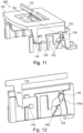
- Figure 11 shows a representation of the line outlet 100 according to the invention with the cover in a first intermediate position.
- the first and third guide elements 136 and 140 prevented the cover 130 from pivoting until the first intermediate position was reached.
- the first guide element 136 rests with an upper edge against a stop in the contour 106, so that further upward movement is not possible.
- the hook-like extension of the first guide element 136 which forms a first locking contour 136a, now lies completely in a free space of the contour 106, so that a rotational movement of the pivot axis 160 created by the first guide elements 136 arranged on both sides of the cover 130 is possible.
- Figure 12 shows a detailed representation of a frame side of the line outlet 100 according to the invention Figure 11 with parts of guide elements 136, 138 and 140 of the cover 130.
- FIG. 12 shows a detailed representation of a frame side of the line outlet 100 according to the invention Figure 11 with parts of guide elements 136, 138 and 140 of the cover 130.
- the upper edge of the first guide element 136 abuts one end of the contour 106, so that further upward movement is no longer possible. Only a rotational movement about the pivot axis 106 is possible.
- a second council contour 112 that matches the first locking contour 136a can also be seen in this illustration. Their function is explained in more detail below.
- Figure 13 shows a representation of the line outlet 100 according to the invention with the cover 130 in a second intermediate position.
- the second intermediate position is achieved by a rotational movement of the cover 103 about the pivot axis 160, which is limited by the second guide element 138 striking a stop on the contour 106.
- Figure 14 shows a detailed representation of a frame side of the line outlet 100 according to the invention Figure 13 with parts of guide elements 136, 138 and 104 of the cover 130.
- the support surface 144 can be pushed onto the support surface 111 of the frame 102 after pivoting about the pivot axis formed by the opposite second guide elements 138.
- the second guide element 138 prevents the cover 130 from pivoting further about the pivot axis 160.
- Figure 15 shows a representation of the line outlet 100 according to the invention shortly before reaching the second, open position with the first frame side 104a partially removed and visible contours of a link guide 106.
- the cover 130 is already pivoted about the pivot axis formed by the opposite second guide elements 138 and parallel to the upper edge 110 of the frame 102 shifted so that the support surface 144 is located above the support surface 111.
- the displacement of the cover 130 parallel to the upper edge 110 of the frame 102 is limited by a stop 146 which abuts an edge of the support surface 111.
- the first guide element 136 By pivoting about the pivot axis formed by the opposite second guide elements 138 and the displacement of the cover 130 parallel to the upper edge 110 of the frame 102, the first guide element 136 is in one of the first and second sections 106a, 106b of the contour 106 adjacent third section 106c.
- the first locking contour 136a is positioned in relation to the second locking contour 112 so that when the cover 130 is lowered and after a shift parallel to the upper edge 110 of the frame 102 in the opposite direction to the previous shift, they interlock and turn the cover 130 against a pivoting movement secure the pivot axis 160 and/or an axis formed by the contact points 111 and 144.
- Figure 16 shows a detailed representation of a second frame side 104b of the line outlet 100 according to the invention Figure 15 with parts of guide elements 136, 138 and 140 of the cover 130.
- the positioning of the support surface 144 above the support surface 111 and the contact of the stop 146 on the edge of the corresponding contour 106 can be clearly seen.
- the positioning of the first ratchet contour 136a in relation to the second locking contour 112 is also clearly visible.
- it is clear in this illustration how a pivoting movement around the point at which the stop 146 rests on the corresponding contour 106 and a lowering of the cover 130 will bring the first and second locking contours into engagement with one another.
- Figure 17 shows a representation of the line outlet 100 according to the invention in the second, open position with the first frame side 104a partially removed and visible contours 106 of a link guide.
- the support surface 144 rests on the support surface 111 and holds the lid 130 in the open position.
- the first and second locking contours 136a, 112 are in engagement with one another, so that the cover 130 is prevented from being lifted in the vicinity of the pivot axis 160.
- the cover 152 is still open, but can now be closed again so that the line outlet 100 can remain in the open position and cannot be opened unintentionally.
- Figure 18 shows a detailed representation of the second frame side 104b of the line outlet 100 according to the invention Figure 17 with parts of guide elements 136, 138 and 140 of the lid 130. Particularly easy to see Here are the engaged first and second locking contours 136a, 112 and the support of the support surface 144 on the support surface 111.
- Figure 19 shows a further representation of the line outlet 100 according to the invention in the second, open position with the first frame side 104a partially removed and visible contours of a link guide.
- first and second locking contours 136a, 112 engage and the support surface 144 is supported on the support surface 111.
- Figure 20 shows a view of the line outlet 100 according to the invention in an underfloor cassette 10 in the second, open position.
- Line outlet 100 is inserted into the cassette cover 20, of which only the edge is visible here.
- the cover 152 of the lid 130 of the line outlet 100 is closed and is essentially flush with the lid surface 134.
- the opening formed by the opened cover 130 is secured with a sealing element 200 against the penetration of dust and dirt into the underfloor cassette 10.
- the sealing element 200 can include, for example, a brush or a flexible foam element. Lines and cables locally displace the fibers of the brush or the foam element, so that the majority of the opening remains closed.
- Figure 21 shows a representation of the line outlet 100 according to the invention after a first step when leaving the second, open position with the first frame side 104a partially removed and visible contours 106 of a link guide.
- the cover 130 was first pivoted about the pivot axis 160 so that the support surface 144 no longer rests on the support surface 111, and then pushed in the direction of the opening of the line outlet 100.
- the first and second locking contours 136a, 112 are now no longer engaged, and the first guide element 136 can be moved upwards in the direction of arrow D.
- Figure 22 shows a detailed representation of the second frame side 104b of the line outlet 100 according to the invention Figure 21 with parts of Guide elements 136, 138 and 140 of the lid 130. The description of the elements visible in the figure corresponds to that of Figure 21 .
- Figure 23 shows a representation of the line outlet 100 according to the invention with the cover 130 in the second intermediate position.
- the first guide element 136 was along the in Figure 22 arrow D shown is shifted upwards until it abuts the contour 106. Due to the displacement, the support surface 144 is also moved away from the support surface 111, so that the third guide element 140 can now be moved into the corresponding contour 106 when the cover 130 is pivoted downwards about the pivot axis 160.
- Figure 24 shows the lid 130 in the pivoted-down position. Since the front edge of the third guide element 140 limits the pivoting movement, the cover 130 is now essentially parallel to the upper edge 110 of the frame 102.
- Figure 25 shows a representation of the line outlet 100 according to the invention with a cover 130 moved out of the first intermediate position on the way to the first, closed position of the cover 130.
- Figure 26 shows a representation of the cover 130 of the line outlet 100 according to the invention, which has again reached the first, closed position, with the first frame side 104a partially removed and visible contours 106 of a link guide. This representation corresponds to that of Figure 6 .
- Figure 27 shows a representation of the frame 102 and the contours 106 of the link guide arranged therein.
- the contours 106 of the link guide form parts of the frame sides.
- Projections 300 can be seen, with which the frame 102 is supported on the cassette lid 20, as well as parts of the tabs 302, which reach under the cassette lid 20 from below.
- the frame can be manufactured, for example, using a die-casting process, using metal-cutting processes or using 3D printing.
- Figure 28 shows a detail of the second frame side 104b with the contours 106 of the link guide and parts of guide elements 136, 138 and 140 of the cover 130 guided therein.
- the frame shown in the figure is higher than the frames shown in the other figures.
- the height can be easily adjusted without changing the contours 106 and the cover 130 with its guide elements 136, 138 and 140, while the design effort remains low. A greater height may be necessary, for example, if the floor covering is particularly thick.
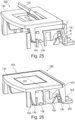
- Figure 29 shows an illustration of an exemplary attachment of the pivotable cover 152 of the recess 150 or recess in the cover 130.
- the line outlet 100 is shown mounted from its underside in a cassette cover 20.
- the depression itself 150 is not visible in this view.
- the cover 152 has two laterally projecting axle stubs 154, which are movably mounted in a corresponding bearing structure 156 provided on the underside of the cover 130. Screws 158 secure the cover 152 from falling out.
- the tabs 302 which reach from the underside of the frame 102 under the cassette cover 20 (because of the view from below in the figure over the top).
- the tabs 302 may be connected to the cassette lid 20 with fasteners, such as screws, as shown in the figure.
- Sealing element 200 ensures a seal against the penetration of dust and dirt into the underfloor cassette when the cable outlet 100 is open, even when cables and lines are passed through.
- variable frame extension can be used in one or more configurations.
- Figure 30 shows a frame extension 170 according to the invention for a line outlet according to the invention.
- the frame extension 170 includes three body walls 172, which limit the frame extension 170 on three sides.
- the frame extension 170 is open to a fourth side.
- Tabs 178 are arranged on the body walls 172, with which the frame extension 170 can be attached to a surface, for example a cassette lid of an underfloor cassette.
- the tabs 178 can, for example, have holes for screws to pass through.
- Slots or recesses 174 are provided in the body walls, in which a guide element of the line outlet 100 can be slidably received.
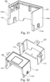
- Figure 31 shows one for use with the frame extension 170 according to the invention Figure 30 set up line outlet 100.
- the line outlet 100 is essentially identical to the line outlets 100 described above. The identical elements are not described again here.
- guide elements 114 are arranged on the outer sides of the first and second frame sides 104a, 104b, which protrude outwards from the respective frame wall 104a, 104b and which, in the assembled state, with the slots or recesses 174 or edges of the body walls 172 of the frame extension 170 work together and guide the line outlet 100 in the frame extension 170 so that it can be moved.
- the guide elements 114 are designed in such a way that the line outlet 100 is prevented from tilting in the frame extension 170.
- Figure 32 shows the frame extension 170 according to the invention Figure 30 and the line outlet 100 according to the invention adapted for use with the frame extension 170 in a position before assembly.
- the two opposite body walls 172 In order to insert the line outlet 100 into the frame extension 170, the two opposite body walls 172 must be moved apart slightly in the direction of the double arrow E so that the line outlet 100 can be inserted into the frame extension 170 in the direction of the arrow F and the guide elements 114 into the Slots or recesses 172 can engage or rest against the respective front edges of the opposite body walls 172.
- Figure 33 shows the frame extension 170 according to the invention Figure 30 and the line outlet 100 according to the invention adapted for use with the frame extension 170 in a position during assembly.
- the body walls 172 must be moved apart slightly in the direction of the arrows E so that the line outlet 100 can be completely inserted into the frame extension 170 and the guide elements 114 can get into the slots or recesses 174.
- Figure 34 shows the line outlet 100 according to the invention assembled with the frame extension 170 according to the invention in a first view. In this illustration it is clearly visible how the guide elements 114 are guided in the slots or recesses 174 or lie against the front edge of the body walls 172. A displacement of the line outlet 100 in the direction of arrow G remains possible.
- Figure 35 shows a second view of the line outlet 100 according to the invention assembled with the frame extension 170 according to the invention. This illustration also clearly shows how the guide elements 114 are guided in the slots or recesses 174 or rest on the front edge of the body walls 172, and how a displacement of the Line outlet 100 in the direction of arrow G remains possible.
- the Figures 34 and 35 also show how the design of the guide elements 114 can prevent the line outlet 100 from tilting in the frame extension 170, even if the line outlet 100 is pushed into the top position.
- Figure 36 shows a view of the line outlet 100 according to the invention assembled with the frame extension 170 according to the invention and fixed thereon.
- Figure 37 shows a view of the line outlet 100 according to the invention assembled with the frame extension 170 according to the invention and fixed thereon after installation in an opening 402 in a thin surface 400.
- the frame extension 170 is screwed to the surface 400 from below with screws 184.
- Figure 38 shows a view of the frame extension 170 according to the invention installed in the opening 402 in the surface 400 with the line outlet 100 according to the invention fixed therein, seen from the underside.
- the screws 184 guided through holes in the tabs 178 to fasten the frame extension 170 can be clearly seen.
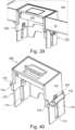
- Figure 39 shows a view of the line outlet 100 according to the invention assembled with the frame extension 170 according to the invention and fixed thereto after installation in an opening 402 in a thick surface 400.
- the frame extension 170 is screwed to the surface 400 from below with screws 184.
- the thick surface 400 in this case is a thin surface with walls that extend upwards like a trough, for example the bottom of a cassette lid 20, which is filled with a floor covering after assembly.
- the line outlet 100 has been moved upwards in the frame extension 170 and fixed there.
- Figure 40 shows an illustration of an alternative frame extension 170 according to the invention with a line outlet 100 according to the invention accommodated therein.
- Guide elements 114 are arranged on the first and second frame sides 104a, 104b, which protrude outwards from the respective frame wall 104a, 104b.
- the guide elements 114 engage displaceably in corresponding slots or recesses 174 in the frame extension 170 or are guided displaceably along an edge of the body wall 172 of the frame extension 170.
- the guide elements 114 are designed in such a way that the line outlet 100 is prevented from tilting in the frame extension 170.
- the frame extension 170 is connected to the cassette lid 20 (not shown in the figure), for example by fastening tabs 178 which are screwed to the cassette lid 20.
- the slots or recesses 174 in the body walls 172 extend to the upper edge of the frame extension, so that the line outlet 100 can easily be inserted from above.
- the line outlet 100 can be fixed, for example, using screws whose heads rest on the outside of the body wall 172 (not shown in the figure).
- a thread can be provided in the guide elements 114.
- the screws can be countered from the inside.
- the outside of the body wall 172 can be structured, for example with horizontal grooves (not shown in the figure).
- a part provided with a corresponding structure and a hole through which the screw is passed can be arranged between the screw head and the outside of the body wall 170.
- the structures can interlock positively and thus prevent displacement of the line outlet 100 in the frame extension 170 even if the screw is not tightened very tightly.
Landscapes
- Engineering & Computer Science (AREA)
- Architecture (AREA)
- Civil Engineering (AREA)
- Structural Engineering (AREA)
- Connector Housings Or Holding Contact Members (AREA)
Priority Applications (1)
| Application Number | Priority Date | Filing Date | Title |
|---|---|---|---|
| EP22162306.9A EP4246745A1 (fr) | 2022-03-15 | 2022-03-15 | Sortie de conduite |
Applications Claiming Priority (1)
| Application Number | Priority Date | Filing Date | Title |
|---|---|---|---|
| EP22162306.9A EP4246745A1 (fr) | 2022-03-15 | 2022-03-15 | Sortie de conduite |
Publications (1)
| Publication Number | Publication Date |
|---|---|
| EP4246745A1 true EP4246745A1 (fr) | 2023-09-20 |
Family
ID=80780866
Family Applications (1)
| Application Number | Title | Priority Date | Filing Date |
|---|---|---|---|
| EP22162306.9A Pending EP4246745A1 (fr) | 2022-03-15 | 2022-03-15 | Sortie de conduite |
Country Status (1)
| Country | Link |
|---|---|
| EP (1) | EP4246745A1 (fr) |
Citations (3)
| Publication number | Priority date | Publication date | Assignee | Title |
|---|---|---|---|---|
| WO2005026481A2 (fr) * | 2003-09-11 | 2005-03-24 | Southco, Inc. | Verrou pour plancher porteur |
| DE102010048002A1 (de) * | 2010-10-08 | 2012-04-12 | Kindermann Gmbh | Anschlusskasten |
| EP3407444A1 (fr) * | 2017-05-23 | 2018-11-28 | Simon, S.A.U. | Mécanisme d'ouverture et de fermeture du couvercle d'un logement |
-
2022
- 2022-03-15 EP EP22162306.9A patent/EP4246745A1/fr active Pending
Patent Citations (3)
| Publication number | Priority date | Publication date | Assignee | Title |
|---|---|---|---|---|
| WO2005026481A2 (fr) * | 2003-09-11 | 2005-03-24 | Southco, Inc. | Verrou pour plancher porteur |
| DE102010048002A1 (de) * | 2010-10-08 | 2012-04-12 | Kindermann Gmbh | Anschlusskasten |
| EP3407444A1 (fr) * | 2017-05-23 | 2018-11-28 | Simon, S.A.U. | Mécanisme d'ouverture et de fermeture du couvercle d'un logement |
Similar Documents
| Publication | Publication Date | Title |
|---|---|---|
| DE60101923T2 (de) | Kabelkanalsystemscharnieranordnung | |
| DE69705662T2 (de) | Rollvorrichtung für Schiebetüren, Fenster oder ähnliches | |
| AT520765B1 (de) | Schubladenseitenwand mit einem Abdeckprofil | |
| DE69402240T2 (de) | Rinne mit einer Abdeckungsverbindung mit Verriegelungsvorrichtung, insbesondere für elektrische Geräte | |
| DE19717184A1 (de) | Schublade | |
| CH663336A5 (de) | Kasten. | |
| AT15577U1 (de) | Band für eine Tür oder ein Fenster | |
| DE69411452T2 (de) | Vorrichtung zum Befestigen und Seitenjustieren der Frontverkleidung einer Schublade | |
| DE102016121074B3 (de) | Sammelschienenhalter und eine entsprechende Anordnung | |
| DE8202450U1 (de) | Werkzeug zum Herausziehen eines Elektronikeinschubs aus einem Haltegestell | |
| DE3871807T2 (de) | Scharnier. | |
| EP3332133A1 (fr) | Écrou prisonnier | |
| DE4018235C2 (fr) | ||
| DE60035224T2 (de) | Verriegelungsvorrichtung und verfahren zu deren herstellung | |
| AT520803B1 (de) | Schubladenseitenwand | |
| EP3327240B1 (fr) | Dispositif de maintien pour maintenir un dispositif de protection solaire et système de maintien | |
| DE3131537A1 (de) | "eckverbindung" | |
| DE69510627T2 (de) | Geräteträgereinrichtung Einzubringen auf einen Kabelkanalkörper | |
| DE3913319C2 (fr) | ||
| CH715007A2 (de) | Schubladenauszug mit Distanzteil und Auszugsbegrenzung. | |
| EP0791759A1 (fr) | Boulon à connexion rapide | |
| DE1459059C3 (de) | Möbelscharnier für vor- oder einliegende Möbeltüren | |
| WO1995015425A1 (fr) | Charniere invisible a boitier | |
| DE69406899T2 (de) | Flurgehäusen | |
| EP0072490B1 (fr) | Dispositif de fixation d'un couvercle articulé |
Legal Events
| Date | Code | Title | Description |
|---|---|---|---|
| PUAI | Public reference made under article 153(3) epc to a published international application that has entered the european phase |
Free format text: ORIGINAL CODE: 0009012 |
|
| STAA | Information on the status of an ep patent application or granted ep patent |
Free format text: STATUS: THE APPLICATION HAS BEEN PUBLISHED |
|
| AK | Designated contracting states |
Kind code of ref document: A1 Designated state(s): AL AT BE BG CH CY CZ DE DK EE ES FI FR GB GR HR HU IE IS IT LI LT LU LV MC MK MT NL NO PL PT RO RS SE SI SK SM TR |
|
| STAA | Information on the status of an ep patent application or granted ep patent |
Free format text: STATUS: REQUEST FOR EXAMINATION WAS MADE |
|
| 17P | Request for examination filed |
Effective date: 20240220 |
|
| RBV | Designated contracting states (corrected) |
Designated state(s): AL AT BE BG CH CY CZ DE DK EE ES FI FR GB GR HR HU IE IS IT LI LT LU LV MC MK MT NL NO PL PT RO RS SE SI SK SM TR |