EP4246787A1 - Dc/dc wandler mit mehrstufiger technologie - Google Patents
Dc/dc wandler mit mehrstufiger technologie Download PDFInfo
- Publication number
- EP4246787A1 EP4246787A1 EP22161979.4A EP22161979A EP4246787A1 EP 4246787 A1 EP4246787 A1 EP 4246787A1 EP 22161979 A EP22161979 A EP 22161979A EP 4246787 A1 EP4246787 A1 EP 4246787A1
- Authority
- EP
- European Patent Office
- Prior art keywords
- converter
- primary
- circuit
- multilevel
- coils
- Prior art date
- Legal status (The legal status is an assumption and is not a legal conclusion. Google has not performed a legal analysis and makes no representation as to the accuracy of the status listed.)
- Pending
Links
Images



Classifications
-
- H—ELECTRICITY
- H02—GENERATION; CONVERSION OR DISTRIBUTION OF ELECTRIC POWER
- H02M—APPARATUS FOR CONVERSION BETWEEN AC AND AC, BETWEEN AC AND DC, OR BETWEEN DC AND DC, AND FOR USE WITH MAINS OR SIMILAR POWER SUPPLY SYSTEMS; CONVERSION OF DC OR AC INPUT POWER INTO SURGE OUTPUT POWER; CONTROL OR REGULATION THEREOF
- H02M3/00—Conversion of DC power input into DC power output
- H02M3/22—Conversion of DC power input into DC power output with intermediate conversion into AC
- H02M3/24—Conversion of DC power input into DC power output with intermediate conversion into AC by static converters
- H02M3/28—Conversion of DC power input into DC power output with intermediate conversion into AC by static converters using discharge tubes with control electrode or semiconductor devices with control electrode to produce the intermediate AC
- H02M3/325—Conversion of DC power input into DC power output with intermediate conversion into AC by static converters using discharge tubes with control electrode or semiconductor devices with control electrode to produce the intermediate AC using devices of a triode or a transistor type requiring continuous application of a control signal
- H02M3/335—Conversion of DC power input into DC power output with intermediate conversion into AC by static converters using discharge tubes with control electrode or semiconductor devices with control electrode to produce the intermediate AC using devices of a triode or a transistor type requiring continuous application of a control signal using semiconductor devices only
- H02M3/33569—Conversion of DC power input into DC power output with intermediate conversion into AC by static converters using discharge tubes with control electrode or semiconductor devices with control electrode to produce the intermediate AC using devices of a triode or a transistor type requiring continuous application of a control signal using semiconductor devices only having several active switching elements
- H02M3/33573—Full-bridge at primary side of an isolation transformer
-
- H—ELECTRICITY
- H02—GENERATION; CONVERSION OR DISTRIBUTION OF ELECTRIC POWER
- H02M—APPARATUS FOR CONVERSION BETWEEN AC AND AC, BETWEEN AC AND DC, OR BETWEEN DC AND DC, AND FOR USE WITH MAINS OR SIMILAR POWER SUPPLY SYSTEMS; CONVERSION OF DC OR AC INPUT POWER INTO SURGE OUTPUT POWER; CONTROL OR REGULATION THEREOF
- H02M1/00—Details of apparatus for conversion
- H02M1/0048—Circuits or arrangements for reducing losses
- H02M1/0054—Transistor switching losses
-
- H—ELECTRICITY
- H02—GENERATION; CONVERSION OR DISTRIBUTION OF ELECTRIC POWER
- H02M—APPARATUS FOR CONVERSION BETWEEN AC AND AC, BETWEEN AC AND DC, OR BETWEEN DC AND DC, AND FOR USE WITH MAINS OR SIMILAR POWER SUPPLY SYSTEMS; CONVERSION OF DC OR AC INPUT POWER INTO SURGE OUTPUT POWER; CONTROL OR REGULATION THEREOF
- H02M1/00—Details of apparatus for conversion
- H02M1/14—Arrangements for reducing ripples from DC input or output
-
- H—ELECTRICITY
- H02—GENERATION; CONVERSION OR DISTRIBUTION OF ELECTRIC POWER
- H02M—APPARATUS FOR CONVERSION BETWEEN AC AND AC, BETWEEN AC AND DC, OR BETWEEN DC AND DC, AND FOR USE WITH MAINS OR SIMILAR POWER SUPPLY SYSTEMS; CONVERSION OF DC OR AC INPUT POWER INTO SURGE OUTPUT POWER; CONTROL OR REGULATION THEREOF
- H02M3/00—Conversion of DC power input into DC power output
- H02M3/01—Resonant DC/DC converters
-
- H—ELECTRICITY
- H02—GENERATION; CONVERSION OR DISTRIBUTION OF ELECTRIC POWER
- H02M—APPARATUS FOR CONVERSION BETWEEN AC AND AC, BETWEEN AC AND DC, OR BETWEEN DC AND DC, AND FOR USE WITH MAINS OR SIMILAR POWER SUPPLY SYSTEMS; CONVERSION OF DC OR AC INPUT POWER INTO SURGE OUTPUT POWER; CONTROL OR REGULATION THEREOF
- H02M3/00—Conversion of DC power input into DC power output
- H02M3/22—Conversion of DC power input into DC power output with intermediate conversion into AC
- H02M3/24—Conversion of DC power input into DC power output with intermediate conversion into AC by static converters
- H02M3/28—Conversion of DC power input into DC power output with intermediate conversion into AC by static converters using discharge tubes with control electrode or semiconductor devices with control electrode to produce the intermediate AC
- H02M3/325—Conversion of DC power input into DC power output with intermediate conversion into AC by static converters using discharge tubes with control electrode or semiconductor devices with control electrode to produce the intermediate AC using devices of a triode or a transistor type requiring continuous application of a control signal
- H02M3/335—Conversion of DC power input into DC power output with intermediate conversion into AC by static converters using discharge tubes with control electrode or semiconductor devices with control electrode to produce the intermediate AC using devices of a triode or a transistor type requiring continuous application of a control signal using semiconductor devices only
- H02M3/33569—Conversion of DC power input into DC power output with intermediate conversion into AC by static converters using discharge tubes with control electrode or semiconductor devices with control electrode to produce the intermediate AC using devices of a triode or a transistor type requiring continuous application of a control signal using semiconductor devices only having several active switching elements
-
- H—ELECTRICITY
- H02—GENERATION; CONVERSION OR DISTRIBUTION OF ELECTRIC POWER
- H02M—APPARATUS FOR CONVERSION BETWEEN AC AND AC, BETWEEN AC AND DC, OR BETWEEN DC AND DC, AND FOR USE WITH MAINS OR SIMILAR POWER SUPPLY SYSTEMS; CONVERSION OF DC OR AC INPUT POWER INTO SURGE OUTPUT POWER; CONTROL OR REGULATION THEREOF
- H02M3/00—Conversion of DC power input into DC power output
- H02M3/22—Conversion of DC power input into DC power output with intermediate conversion into AC
- H02M3/24—Conversion of DC power input into DC power output with intermediate conversion into AC by static converters
- H02M3/28—Conversion of DC power input into DC power output with intermediate conversion into AC by static converters using discharge tubes with control electrode or semiconductor devices with control electrode to produce the intermediate AC
- H02M3/325—Conversion of DC power input into DC power output with intermediate conversion into AC by static converters using discharge tubes with control electrode or semiconductor devices with control electrode to produce the intermediate AC using devices of a triode or a transistor type requiring continuous application of a control signal
- H02M3/335—Conversion of DC power input into DC power output with intermediate conversion into AC by static converters using discharge tubes with control electrode or semiconductor devices with control electrode to produce the intermediate AC using devices of a triode or a transistor type requiring continuous application of a control signal using semiconductor devices only
- H02M3/33569—Conversion of DC power input into DC power output with intermediate conversion into AC by static converters using discharge tubes with control electrode or semiconductor devices with control electrode to produce the intermediate AC using devices of a triode or a transistor type requiring continuous application of a control signal using semiconductor devices only having several active switching elements
- H02M3/33576—Conversion of DC power input into DC power output with intermediate conversion into AC by static converters using discharge tubes with control electrode or semiconductor devices with control electrode to produce the intermediate AC using devices of a triode or a transistor type requiring continuous application of a control signal using semiconductor devices only having several active switching elements having at least one active switching element at the secondary side of an isolation transformer
-
- H—ELECTRICITY
- H02—GENERATION; CONVERSION OR DISTRIBUTION OF ELECTRIC POWER
- H02M—APPARATUS FOR CONVERSION BETWEEN AC AND AC, BETWEEN AC AND DC, OR BETWEEN DC AND DC, AND FOR USE WITH MAINS OR SIMILAR POWER SUPPLY SYSTEMS; CONVERSION OF DC OR AC INPUT POWER INTO SURGE OUTPUT POWER; CONTROL OR REGULATION THEREOF
- H02M3/00—Conversion of DC power input into DC power output
- H02M3/22—Conversion of DC power input into DC power output with intermediate conversion into AC
- H02M3/24—Conversion of DC power input into DC power output with intermediate conversion into AC by static converters
- H02M3/28—Conversion of DC power input into DC power output with intermediate conversion into AC by static converters using discharge tubes with control electrode or semiconductor devices with control electrode to produce the intermediate AC
- H02M3/325—Conversion of DC power input into DC power output with intermediate conversion into AC by static converters using discharge tubes with control electrode or semiconductor devices with control electrode to produce the intermediate AC using devices of a triode or a transistor type requiring continuous application of a control signal
- H02M3/335—Conversion of DC power input into DC power output with intermediate conversion into AC by static converters using discharge tubes with control electrode or semiconductor devices with control electrode to produce the intermediate AC using devices of a triode or a transistor type requiring continuous application of a control signal using semiconductor devices only
- H02M3/33569—Conversion of DC power input into DC power output with intermediate conversion into AC by static converters using discharge tubes with control electrode or semiconductor devices with control electrode to produce the intermediate AC using devices of a triode or a transistor type requiring continuous application of a control signal using semiconductor devices only having several active switching elements
- H02M3/33576—Conversion of DC power input into DC power output with intermediate conversion into AC by static converters using discharge tubes with control electrode or semiconductor devices with control electrode to produce the intermediate AC using devices of a triode or a transistor type requiring continuous application of a control signal using semiconductor devices only having several active switching elements having at least one active switching element at the secondary side of an isolation transformer
- H02M3/33584—Bidirectional converters
-
- H—ELECTRICITY
- H02—GENERATION; CONVERSION OR DISTRIBUTION OF ELECTRIC POWER
- H02M—APPARATUS FOR CONVERSION BETWEEN AC AND AC, BETWEEN AC AND DC, OR BETWEEN DC AND DC, AND FOR USE WITH MAINS OR SIMILAR POWER SUPPLY SYSTEMS; CONVERSION OF DC OR AC INPUT POWER INTO SURGE OUTPUT POWER; CONTROL OR REGULATION THEREOF
- H02M7/00—Conversion of AC power input into DC power output; Conversion of DC power input into AC power output
- H02M7/42—Conversion of DC power input into AC power output without possibility of reversal
- H02M7/44—Conversion of DC power input into AC power output without possibility of reversal by static converters
- H02M7/48—Conversion of DC power input into AC power output without possibility of reversal by static converters using discharge tubes with control electrode or semiconductor devices with control electrode
- H02M7/483—Converters with outputs that each can have more than two voltages levels
- H02M7/4837—Flying capacitor converters
-
- H—ELECTRICITY
- H02—GENERATION; CONVERSION OR DISTRIBUTION OF ELECTRIC POWER
- H02M—APPARATUS FOR CONVERSION BETWEEN AC AND AC, BETWEEN AC AND DC, OR BETWEEN DC AND DC, AND FOR USE WITH MAINS OR SIMILAR POWER SUPPLY SYSTEMS; CONVERSION OF DC OR AC INPUT POWER INTO SURGE OUTPUT POWER; CONTROL OR REGULATION THEREOF
- H02M7/00—Conversion of AC power input into DC power output; Conversion of DC power input into AC power output
- H02M7/42—Conversion of DC power input into AC power output without possibility of reversal
- H02M7/44—Conversion of DC power input into AC power output without possibility of reversal by static converters
- H02M7/48—Conversion of DC power input into AC power output without possibility of reversal by static converters using discharge tubes with control electrode or semiconductor devices with control electrode
- H02M7/483—Converters with outputs that each can have more than two voltages levels
- H02M7/487—Neutral point clamped inverters
-
- Y—GENERAL TAGGING OF NEW TECHNOLOGICAL DEVELOPMENTS; GENERAL TAGGING OF CROSS-SECTIONAL TECHNOLOGIES SPANNING OVER SEVERAL SECTIONS OF THE IPC; TECHNICAL SUBJECTS COVERED BY FORMER USPC CROSS-REFERENCE ART COLLECTIONS [XRACs] AND DIGESTS
- Y02—TECHNOLOGIES OR APPLICATIONS FOR MITIGATION OR ADAPTATION AGAINST CLIMATE CHANGE
- Y02B—CLIMATE CHANGE MITIGATION TECHNOLOGIES RELATED TO BUILDINGS, e.g. HOUSING, HOUSE APPLIANCES OR RELATED END-USER APPLICATIONS
- Y02B70/00—Technologies for an efficient end-user side electric power management and consumption
- Y02B70/10—Technologies improving the efficiency by using switched-mode power supplies [SMPS], i.e. efficient power electronics conversion e.g. power factor correction or reduction of losses in power supplies or efficient standby modes
Definitions
- the invention concerns a DC/DC-converter.
- DC/DC-converters that are known in the art are commonly 3-phase direct current converters. Such DC/DC-converters often use 2-level half bridges.
- the object of the present invention is to provide a DC/DC-converter having improved switching characteristics.
- the use of multilevel technology allows the utilization of lower breakdown voltage semiconductors with much better figure of merit (RdsonxQ) and result in lower losses at higher switching frequencies.
- Multiphase technology provides ripple cancellation at the output capacitor as the multiphase medium frequency provides 0 AC ripple and constant power flow from input to output compared to single phase technology.
- the phase legs are phase shifted to each other by 360°/Number of legs.
- the polygon connection of the resonance capacitors in the input stage provide lower current stress on the capacitors compared to a star connection.
- the DC/DC-converter comprises a transformer that comprises a primary side and a secondary side, wherein the primary side comprises a number of n primary coils and the secondary side comprises a number of n secondary coils, wherein the primary side of the transformer is terminated by a number of n primary capacitors, which are connected in a first polygon arrangement, each of the primary capacitors connecting two of the primary coils, a first converter circuit that is connected in between the primary side of the transformer and two primary side contacts, the first converter circuit comprising a first multilevel converter, that is configured to work as a inverter when the DC/DC-converter is used in a forward mode, wherein the first multilevel converter is configured to receive a DC input current that is provided to the primary side contacts and to provide n-phases of an alternating current to the n primary coils of the transformer, respectively, a second converter circuit that is connected in between the secondary side of the transformer and two secondary
- the electronic components of the DC/DC-converter are to be understood as functional entities.
- the primary coils, the secondary coils and the primary capacitors, as well as the legs of the multilevel converters, the secondary capacitors and the resonance inductances that are described in the following, are to be understood as functional entities.
- a serial or parallel connection of multiple components that is designed to provide the functionality of one component is a functional entity.
- the term primary capacitor is also referring to two capacitors that are connected in parallel to provide the behaviour of a single capacitor with larger capacity.
- the DC/DC-converter is capable to work in a forward mode.
- the primary side contacts serve as input ports for receiving a DC current having a first voltage that is to be converted by the DC/DC converter to a second voltage.
- the secondary side contacts serve as output ports for providing the DC current with the second voltage.
- the first converter circuit comprises a first multilevel converter.
- a multilevel converter is a DC/AC-converter that is capable to provide an alternating current having multiple voltage levels, that is more than two different voltage levels per output port. Therefore, an alternating voltage having a specific phase can be provided per output port of the multilevel converter.
- the phases on the different output ports of the multilevel converter are shifted, such that the multilevel converter is configured to provide n-phases of an alternating current.
- the different alternating currents having the different phases are provided to different ones of the n-primary coils. Therefore, a rotating current can be provided to the primary side of the transformer.
- the side of the primary coils that is not connected to the first converter circuit is terminated by a first polygon arrangement.
- the first polygon arrangement is for providing DC-Decoupling.
- the first polygon arrangement is a first resonance capacitor circuit.
- the DC/DC-converter preferably further comprises a first resonance inductor circuit, which is connected to the primary coils on the side that is connected to the first converter circuit.
- the combination of the first resonance capacitor circuit and the first resonance inductor circuit is forming a first resonance circuit, which is providing a resonance for DC-Decoupling.
- the first polygon arrangement is part of a serial resonance circuit.
- the second converter circuit is configured to provide the functionality of a rectifier in the forward mode.
- an AC/DC-converter is provided by the second converter circuit.
- the second converter circuit can be a passive circuit that is not controlled by any control circuit.
- the second converter circuit is an active rectifier comprising n legs and being controlled by the control circuit.
- the control circuit is configured to control the first converter circuit to work as the multilevel converter.
- the first multilevel converter is a flying capacitor multilevel converter.
- Flying capacitor multilevel converters also called flying cap converters, comprise multiple serial transistors for stepwise switching the input voltage that is provided to the primary side contacts. That is, the voltage that is provided on the primary coils is stepwise increased with a subsequent switching of the serial transistors. To achieve the stepwise increase, it is necessary that an additional voltage is supplied.
- flying cap converters are utilizing a capacitor to provide an additional voltage supply in between the serial transistors. The capacitor is charged in the switching process via the input voltage that is provided to the primary side contacts.
- the control circuit is configured to control the first converter circuit to work as the flying capacitor multilevel converter.
- the number of n is larger than three. That is, the DC/DC-Converter can be designed to work with transformers that have an arbitrary number of separate coils. A required power can be supplied via a high number of primary and secondary coils, which leads low losses.
- the number of n is equal to one of the preferable values four, five or six. In the alternative, the number of n is equal to a value of three.
- the first polygon arrangement is a closed ring circuit in which the n primary capacitors are connected in series. This leads to an increased reliability of the first polygon arrangement and of the DC/DC-converter, as the termination of the primary coils can be still provided, even if one of the primary capacitors fails.
- the secondary side of the transformer is terminated by a number of n secondary capacitors, which are connected in a second polygon arrangement, each of the capacitors connecting two of the secondary coils.
- the polygon arrangement is a delta connection.
- each capacitor is connected to exact two output sides of two different primary coils such that all capacitors are connected to a different set of two primary coils.
- the capacitors are serially connected in a ring circuit. That is, each capacitor is connected to one preceding capacitor and to one following capacitor in the ring. Between each pair of subsequent capacitors, there is one primary coil connected.
- the side of the secondary coils that is not connected to the second converter circuit is terminated by a second polygon arrangement.
- the second polygon arrangement is for providing DC-Decoupling.
- the second polygon arrangement is a second resonance capacitor circuit.
- the DC/DC-converter preferably further comprises a second resonance inductor circuit, which is connected to the second coils on the side that is connected to the second converter circuit.
- the combination of the second resonance capacitor circuit and the second resonance inductor circuit is forming a first resonance circuit, which is providing a resonance for DC-Decoupling.
- the second polygon arrangement is part of a serial resonance circuit.
- the second polygon arrangement is a closed ring circuit in which the n secondary capacitors are connected in series. This leads to an increased reliability of the second polygon arrangement and of the DC/DC-converter, as the termination of the secondary coils can be still provided, even if one of the primary capacitors fails.
- control circuit is configured to selectively control the first converter circuit to work as the inverter and to control the second converter circuit to work as a rectifier in the forward mode, and control the first converter circuit to work as a rectifier and to control the second converter circuit to work as an inverter in a backward mode.
- the control circuit is capable to control the DC/DC-Converter to work in the forward mode or in the backward mode. Therefore, it can be controlled whether a current should be provided from the primary side contacts to the secondary side contacts in the forward mode or from the secondary side contacts to the primary side contacts in the backward mode.
- the DC/DC-Converter can be connected between a load/charging circuit and a battery, wherein the load/charging circuit is connected to the primary side contacts and a battery is connected to the secondary side contacts.
- the load/charging circuit is connected to the primary side contacts and a battery is connected to the secondary side contacts.
- a voltage can be supplied to the battery in the forward mode.
- a voltage can be supplied from the battery in the backward mode.
- an opposite configuration with inverted functionality can be provided in which the load/charging circuit is connected to the secondary side contacts and a battery is connected to the primary side contacts.
- the first multilevel converter of the first converter circuit is further configured to work as a rectifier when the DC/DC-converter is used in a backward mode, wherein the first multilevel converter is configured to receive an alternating current from each the n primary coils of the transformer and to provide a DC output current to the primary side contacts, the second converter circuit is configured to work as a inverter when the DC/DC-converter is used in a backward mode, wherein the second converter circuit is configured to receive a DC input current from the secondary side contacts and to provide an alternating current to the n secondary coils of the transformer, respectively.
- the first multilevel converter of the first converter circuit is further configured to work as a rectifier. For such operation, no additional transistors are required, as also a multilevel converter can be controlled to work as a rectifier.
- the first multilevel converter comprises a number of n legs, each leg connecting the primary side contacts and connected to one of the primary coils, wherein each of the legs comprises a number of 2*m electrical switches being connected in series, wherein a number of m electrical switches are provided between the respective primary coil and each one of the primary side contacts, wherein the number of m is two, preferably larger than two, further preferably larger than three. More specifically, it is advantageous to choose the number of m to be three, four or five.
- the electrical switches are preferably transistors. Due to the number of electrical switches within each leg, switching losses at the electrical switches can be minimized, as switching losses typically appear when switching high currents or voltages.
- each leg of the first multilevel converter comprises a first half-leg and a second half-leg, wherein a number of m of the electrical switches is connected in series in each half-leg, wherein the first half-leg and the second half-leg is connected by one or more bridges, each bridge comprising a multilevel capacitor, wherein one side of the bridge is connected in between two subsequent electrical switches of the first half-leg and the other side of the bridge is connected in between two corresponding subsequent electrical switches of the second half-leg.
- each leg comprises a multilevel capacitor that is arranged to form a flying capacitor multilevel converter.
- Corresponding subsequent electrical switches in the second half-leg are the switches that have the same number of switches in between itself and the primary coil or the nearest primary side contact.
- each leg comprises a number of m-1 bridges and/or a number of m-1 multilevel capacitors.
- each of the legs of the first multilevel converter is capable to provide different voltage levels to the respective primary coil for providing the alternating current in the forward mode. Therefore, the alternating current that is supplied to the primary coils can be shaped in a curve, reducing losses that occur during changes in the voltage. In the backward mode, it is preferable that each of the legs of the first multilevel converter is capable to receive and rectify an alternating current from a respective primary coil and to provide a DC current to the primary side contacts.
- the second converter circuit comprises a second multilevel converter, wherein the second multilevel converter is in particular a flying capacitor multilevel converter.
- the second multilevel converter is in particular a flying capacitor multilevel converter.
- the first converter circuit and the second converter circuit can have a corresponding or different circuit layout.
- the first converter circuit and the second converter circuit can comprise a different number of electrical switches per leg.
- each of the legs is capable to rectify an alternating current that is received from the respective secondary coil for providing the alternating current at the secondary side contacts in the forward mode.
- each of the legs of the second multilevel converter is capable to provide different voltage levels to the respective secondary coil for providing the alternating current.
- a resonance inductor circuit is connected in between the primary coils and the first converter circuit and/or in between the secondary coils and the second converter circuit.
- a first inductor circuit is connected in between the primary coils and the first converter circuit, Such a first inductor circuit is capable to provide a resonance circuit on the primary side of the transformer in combination with the first resonance capacitor circuit, which comprises the first polygon arrangement.
- a second inductor circuit is connected in between the secondary coils and the second converter circuit, Such a second inductor circuit is capable to provide a resonance circuit on the secondary side of the transformer in combination with the second resonance capacitor circuit, which comprises the second polygon arrangement.
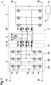
- FIG. 1 discloses a DC/DC-converter 1 according to a first embodiment of the invention.
- the DC/DC-converter 1 comprises a transformer 2, a first converter circuit 6, a second converter circuit 7, a first resonance inductor circuit 15 and a control circuit 10.
- the DC/DC-converter 1 is designed for always working in a forward mode.
- the three primary coils 3a, 3b, 3c comprise a first primary side 3a, a second primary coil 3b and a third primary coil 3c.
- the three secondary coils 4a, 4b, 4c comprise a first secondary side 4a, a second secondary coil 4b and a third secondary coil 4c.
- the primary coils 3a, 3b, 3c are connected to the secondary coils 4a, 4b, 4c by a core of the transformer 2.
- the first resonance inductor circuit 15 comprises a first resonance inductance 15a, a second resonance inductance 15b and a third resonance inductance 15c.
- the first converter circuit 6 is a flying capacitor multilevel converter and is working as a DC/AC-converter in the forward mode.
- the first converter circuit 6 comprises two primary side contacts 8a, 8b, comprising a first primary side contact 8a and a second primary side contact 8b.
- the first converter circuit 6 is configured to receive a DC current on the two primary side contacts 8a, 8b and two convert the DC current into an alternating current having three phases.
- the first converter circuit 6 and therefore the flying capacitor multilevel converter comprises three legs 13a, 13b, 13c, wherein each leg is for creating one face of the three phases of the alternating current.
- the first leg 13a is connected to the first resonance inductance 15a.
- the first phase of the alternating current is provided to the first primary coil 3a via the first resonance inductance 15a.
- the second leg 13b is connected to the second resonance inductance 15b.
- the second phase of the alternating current is provided to the second primary coil 3b via the second resonance inductance 15b.
- the third leg 13c is connected to the third resonance inductance 15c.
- the third phase of the alternating current is provided to the third primary coil 3c via the third resonance inductance 15c.
- the primary side 2a of the transformer 2 is terminated by a number of three primary capacitors 5a, 5b, 5c, which are connected in a first polygon arrangement 5.
- the first polygon arrangement 5 is a first resonance capacitor circuit.
- the first polygon arrangement 5 is a closed ring circuit in which the three primary capacitors 5a, 5b, 5c are connected in series.
- the first primary capacitor 5a has one side that is connected to the first primary coil 3a and another side that is connected to the second primary coil 3b.
- the second primary capacitor 5b has one side that is connected to the first primary coil 3a and another side that is connected to the third primary coil 3c.
- the third primary capacitor 5c has one side that is connected to the second primary coil 3b and another side that is connected to the third primary coil 3c.
- the output side of each one of the primary capacitors 5a, 5b, 5c is connected to an input side of a following one of the primary capacitors 5a, 5b, 5c, such that all primary capacitors 5a, 5b, 5c are connected to a or polygon shape.
- the first polygon arrangement is a delta connection of the primary capacitors 5a, 5b, 5c.
- the primary capacitors 5a, 5b, 5c of the first polygon arrangement 5, as a first resonance capacitor circuit is forming a resonance circuit in combination with the resonance inductances 15a, 15b, 15c of the first resonance inductor circuit 15.
- the flying capacitor multilevel converter comprises the three legs 13a, 13b, 13c, each leg for generating one face of the alternating current that is provided to the primary coils 3a, 3b, 3c.
- the first leg 13a is also depicted in figure 7 .
- a central point 17 of the first leg is connected to the first resonance inductor circuit 15, in particular to the first resonance inductance 15a.
- the central point 17 is connected via two serially connected transistors 14, that is a first transistor 14a and a second transistor 14b, to the first primary side contact 8a.
- the central point 17 is further connected via two serially connected transistors 14, that is a third transistor 14c and a four transistor 14d, to the second primary side contact 8b.
- the transistors are all connected in series in between the first primary side contact 8a and the second primary side contact 8b, wherein the switchable contacts of the transistors 14 are used for the serial connection.
- a bridge comprising a multilevel capacitor 18 is connected on one side in between the first transistor 14a and the second transistor 14b and is connected on the other side in between the third transistor 14c and the fourth transistor 14d.
- the transistors 14 can be switched as commonly performed in flying capacitor multilevel converters, wherein the switching process is controlled by the control circuit 10.
- the second leg 14b and the third leg 13c have the same layout as the first leg 13a.
- the control circuit 10 can utilize any known switching scheme for switching the transistors 14 of the flying capacitor multilevel converter. Such switching scheme is to be selected to ensure that corresponding capacitors in the same leg 13a, 13b, 13c are not switched on at the same time. For example, referring to the exemplary first leg 13a as depicted in figure 7 , it is to be avoided that the first transistor 14a is switch on simultaneously with the fourth transistor 14d and that that the second transistor 14b is switch on simultaneously with the third transistor 14c.
- either the voltage that is applied to the first primary side contact 8a, the voltage that is applied to the second primary side contact 8b or a voltage that is half a voltage difference between the voltage of the first primary side contact 8a and the second primary side contact 8b can be switched to the central point 17. This way, the voltage drop over each transistor 14 is reduced and different voltage levels can be provided to the connected primary coil.
- each leg 13a, 13b, 13c comprises a higher number of transistors 14. This is depicted on the right side in figure 7 .
- a number of m transistors is connected in between the central point 17 and each one of the primary side contact 8a, 8b.
- additional bridges each bridge comprising a multilevel capacitor 18, are provided.
- Each bridge comprises one side that is connected between two pairs of the transistors 14 on the leg towards the first primary side contact 8a and one side that is connected between two pairs of the transistors on the leg towards the second primary side contact 8b.
- the first leg 13a, 13b 13c of the first multilevel converter comprises a first half-leg 21 and a second half-leg 22, as exemplary depicted in figure 7 , wherein a number of m of the electrical switches, that is the transistors 14, is connected in series in each half-leg 21, 22.
- the first half-leg 21 and the second half-leg 22 are connected by one or more bridges 20, each bridge 20 comprising a multilevel capacitor 18, wherein one side of the bridge 20 is connected in between two subsequent electrical switches 14a, 14b of the first half-leg and the other side of the bridge is connected in between two corresponding subsequent transistors 14c, 14d of the second half-leg 22.
- the switching of the transistors 14 is controlled in a way that a voltage drop of U dc /m is achieved over each multilevel capacitor 18, wherein U dc is the voltage that is supplied to the primary side contacts 8a, 8b.
- each of the legs 13a, 13b 13c is capable to provide different voltage levels to the respective primary coil 3a, 3b, 3c for providing the alternating current.
- the number of voltage levels is dependent on the number of transistors 14 that are connected in series per leg.
- the second converter circuit seven can be any type of rectifier.
- the second converter circuit 7 can be an active rectifier.
- each one of the secondary coils 4a, 4b, 4c is connected via one transistor to a first secondary side contact 9a and is connected via one transistor to a second secondary side contact 9b.
- the transistors of the second converter circuit are controlled by the control circuit 10 to convert the alternating current that is induced to the secondary coils 4a, 4b, 4c to a direct current that is provided to the secondary side contacts 9a, 9b.
- the first converter circuit 6 is connected in between the primary side 2a of the transformer 2 and the two primary side contacts 8a, 8b.
- the first converter circuit 6 comprises a multilevel converter, that is configured to work as a inverter when the DC/DC-converter 1 is used in a forward mode, wherein the multilevel converter is configured to receive the DC input current that is provided to the primary side contacts 8a, 8b and to provide three phases of the alternating current to the three primary coils 3a, 3b, 3c of the transformer 2, respectively.
- the second converter circuit 7 is connected in between the secondary side 2b of the transformer 2 and the two secondary side contacts 9a, 9b and is configured to work as a rectifier when the DC/DC-converter 1 is used in the forward mode, wherein the second converter circuit 7 is configured to receive the induced alternating current from each of the three secondary coils 4a, 4b, 4c of the transformer 2, and to provide a DC output current to the secondary side contacts 9a, 9b.
- number describes the number of legs 13a, 13b, 13c of the multilevel converter, the number of primary coils 3a, 3b 3c, the number of secondary coils 4a, 4b, 4c, the number of primary capacitors 5a, 5b, 5c and a number of legs of the second converter circuit 7.
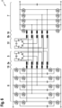
- a second embodiment is depicted in figure 2 .
- the embodiment essentially corresponds to the first embodiment.
- the number of n is set to be greater than three.
- the DC/DC-converter 1 comprises a first converter circuit 6 that comprises four legs 13a, 13b, 13c, 13d, a transformer 2 that comprises four primary coils 3a, 3b 3c, 3d and four secondary coils 4a, 4b, 4c, 4d, a first polygon arrangement 5 that comprises four primary capacitors 5a, 5b, 5c, 5d and the second converter circuit 7 comprises four legs.
- a fourth leg 13d is added to the first converter circuit 6, wherein the fourth leg 13d has the same layout as each one of the first to third leg 13a, 13b, 13c.
- the fourth leg 13d is providing a fourth phase of the alternating current to the fourth primary coil 4d.
- the primary coils 4a, 4b, 4c, 4d are terminated by the first polygon arrangement 5, wherein the additional fourth primary capacitor 5d is added to the ring of primary capacitors 5a, 5b, 5c, 5d.
- a third embodiment is depicted in figure 3 .
- the embodiment essentially corresponds to the first and second embodiment.
- the number of n is set to be greater than four.
- a DC/DC-converter 1 according to a fourth embodiment of the invention is depicted in figure 4 .
- the DC/DC-converter 1 according to a fourth embodiment essentially corresponds to the DC/DC-converter 1 according to a first embodiment.
- the DC/DC-converter 1 according to the fourth embodiment is capable to work either in a forward mode or in a backward mode.
- the control circuit 10 is capable to select whether the DC/DC-converter 1 is driven in the forward mode or in the backboard mode. According to the selection, the transistors of the first converter circuit 6 and the second converter circuit 7 are switched accordingly by the control circuit 10.
- the control circuit 10 controls the first converter circuit 6 to work as an inverter and to control the second converter circuit 7 to work as a rectifier. Therefore, the DC/DC-converter 1 is operated in a same way as the circuit that is described with figure 1 .
- the control circuit 10 controls the first converter circuit 6 to work as a rectifier and controls the second converter circuit 7 to work as an inverter.
- a DC current that is provided as an input current to the primary side contacts 8a, 8b is converted to a different DC current that is provided as an output current to the secondary side contacts 9a, 9b.
- a DC current that is provided as an input current to the secondary side contacts 9a, 9b is converted to a different DC current that is provided as an output current to the primary side contacts 8a, 8b.ln an example, this allows that the DC/DC-converter 1 can be used to connect a chargeable battery to the secondary side contacts 9a, 9b. The battery can then be charged in the forward mode and can be discharged in the backward mode.
- the secondary coils 4a, 4b, 4c are terminated by a second polygon arrangement 12.
- the second polygon arrangement 12 is a second resonance capacitor circuit.
- the second polygon arrangement 12 consists of a first secondary capacitor 12a, a second secondary capacitor 12b and a third secondary capacitor 12c.
- the second polygon arrangement 12 corresponds to the first polygon arrangement 5 but is terminating the secondary coils 4a, 4b, 4c instead of the primary coils 3a, 3b, 3c. Therefore, the secondary side 2b of the transformer 2 is terminated by a number of n secondary capacitors 12a, 12b, 12c, which are connected in a second polygon arrangement, each of the capacitors connecting two of the secondary coils 4a, 4b, 4c.
- the DC/DC-converter 1 optionally comprises a second resonance inductor circuit 16.
- the second resonance inductor circuit 16 comprises a first resonance inductance 16a, a second resonance inductance 16b, and a third resonance inductance 16c.
- One leg of the second converter circuit 7 is connected via the first resonance inductance 16a of the second resonance inductor circuit 16 to the first secondary coil 4a.
- Another leg of the second converter circuit 7 is connected via the second resonance inductance 16b of the second resonance inductor circuit 16 to the second secondary coil 4b.
- Another leg of the second converter circuit 7 is connected via the third resonance inductance 16c of the second resonance inductor circuit 16 to the third secondary coil 4c.
- the secondary capacitors 12a, 12b, 12c of the second polygon arrangement 12, as a second resonance capacitor circuit is forming a resonance circuit in combination with the resonance inductances 16a, 16b, 16c of the second resonance inductor circuit 16.
- the multilevel converter of the first converter circuit 6 is controlled by the control circuit 10 to work as a rectifier.
- the flying capacitor multilevel converter is receiving an alternating current from each the n primary coils 3a, 3b, 3c of the transformer 2 and generates an DC output current at the primary side contacts 8a, 8b.
- the second converter circuit 7 is controlled by the control circuit 10 to work as a inverter.
- the second converter circuit 7 is receiving a DC input current from the secondary side contacts 9a, 9b and is generating an alternating current at the n secondary coils 4a, 4b, 4c of the transformer 2.
- circuits of figure 2 correspond to the circuits of figure 1 , wherein the second polygon arrangement 12 and the second resonance inductor circuit 16 have been added to the secondary side 2b of the transformer 2, which is to improve the signal shape of the alternating current that is generated by the second converter circuit 7 in the backboard mode.
- the DC/DC-converters of Figures 1 to 3 can be extended to work in the backward mode by adding the second polygon arrangement 12 and the second resonance inductor circuit 16.
- the second converter circuit 7 can comprises a multilevel converter, wherein the multilevel converter is in particular a flying capacitor multilevel converter.
- the design of the multilevel converter of the first converter circuit 6 can also be applied to the second converter circuit 7.
- the number of transistors per leg of the multilevel converter in the first converter circuit 6 or the second converter circuit 7 can be set to a number of 2*m, wherein the number of m can be set to any value equal or larger than 2.
Landscapes
- Engineering & Computer Science (AREA)
- Power Engineering (AREA)
- Dc-Dc Converters (AREA)
- Inverter Devices (AREA)
Priority Applications (4)
| Application Number | Priority Date | Filing Date | Title |
|---|---|---|---|
| EP22161979.4A EP4246787A1 (de) | 2022-03-14 | 2022-03-14 | Dc/dc wandler mit mehrstufiger technologie |
| CN202310230324.3A CN116760296A (zh) | 2022-03-14 | 2023-03-10 | 使用多电平技术的dc/dc变换器 |
| US18/183,181 US12463542B2 (en) | 2022-03-14 | 2023-03-14 | DC/DC-converter using multilevel technology |
| US19/353,611 US20260039213A1 (en) | 2022-03-14 | 2025-10-09 | Dc/dc-converter using multilevel technology |
Applications Claiming Priority (1)
| Application Number | Priority Date | Filing Date | Title |
|---|---|---|---|
| EP22161979.4A EP4246787A1 (de) | 2022-03-14 | 2022-03-14 | Dc/dc wandler mit mehrstufiger technologie |
Publications (1)
| Publication Number | Publication Date |
|---|---|
| EP4246787A1 true EP4246787A1 (de) | 2023-09-20 |
Family
ID=80775333
Family Applications (1)
| Application Number | Title | Priority Date | Filing Date |
|---|---|---|---|
| EP22161979.4A Pending EP4246787A1 (de) | 2022-03-14 | 2022-03-14 | Dc/dc wandler mit mehrstufiger technologie |
Country Status (3)
| Country | Link |
|---|---|
| US (2) | US12463542B2 (de) |
| EP (1) | EP4246787A1 (de) |
| CN (1) | CN116760296A (de) |
Cited By (2)
| Publication number | Priority date | Publication date | Assignee | Title |
|---|---|---|---|---|
| EP4672577A1 (de) | 2024-06-27 | 2025-12-31 | Delta Electronics (Thailand) Public Co., Ltd. | Mehrpegel- und mehrphasenwandler und steuerungsverfahren zum betreiben eines mehrpegel- und mehrphasenwandlers |
| DE102025131312A1 (de) * | 2024-08-06 | 2026-02-12 | Tq-Systems Gmbh | Mehrstufiger DC-DC-Converter mit Flying-Capacitor-Multilevel-Halbbrücke und Gleichrichterbaugruppe |
Families Citing this family (1)
| Publication number | Priority date | Publication date | Assignee | Title |
|---|---|---|---|---|
| EP4422051A1 (de) * | 2023-02-22 | 2024-08-28 | Delta Electronics (Thailand) Public Co., Ltd. | Mehrphasige gleichstromwandlerschaltung |
Citations (3)
| Publication number | Priority date | Publication date | Assignee | Title |
|---|---|---|---|---|
| US20150180350A1 (en) * | 2013-12-20 | 2015-06-25 | Huawei Technologies Co., Ltd. | Resonant bidirectional converter, uninterruptible power supply apparatus, and control method |
| US20190379291A1 (en) * | 2018-06-12 | 2019-12-12 | Virginia Tech Intellectual Properties, Inc | Bidirectional three-phase direct current (dc)/dc converters |
| US20190379292A1 (en) * | 2018-06-12 | 2019-12-12 | Virginia Tech Intellectual Properties, Inc. | Interleaved converters with integrated magnetics |
Family Cites Families (32)
| Publication number | Priority date | Publication date | Assignee | Title |
|---|---|---|---|---|
| US7372709B2 (en) * | 2003-09-11 | 2008-05-13 | The Board Of Trustees Of The University Of Illinois | Power conditioning system for energy sources |
| US20070230226A1 (en) * | 2003-11-25 | 2007-10-04 | Jih-Sheng Lai | Multilevel intelligent universal auto-transformer |
| JP5532192B2 (ja) * | 2008-01-24 | 2014-06-25 | 独立行政法人産業技術総合研究所 | 電力変換装置 |
| GB2476278A (en) * | 2009-12-17 | 2011-06-22 | Eltek Valere As | Resonant circuit with transformer having three sets of windings |
| DE102012005974A1 (de) * | 2012-03-23 | 2013-09-26 | Tq-Systems Gmbh | Elektrische Schaltung und Verfahren zu deren Betrieb |
| EP2897277A4 (de) * | 2012-09-13 | 2016-05-25 | Nat Inst Of Advanced Ind Scien | Mehrstufige stromwandlungsschaltung und vorrichtung damit |
| US9941813B2 (en) * | 2013-03-14 | 2018-04-10 | Solaredge Technologies Ltd. | High frequency multi-level inverter |
| CN103595367B (zh) * | 2013-11-07 | 2017-03-08 | 华为技术有限公司 | 一种磁集成器件及一种功率转换电路 |
| GB2528894B (en) * | 2014-08-01 | 2017-05-10 | Eisergy Ltd | Power factor correction stages in power conversion |
| CN108475999B (zh) * | 2016-03-17 | 2020-09-08 | 汪洪亮 | 单相五电平有源嵌位变换器单元及变换器 |
| CN109874380A (zh) * | 2016-07-07 | 2019-06-11 | 华为技术有限公司 | 四开关三相dc-dc谐振转换器 |
| EP3314740B1 (de) * | 2016-07-07 | 2020-05-27 | Huawei Technologies Co., Ltd. | Dreiphasiger gleichstromresonanzwandler mit zwei trafos |
| CN108258909A (zh) * | 2017-12-22 | 2018-07-06 | 华为技术有限公司 | 谐振变换电路及其控制方法 |
| US11491883B2 (en) * | 2018-04-10 | 2022-11-08 | University Of Maryland, College Park | Vehicle on-board charger for bi-directional charging of low/high voltage batteries |
| CN110417267A (zh) * | 2018-04-26 | 2019-11-05 | 比亚迪股份有限公司 | Dcdc变换器、车载充电机和电动车辆 |
| CN110417266A (zh) * | 2018-04-26 | 2019-11-05 | 比亚迪股份有限公司 | Dcdc变换器、车载充电机和电动车辆 |
| US10790081B2 (en) * | 2018-05-21 | 2020-09-29 | Virginia Tech Intellectual Properties, Inc. | Interleaved converters with integrated magnetics |
| JP7270139B2 (ja) * | 2019-08-21 | 2023-05-10 | パナソニックIpマネジメント株式会社 | Dc/dc変換装置 |
| EP3796528B1 (de) * | 2019-09-20 | 2023-12-27 | ABB Schweiz AG | Stromausgleich in leistungshalbleitern eines gleichstromwandlers |
| US11418125B2 (en) * | 2019-10-25 | 2022-08-16 | The Research Foundation For The State University Of New York | Three phase bidirectional AC-DC converter with bipolar voltage fed resonant stages |
| KR20220093328A (ko) * | 2019-11-06 | 2022-07-05 | 이피션트 파워 컨버젼 코퍼레이션 | 플라잉 캐패시터를 프리차징하기 위한 전압 분배기를 갖춘 멀티 레벨 컨버터 |
| US11088625B1 (en) * | 2020-05-26 | 2021-08-10 | Institute Of Electrical Engineering, Chinese Academy Of Sciences | Three-phase CLLC bidirectional DC-DC converter and a method for controlling the same |
| CN113949272B (zh) * | 2020-06-30 | 2025-08-08 | 台达电子工业股份有限公司 | Dc-dc谐振转换器及其控制方法 |
| US11404966B2 (en) * | 2020-07-02 | 2022-08-02 | Delta Electronics, Inc. | Isolated multi-phase DC/DC converter with reduced quantity of blocking capacitors |
| US12046997B2 (en) * | 2020-07-13 | 2024-07-23 | Delta Electronics, Inc. | Isolated resonant converter and control method thereof |
| NL2026176B1 (en) * | 2020-07-30 | 2022-04-04 | Prodrive Tech Innovation Services B V | Multi-level bidirectional electrical AC/DC converter |
| US11689115B2 (en) * | 2020-10-02 | 2023-06-27 | The Research Foundation for the State University o | Bidirectional AC-DC converter with multilevel power factor correction |
| CN112636613B (zh) * | 2020-12-16 | 2022-09-16 | 矽力杰半导体技术(杭州)有限公司 | 交流-直流转换电路 |
| WO2022128134A1 (en) * | 2020-12-18 | 2022-06-23 | Huawei Technologies Co., Ltd. | Method for operating a converter, control unit for performing the method and converter |
| US12027986B2 (en) * | 2021-01-08 | 2024-07-02 | Ford Global Technologies, Llc | Magnetic integration of three-phase resonant converter and accessory power supply |
| CN115589149A (zh) * | 2021-07-06 | 2023-01-10 | 光宝电子(广州)有限公司 | 三相交错谐振变换器和电源电路 |
| EP4138287A1 (de) * | 2021-08-17 | 2023-02-22 | ABB E-mobility B.V. | Weichschaltender modulator für mehrpunkt umrichter mit fliegenden kondensatoren |
-
2022
- 2022-03-14 EP EP22161979.4A patent/EP4246787A1/de active Pending
-
2023
- 2023-03-10 CN CN202310230324.3A patent/CN116760296A/zh active Pending
- 2023-03-14 US US18/183,181 patent/US12463542B2/en active Active
-
2025
- 2025-10-09 US US19/353,611 patent/US20260039213A1/en active Pending
Patent Citations (3)
| Publication number | Priority date | Publication date | Assignee | Title |
|---|---|---|---|---|
| US20150180350A1 (en) * | 2013-12-20 | 2015-06-25 | Huawei Technologies Co., Ltd. | Resonant bidirectional converter, uninterruptible power supply apparatus, and control method |
| US20190379291A1 (en) * | 2018-06-12 | 2019-12-12 | Virginia Tech Intellectual Properties, Inc | Bidirectional three-phase direct current (dc)/dc converters |
| US20190379292A1 (en) * | 2018-06-12 | 2019-12-12 | Virginia Tech Intellectual Properties, Inc. | Interleaved converters with integrated magnetics |
Non-Patent Citations (2)
| Title |
|---|
| GADELRAB RIMON ET AL: "Three-Phase Interleaved LLC Resonant Converter with Integrated Planar Magnetics for Telecom and Server Application", 2020 IEEE APPLIED POWER ELECTRONICS CONFERENCE AND EXPOSITION (APEC), IEEE, 15 March 2020 (2020-03-15), pages 512 - 519, XP033784885, DOI: 10.1109/APEC39645.2020.9124392 * |
| NUNEZ JUAN IGNACIO ET AL: "Three-phase CLLLC Resonant Converters", 2021 IEEE 15TH INTERNATIONAL CONFERENCE ON COMPATIBILITY, POWER ELECTRONICS AND POWER ENGINEERING (CPE-POWERENG), IEEE, 14 July 2021 (2021-07-14), pages 1 - 6, XP033956737, DOI: 10.1109/CPE-POWERENG50821.2021.9501219 * |
Cited By (2)
| Publication number | Priority date | Publication date | Assignee | Title |
|---|---|---|---|---|
| EP4672577A1 (de) | 2024-06-27 | 2025-12-31 | Delta Electronics (Thailand) Public Co., Ltd. | Mehrpegel- und mehrphasenwandler und steuerungsverfahren zum betreiben eines mehrpegel- und mehrphasenwandlers |
| DE102025131312A1 (de) * | 2024-08-06 | 2026-02-12 | Tq-Systems Gmbh | Mehrstufiger DC-DC-Converter mit Flying-Capacitor-Multilevel-Halbbrücke und Gleichrichterbaugruppe |
Also Published As
| Publication number | Publication date |
|---|---|
| US12463542B2 (en) | 2025-11-04 |
| CN116760296A (zh) | 2023-09-15 |
| US20260039213A1 (en) | 2026-02-05 |
| US20230291320A1 (en) | 2023-09-14 |
Similar Documents
| Publication | Publication Date | Title |
|---|---|---|
| US12463542B2 (en) | DC/DC-converter using multilevel technology | |
| US11677308B2 (en) | Multi-phase converter topology for multi-phase and single-phase operation | |
| EP3753098B1 (de) | Leistungswandler mit grossem gleichspannungsbereich | |
| US6014323A (en) | Multiphase power converter | |
| EP3223419B1 (de) | Direkte wechselstrom-wechselstrom-wandleranordnung und wandlersystem damit | |
| JP4695138B2 (ja) | 低高調波多相コンバータ回路 | |
| JP2011072076A (ja) | 直流変換装置 | |
| CN106031012A (zh) | 用于ac系统的转换器 | |
| CA2696215C (en) | Medium voltage inverter system | |
| US10340804B2 (en) | Power supply circuit including converter and power supply system using the same | |
| EP4383546A1 (de) | Stromversorgungsvorrichtung, dreiphasentransformatorschaltung und ladesäule | |
| EP3772170A1 (de) | Llc-umrichter mit mehreren wechselrichtern | |
| Feretti et al. | Family of non-isolated high step-up DC–DC converters based on the multi-state switching cell | |
| US11664721B2 (en) | Multiphase interleaved forward power converters including clamping circuits | |
| KR20190025196A (ko) | 절연형 dc-dc 컨버터 및 그 구동방법 | |
| US9379636B2 (en) | Current generator and method for generating current pulses | |
| US12334830B2 (en) | Multi-phase cascaded bridge for DC/DC, AC/DC, and DC/AC applications | |
| JP7230633B2 (ja) | 電力変換装置 | |
| KR101849001B1 (ko) | 고전압 대전류 전력 변환 장치 | |
| WO2024082211A1 (en) | Dc-to-dc power converter | |
| JP4150211B2 (ja) | 電力変換装置 | |
| US20260031735A1 (en) | Isolated DC/DC Power Converter | |
| WO2024124523A1 (en) | Voltage converters having wide output voltage ranges with improved voltage balance | |
| JP2019075915A (ja) | マルチレベル電力変換装置およびその制御方法 | |
| JP2008131756A (ja) | 電力変換装置 |
Legal Events
| Date | Code | Title | Description |
|---|---|---|---|
| PUAI | Public reference made under article 153(3) epc to a published international application that has entered the european phase |
Free format text: ORIGINAL CODE: 0009012 |
|
| STAA | Information on the status of an ep patent application or granted ep patent |
Free format text: STATUS: THE APPLICATION HAS BEEN PUBLISHED |
|
| AK | Designated contracting states |
Kind code of ref document: A1 Designated state(s): AL AT BE BG CH CY CZ DE DK EE ES FI FR GB GR HR HU IE IS IT LI LT LU LV MC MK MT NL NO PL PT RO RS SE SI SK SM TR |
|
| STAA | Information on the status of an ep patent application or granted ep patent |
Free format text: STATUS: REQUEST FOR EXAMINATION WAS MADE |
|
| 17P | Request for examination filed |
Effective date: 20240223 |
|
| RBV | Designated contracting states (corrected) |
Designated state(s): AL AT BE BG CH CY CZ DE DK EE ES FI FR GB GR HR HU IE IS IT LI LT LU LV MC MK MT NL NO PL PT RO RS SE SI SK SM TR |
|
| STAA | Information on the status of an ep patent application or granted ep patent |
Free format text: STATUS: EXAMINATION IS IN PROGRESS |
|
| 17Q | First examination report despatched |
Effective date: 20250428 |