EP4422051A1 - Mehrphasige gleichstromwandlerschaltung - Google Patents
Mehrphasige gleichstromwandlerschaltung Download PDFInfo
- Publication number
- EP4422051A1 EP4422051A1 EP23157968.1A EP23157968A EP4422051A1 EP 4422051 A1 EP4422051 A1 EP 4422051A1 EP 23157968 A EP23157968 A EP 23157968A EP 4422051 A1 EP4422051 A1 EP 4422051A1
- Authority
- EP
- European Patent Office
- Prior art keywords
- secondary side
- converter
- phase
- transformer
- resonant capacitor
- Prior art date
- Legal status (The legal status is an assumption and is not a legal conclusion. Google has not performed a legal analysis and makes no representation as to the accuracy of the status listed.)
- Pending
Links
Images




Classifications
-
- H—ELECTRICITY
- H02—GENERATION; CONVERSION OR DISTRIBUTION OF ELECTRIC POWER
- H02M—APPARATUS FOR CONVERSION BETWEEN AC AND AC, BETWEEN AC AND DC, OR BETWEEN DC AND DC, AND FOR USE WITH MAINS OR SIMILAR POWER SUPPLY SYSTEMS; CONVERSION OF DC OR AC INPUT POWER INTO SURGE OUTPUT POWER; CONTROL OR REGULATION THEREOF
- H02M3/00—Conversion of DC power input into DC power output
- H02M3/003—Constructional details, e.g. physical layout, assembly, wiring or busbar connections
-
- H—ELECTRICITY
- H02—GENERATION; CONVERSION OR DISTRIBUTION OF ELECTRIC POWER
- H02M—APPARATUS FOR CONVERSION BETWEEN AC AND AC, BETWEEN AC AND DC, OR BETWEEN DC AND DC, AND FOR USE WITH MAINS OR SIMILAR POWER SUPPLY SYSTEMS; CONVERSION OF DC OR AC INPUT POWER INTO SURGE OUTPUT POWER; CONTROL OR REGULATION THEREOF
- H02M3/00—Conversion of DC power input into DC power output
- H02M3/22—Conversion of DC power input into DC power output with intermediate conversion into AC
- H02M3/24—Conversion of DC power input into DC power output with intermediate conversion into AC by static converters
- H02M3/28—Conversion of DC power input into DC power output with intermediate conversion into AC by static converters using discharge tubes with control electrode or semiconductor devices with control electrode to produce the intermediate AC
- H02M3/325—Conversion of DC power input into DC power output with intermediate conversion into AC by static converters using discharge tubes with control electrode or semiconductor devices with control electrode to produce the intermediate AC using devices of a triode or a transistor type requiring continuous application of a control signal
- H02M3/335—Conversion of DC power input into DC power output with intermediate conversion into AC by static converters using discharge tubes with control electrode or semiconductor devices with control electrode to produce the intermediate AC using devices of a triode or a transistor type requiring continuous application of a control signal using semiconductor devices only
- H02M3/3353—Conversion of DC power input into DC power output with intermediate conversion into AC by static converters using discharge tubes with control electrode or semiconductor devices with control electrode to produce the intermediate AC using devices of a triode or a transistor type requiring continuous application of a control signal using semiconductor devices only having at least two simultaneously operating switches on the input side, e.g. "double forward" or "double (switched) flyback" converter
-
- H—ELECTRICITY
- H01—ELECTRIC ELEMENTS
- H01F—MAGNETS; INDUCTANCES; TRANSFORMERS; SELECTION OF MATERIALS FOR THEIR MAGNETIC PROPERTIES
- H01F27/00—Details of transformers or inductances, in general
- H01F27/34—Special means for preventing or reducing unwanted electric or magnetic effects, e.g. no-load losses, reactive currents, harmonics, oscillations, leakage fields
- H01F27/38—Auxiliary core members; Auxiliary coils or windings
-
- H—ELECTRICITY
- H01—ELECTRIC ELEMENTS
- H01F—MAGNETS; INDUCTANCES; TRANSFORMERS; SELECTION OF MATERIALS FOR THEIR MAGNETIC PROPERTIES
- H01F27/00—Details of transformers or inductances, in general
- H01F27/40—Structural association with built-in electric component, e.g. fuse
-
- H—ELECTRICITY
- H02—GENERATION; CONVERSION OR DISTRIBUTION OF ELECTRIC POWER
- H02M—APPARATUS FOR CONVERSION BETWEEN AC AND AC, BETWEEN AC AND DC, OR BETWEEN DC AND DC, AND FOR USE WITH MAINS OR SIMILAR POWER SUPPLY SYSTEMS; CONVERSION OF DC OR AC INPUT POWER INTO SURGE OUTPUT POWER; CONTROL OR REGULATION THEREOF
- H02M3/00—Conversion of DC power input into DC power output
- H02M3/01—Resonant DC/DC converters
-
- H—ELECTRICITY
- H02—GENERATION; CONVERSION OR DISTRIBUTION OF ELECTRIC POWER
- H02M—APPARATUS FOR CONVERSION BETWEEN AC AND AC, BETWEEN AC AND DC, OR BETWEEN DC AND DC, AND FOR USE WITH MAINS OR SIMILAR POWER SUPPLY SYSTEMS; CONVERSION OF DC OR AC INPUT POWER INTO SURGE OUTPUT POWER; CONTROL OR REGULATION THEREOF
- H02M3/00—Conversion of DC power input into DC power output
- H02M3/01—Resonant DC/DC converters
- H02M3/015—Resonant DC/DC converters with means for adaptation of resonance frequency, e.g. by modification of capacitance or inductance of resonance circuit
-
- H—ELECTRICITY
- H02—GENERATION; CONVERSION OR DISTRIBUTION OF ELECTRIC POWER
- H02M—APPARATUS FOR CONVERSION BETWEEN AC AND AC, BETWEEN AC AND DC, OR BETWEEN DC AND DC, AND FOR USE WITH MAINS OR SIMILAR POWER SUPPLY SYSTEMS; CONVERSION OF DC OR AC INPUT POWER INTO SURGE OUTPUT POWER; CONTROL OR REGULATION THEREOF
- H02M3/00—Conversion of DC power input into DC power output
- H02M3/22—Conversion of DC power input into DC power output with intermediate conversion into AC
- H02M3/24—Conversion of DC power input into DC power output with intermediate conversion into AC by static converters
- H02M3/28—Conversion of DC power input into DC power output with intermediate conversion into AC by static converters using discharge tubes with control electrode or semiconductor devices with control electrode to produce the intermediate AC
- H02M3/325—Conversion of DC power input into DC power output with intermediate conversion into AC by static converters using discharge tubes with control electrode or semiconductor devices with control electrode to produce the intermediate AC using devices of a triode or a transistor type requiring continuous application of a control signal
- H02M3/335—Conversion of DC power input into DC power output with intermediate conversion into AC by static converters using discharge tubes with control electrode or semiconductor devices with control electrode to produce the intermediate AC using devices of a triode or a transistor type requiring continuous application of a control signal using semiconductor devices only
- H02M3/33569—Conversion of DC power input into DC power output with intermediate conversion into AC by static converters using discharge tubes with control electrode or semiconductor devices with control electrode to produce the intermediate AC using devices of a triode or a transistor type requiring continuous application of a control signal using semiconductor devices only having several active switching elements
- H02M3/33571—Half-bridge at primary side of an isolation transformer
-
- H—ELECTRICITY
- H02—GENERATION; CONVERSION OR DISTRIBUTION OF ELECTRIC POWER
- H02M—APPARATUS FOR CONVERSION BETWEEN AC AND AC, BETWEEN AC AND DC, OR BETWEEN DC AND DC, AND FOR USE WITH MAINS OR SIMILAR POWER SUPPLY SYSTEMS; CONVERSION OF DC OR AC INPUT POWER INTO SURGE OUTPUT POWER; CONTROL OR REGULATION THEREOF
- H02M3/00—Conversion of DC power input into DC power output
- H02M3/22—Conversion of DC power input into DC power output with intermediate conversion into AC
- H02M3/24—Conversion of DC power input into DC power output with intermediate conversion into AC by static converters
- H02M3/28—Conversion of DC power input into DC power output with intermediate conversion into AC by static converters using discharge tubes with control electrode or semiconductor devices with control electrode to produce the intermediate AC
- H02M3/325—Conversion of DC power input into DC power output with intermediate conversion into AC by static converters using discharge tubes with control electrode or semiconductor devices with control electrode to produce the intermediate AC using devices of a triode or a transistor type requiring continuous application of a control signal
- H02M3/335—Conversion of DC power input into DC power output with intermediate conversion into AC by static converters using discharge tubes with control electrode or semiconductor devices with control electrode to produce the intermediate AC using devices of a triode or a transistor type requiring continuous application of a control signal using semiconductor devices only
- H02M3/33569—Conversion of DC power input into DC power output with intermediate conversion into AC by static converters using discharge tubes with control electrode or semiconductor devices with control electrode to produce the intermediate AC using devices of a triode or a transistor type requiring continuous application of a control signal using semiconductor devices only having several active switching elements
- H02M3/33573—Full-bridge at primary side of an isolation transformer
-
- H—ELECTRICITY
- H02—GENERATION; CONVERSION OR DISTRIBUTION OF ELECTRIC POWER
- H02M—APPARATUS FOR CONVERSION BETWEEN AC AND AC, BETWEEN AC AND DC, OR BETWEEN DC AND DC, AND FOR USE WITH MAINS OR SIMILAR POWER SUPPLY SYSTEMS; CONVERSION OF DC OR AC INPUT POWER INTO SURGE OUTPUT POWER; CONTROL OR REGULATION THEREOF
- H02M3/00—Conversion of DC power input into DC power output
- H02M3/22—Conversion of DC power input into DC power output with intermediate conversion into AC
- H02M3/24—Conversion of DC power input into DC power output with intermediate conversion into AC by static converters
- H02M3/28—Conversion of DC power input into DC power output with intermediate conversion into AC by static converters using discharge tubes with control electrode or semiconductor devices with control electrode to produce the intermediate AC
- H02M3/325—Conversion of DC power input into DC power output with intermediate conversion into AC by static converters using discharge tubes with control electrode or semiconductor devices with control electrode to produce the intermediate AC using devices of a triode or a transistor type requiring continuous application of a control signal
- H02M3/335—Conversion of DC power input into DC power output with intermediate conversion into AC by static converters using discharge tubes with control electrode or semiconductor devices with control electrode to produce the intermediate AC using devices of a triode or a transistor type requiring continuous application of a control signal using semiconductor devices only
- H02M3/33569—Conversion of DC power input into DC power output with intermediate conversion into AC by static converters using discharge tubes with control electrode or semiconductor devices with control electrode to produce the intermediate AC using devices of a triode or a transistor type requiring continuous application of a control signal using semiconductor devices only having several active switching elements
- H02M3/33576—Conversion of DC power input into DC power output with intermediate conversion into AC by static converters using discharge tubes with control electrode or semiconductor devices with control electrode to produce the intermediate AC using devices of a triode or a transistor type requiring continuous application of a control signal using semiconductor devices only having several active switching elements having at least one active switching element at the secondary side of an isolation transformer
- H02M3/33584—Bidirectional converters
-
- H—ELECTRICITY
- H02—GENERATION; CONVERSION OR DISTRIBUTION OF ELECTRIC POWER
- H02M—APPARATUS FOR CONVERSION BETWEEN AC AND AC, BETWEEN AC AND DC, OR BETWEEN DC AND DC, AND FOR USE WITH MAINS OR SIMILAR POWER SUPPLY SYSTEMS; CONVERSION OF DC OR AC INPUT POWER INTO SURGE OUTPUT POWER; CONTROL OR REGULATION THEREOF
- H02M7/00—Conversion of AC power input into DC power output; Conversion of DC power input into AC power output
- H02M7/42—Conversion of DC power input into AC power output without possibility of reversal
- H02M7/44—Conversion of DC power input into AC power output without possibility of reversal by static converters
- H02M7/48—Conversion of DC power input into AC power output without possibility of reversal by static converters using discharge tubes with control electrode or semiconductor devices with control electrode
- H02M7/4815—Resonant converters
- H02M7/4818—Resonant converters with means for adaptation of resonance frequency, e.g. by modification of capacitance or inductance of resonance circuits
-
- H—ELECTRICITY
- H01—ELECTRIC ELEMENTS
- H01F—MAGNETS; INDUCTANCES; TRANSFORMERS; SELECTION OF MATERIALS FOR THEIR MAGNETIC PROPERTIES
- H01F27/00—Details of transformers or inductances, in general
- H01F27/28—Coils; Windings; Conductive connections
- H01F27/2804—Printed windings
- H01F2027/2819—Planar transformers with printed windings, e.g. surrounded by two cores and to be mounted on printed circuit
-
- Y—GENERAL TAGGING OF NEW TECHNOLOGICAL DEVELOPMENTS; GENERAL TAGGING OF CROSS-SECTIONAL TECHNOLOGIES SPANNING OVER SEVERAL SECTIONS OF THE IPC; TECHNICAL SUBJECTS COVERED BY FORMER USPC CROSS-REFERENCE ART COLLECTIONS [XRACs] AND DIGESTS
- Y02—TECHNOLOGIES OR APPLICATIONS FOR MITIGATION OR ADAPTATION AGAINST CLIMATE CHANGE
- Y02B—CLIMATE CHANGE MITIGATION TECHNOLOGIES RELATED TO BUILDINGS, e.g. HOUSING, HOUSE APPLIANCES OR RELATED END-USER APPLICATIONS
- Y02B70/00—Technologies for an efficient end-user side electric power management and consumption
- Y02B70/10—Technologies improving the efficiency by using switched-mode power supplies [SMPS], i.e. efficient power electronics conversion e.g. power factor correction or reduction of losses in power supplies or efficient standby modes
Definitions
- the present invention concerns a multi-phase DC/DC converter circuit.
- power converters especially DC/DC (direct current to direct current) power converters are known.
- DC/DC direct current to direct current
- transformer devices are known from for example US 11404967 B2 , WO 2011/074977 , US 11233462 B2 and JP 2021153382 .
- 1-phase LLC converters are used in applications of up to 11 kW of power rating for DC-DC power conversion.
- 3-phase LLC topologies have been used. These are commonly known as 3-phase unidirectional LLC or 3-phase bidirectional CLLLC topologies.
- transformer topologies have the following drawbacks. Firstly, winding losses thereof are proportional to a square of the current and winding resistance. Resistance of the winding is proportional to the frequency of operation. In order to reduce the size of such converters, operation frequency is commonly increased. However, increased frequency leads to increased resistance and thus to higher losses and heat. Due to efficiency requirements and thermal constraints, converters generally are designed to achieve a tradeoff between size (power density), efficiency and cost with respect to amount of semiconductor and magnetic materials. Therefore, commonly, smaller size and higher efficiency thereof are commonly not simultaneously possible.
- a voltage gain (ratio of output and input voltage) of the converter is dependent on an operating frequency thereof (gain curve).
- the gain curve of an LLC converter is fixed based on circuit parameters such as transformer turns ratio, resonant inductance, magnetizing inductance, and resonant capacitance.
- a battery voltage varies widely based on a state of charge of the battery.
- the converter operates in a frequency control mode with limited capability to meet wide voltage variation criteria of the battery and simultaneously reduce tradeoffs such as converter losses.
- Common 2-stage converters for overcoming such limitations are however costly and are also prone to high power losses.
- common LLC converters are operated at different operating frequencies so as to provide the necessary gain depending on for example a state of charge of batteries. With this, however, such converters are commonly operated not at or near resonant frequency, and are therefore prone to high losses.
- bidirectional and bidirectional 3-phase LLC topologies are known. Such bidirectional topologies are for example implemented in modern automotive battery charging applications, in which the automobiles batteries are also used for example in powering a home.
- a bidirectional LLC topology which has optimal gain characteristics and high efficiency for both current directions (i.e. charging and discharging, also referred to as "forward operation", “backward operation”).
- forward operation also referred to as "forward operation”
- backward operation also referred to as "forward operation”
- the charging of the batteries of the automobile makes up a high percentage of the use of the converter, whereas the use of the batteries for example in powering the home is not as common. Therefore, common bidirectional topologies tradeoff high efficiency charging for an expansion of use-cases in applications, even though such use cases and applications are not often employed over the lifetime of these devices.
- one object of the present invention is to provide a multi-phase DC/DC converter circuit which has a small size (high power density) and has reduced losses (higher efficiency). Furthermore, it is an object of the present invention to provide a multi-phase DC/DC converter circuit which can advantageously be operated at or near resonant frequency independent of voltage gain requirements. Furthermore, it is an object of the present invention to provide a multi-phase DC/DC converter circuit which provides high energy-efficiency for both unidirectional and bidirectional applications.
- the multi-phase DC/DC converter circuit comprises a primary side switching circuit comprising a plurality of primary side switching legs, wherein each primary side switching leg comprises two more switch elements. Further, the multi-phase DC/DC converter circuit comprises at least one secondary side rectifier circuit each comprising a plurality of secondary side rectifier legs, wherein each secondary side rectifier leg comprises two or more rectifier elements. Furthermore, the converter circuit comprises a transformer, wherein the transformer comprises a primary side connected to the primary side switching circuit and a secondary side connected to each of the at least one secondary side rectifier circuit. In addition, the converter circuit comprises at least one resonant capacitor network, each connected to the primary side or to the secondary side of the transformer, wherein each resonant capacitor network comprises a plurality of capacitors.
- each primary side switching leg comprises two switch elements.
- the switch elements are IGBTs or MOSFETs.
- each secondary side rectifier leg comprises two, especially exactly two, rectifier elements.
- the converter circuit is provided with one resonant capacitor network, especially exactly one resonant capacitor network, connected to the primary side of the transformer.
- the converter circuit preferably comprises only one resonant capacitor network connected to the primary side as well as at least one resonant capacitor network connected to the secondary side of the transformer.
- the transformer comprises only one resonant capacitor network connected to the primary side, and especially no further resonant capacitor networks either on the primary side or on the secondary side of the transformer.
- the converter circuit comprises one resonant capacitor network, especially exactly one resonant capacitor network, connected to the secondary side of the transformer.
- the converter circuit preferably comprises one resonant capacitor network connected to the secondary side of the transformer as well as at least one resonant capacitor network connected to the primary side of the transformer.
- the converter circuit comprises only one resonant capacitor network connected to the secondary side of the transformer and no further resonant capacitor networks connected to the primary side or to the secondary side of the transformer.
- the converter circuit comprises more than one resonant capacitor network on one of or both the primary side or the secondary side of the transformer.
- the multi-phase DC/DC converter is a 6-phase DC/DC converter.
- the primary side switching circuit comprises six primary side switching legs.
- the at least one secondary side rectifier circuit especially each of the at least one secondary side rectifier circuit(s), comprises six secondary side rectifier legs.
- the capacitors of at least one resonant capacitor network comprise a star configuration, especially a double star configuration, and/or a hexagonal configuration and/or a delta, especially a double delta, configuration.
- the multi-phase DC/DC converter comprises a plurality of the foregoing configurations of resonant capacitor networks.
- each of the primary side and secondary side resonant capacitor networks comprises the same or a different of the foregoing configurations.
- these preferably also comprise different ones of the foregoing configurations.
- multiple resonant capacitor networks comprise (either same or different) multiple configurations.
- At least one resonant capacitor network comprises a switching unit.
- the switching unit is configured to switch between connection configurations of the capacitors of the resonant capacitor network.
- the multi-phase DC/DC converter circuit may comprise two resonant capacitor networks connected to the primary side, wherein one of these is a star configuration and the other is a delta configuration.
- the switching unit switches between an active connection of either of the two foregoing resonant capacitor networks to the primary side of the transformer so as to switch between a star configuration and a delta configuration.
- the switching unit is preferably combined with any combination of resonant capacitor configurations, especially the foregoing described. Furthermore, the switching unit preferably switches between two of the same connection configurations.
- the two same connection configurations for example both star, double star, hexagonal, or delta, double delta, configurations
- connection configurations of the capacitors of the resonant capacitor network between which the switching unit switches differ in their gain curves, such that the switching unit switches between the configurations so as to operate the multi-phase DC/DC converter circuit at an operating frequency advantageously closer to resonant frequency.
- the at least one resonant capacitor network comprises two configurations, especially two different configurations, out of the foregoing configurations, especially out of the double star configuration, the hexagonal configuration, and the double delta configuration, and the switching unit is configured two switch between said two configurations.
- each of the at least one resonant capacitor network comprises the two configurations.
- one resonant capacitor network comprises two configurations.
- the at least one resonant capacitor network is respectively connected between the primary side switching circuit and the primary side of the transformer.
- the at least one resonant capacitor network is respectively connected between the respective secondary side rectifier circuit and the secondary side of the transformer.
- none of the at least one resonant capacitor network(s) is connected to both the primary side and the secondary side of the transformer.
- none of the at least one resonant capacitor network(s) is connected between the primary side switching circuit and the primary side of the transformer and simultaneously between the respective secondary side rectifier circuit and the secondary side of the transformer.
- the multi-phase DC/DC converter is unidirectional.
- rectifier elements of the at least one secondary side rectifier circuit are diodes.
- each secondary side rectifier leg preferably comprises exactly two diodes.
- the multi-phase DC/DC converter is preferably bidirectional.
- the rectifier elements are preferably switching elements, preferably MOSFETs or IGBTs.
- each secondary side rectifier leg comprises two such switching elements.
- bidirectional configuration principally also includes a unidirectional configuration in the sense that it can be operated only in forward mode
- bidirectional configuration is to be understood as “principally allowing forward and backward operation”.
- unidirectional configuration is to be understood as “principally allowing only forward operation”.
- unidirectional may also be understood as “non-bidirectional”
- bidirectional may also be understood as “non-unidirectional”.
- the multi-phase DC/DC converter comprises one first resonant capacitor network connected to the primary side of the transformer and one second resonant capacitor network connected to the secondary side of the transformer.
- the first resonant capacitor network and the second resonant capacitor network are of the same or of a different configuration, especially out of the foregoing discussed configuration(s).
- the multi-phase DC/DC converter comprises a plurality, especially two, secondary side rectifier circuits.
- each of the secondary side rectifier circuits is connected to the secondary side of the transformer.
- each of the secondary side rectifier circuits is connected to different tappings of the secondary side of the transformer, particularly two different tappings of secondary windings of the transformer.
- the tappings are disposed such that a connected turn ratio thereof is different between the tappings.
- the secondary side comprises exemplary two windings
- one tapping is locating at an end of both windings, and the other is located between the two windings
- the one tapping will be connected to a different turn ratio than the other (for example, half of the turn ratio and the full turn ratio).
- the multi-phase DC/DC converter comprises a first and a second secondary side rectifier circuit, which are each preferably connected to different tappings of the secondary winding of the transformer.
- the first secondary side rectifier circuit comprises switches as rectifier elements and the second secondary side rectifier circuit comprises diodes as rectifier elements.
- the first secondary side rectifier circuit allows a bidirectional operation and/or configuration of the multi-phase DC/DC converter
- the second secondary side rectifier circuit allows a unidirectional operation and/or configuration of the multi-phase DC/DC converter.
- the multi-phase DC/DC converter is preferably simultaneously bidirectional and unidirectional with respect to the secondary side rectifier circuits.
- the multi-phase DC/DC converter comprises at least one rectifier circuit switching unit configured to switch between the secondary side rectifier circuits.
- the at least one rectifier circuit switching unit is respectively connected to an output side of the rectifier elements of the secondary side rectifier circuits.
- the at least one rectifier circuit switching unit is thereby configured to switch between a bidirectional operation/configuration and a unidirectional operation/configuration of the multi-phase DC/DC converter.
- the multi-phase DC/DC converter is configured so as to optimally operate in bidirectional or unidirectional operation.
- the multi-phase DC/DC converter comprising the unidirectional secondary side rectifier circuit, the bidirectional secondary side rectifier circuit, as well as the at least one rectifier circuit switching unit is used for charging batteries, the secondary side rectifier circuit switching unit switches to the unidirectional secondary side rectifier circuit, and when using the same batteries for powering other components/appliances (for example powering a home with an automobile battery), the aforementioned rectifier circuit switching unit can switch to the bidirectional secondary side rectifier circuit.
- the multi-phase DC/DC converter can be advantageously operated closer to resonance and/or closer to optimal efficiency for different (i.e. both) applications.
- the multi-phase DC/DC converter comprising the plurality of secondary side rectifier circuits further comprises, on the secondary side of the transformer, a single resonant capacitor network connected between the secondary side of the transformer and the plurality of the secondary side rectifier circuits.
- the multi-phase DC/DC converter preferably comprises a common single resonant capacitor network for all of the plural secondary side rectifier circuits.
- the multi-phase DC/DC converter further comprises, on the secondary side of the transformer, a single resonant capacitor network connected between the secondary side of the transformer and only one of the plurality of secondary side rectifier circuits.
- the multi-phase DC/DC converter preferably comprises at least one resonant capacitor network which is used by/connected to only one of the secondary side rectifier circuits.
- each of the secondary side rectifier circuits is connected to one single resonant capacitor network not connected between the secondary side of the transformer and any other of the plurality of secondary side rectifier circuits.
- the resonant capacitor networks are preferably configured so as to provide optimal efficiency depending on the operation/configuration in unidirectional or bidirectional operation.
- the multi-phase DC/DC converter comprising two secondary side rectifier circuits (first and second secondary side rectifier circuits), as well as a single resonant capacitor network connected between the secondary side of the transformer and only one of the plurality of secondary side rectifier circuits
- said resonant capacitor network is connected between the secondary side of the transformer and the foregoing described first secondary side rectifier circuit.
- the resonant capacitor network is preferably connected between the secondary side of the transformer and the secondary side rectifier circuit which comprises the switches as rectifier elements (i.e. the bidirectional secondary side rectifier circuit).
- the resonant capacitor network on the secondary side of the transformer is thereby dedicated only for the bidirectional operation of the multi-phase DC/DC converter.
- the resonant capacitor network on the secondary side of the transformer is thereby not dedicated only for the unidirectional operation (via the second secondary side rectifier circuit) of the multi-phase DC/DC converter
- the secondary side of the transformer is connected in a delta configuration.
- an occurrence of triplen (3, 6, 9, 12, etc.) harmonics is advantageously reduced or prevented.
- the multi-phase DC/DC converter comprises a planar transformer, which especially includes integrated primary side resonant inductors and/or secondary side resonant inductors.
- the transformer, the primary side resonant inductors and/or the secondary side resonant inductors are preferably integrated in a planar configuration.
- At least one of the windings, especially all of the windings, of the transformer and of the resonant inductors of the converter are integrated in a printed circuit board (PCB).
- the PCB comprises openings for the insertion of magnetic core legs of magnetic cores.
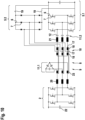
- Fig. 1 shows a circuit diagram of a multi-phase DC/DC-converter circuit 1 according to a first embodiment of the present invention. Henceforth, unless the number of phases is specified, the following will refer to the "multi-phase DC/DC-converter circuit 1" as "converter 1".
- the converter 1 comprises a transformer 8 with a primary side 9 and a secondary side 10, a primary side switching circuit 2, and a secondary side rectifier circuit 5.
- the converter 1 furthermore comprises a DC-link capacitor 22 and primary side resonant inductors 20.
- the converter 1 is an LLC converter (also referred to as "LLC topology").
- the converter 1 of the present embodiment is a six phase DC/DC-converter. Due to the shown six-phase LLC topology, current through the winding reduces by half as compared to three-phase LLC topologies. Voltage across windings of the transformer 8 also reduces. This leads to reduced losses per winding. Therefore, to achieve size reduction, frequency of operation can be increased. Thus, the six-phase topology results in a smaller transformer 8 by distributing losses across an increased number of windings. Smaller current and high frequency operation can be helpful to design planar transformer (as will be discussed later with respect to Figs. 12 to 14 ), which leads to advantageously automated fabrication processes.
- the primary side switching circuit 2 comprises six primary side switching legs 3. Each of the six primary side switching legs 3 comprises two switch elements 4. Therefore, the converter 1 of the present embodiment is a two-level converter 1.
- the primary side 9 of the transformer 8 comprises six windings 23.
- the secondary side rectifier circuit 5 comprises 6 secondary side rectifier legs 6. Each of the six secondary side rectifier legs 6 comprises two rectifier elements 7.
- the secondary side rectifier circuit 5 is a bridge configuration.
- the secondary side 10 of the transformer 8 comprises six windings 18.
- the actual primary side 9) of the transformer 8 will always be referred to as the primary side 9, even though in a bidirectional case, when current is transformed from right to left (in Fig. 1 , from secondary side 10 to primary side 9), their nomenclature would be switched depending on current flow. Furthermore, even though a bidirectional configuration also allows a unidirectional operation, a configuration in which bidirectional transformation is feasible will nonetheless be referred to as bidirectional. In another sense, "unidirectional" may also be understood as “non-bidirectional".
- the converter 1 of the present embodiment comprises a resonant capacitor network 11.
- the resonant capacitor network 11 comprises a plurality of capacitors 12. Each of the capacitors 12 is connected to the primary winding 23 of the transformer 8 as well as to the primary side resonant inductance 20.
- a capacitor 12 together with a resonant inductance 20 are commonly referred to as resonant network ("LC" of "LLC", further "L” being winding 23 of transformer 8), as they together form a resonance circuit.
- the capacitors 12 of the resonant capacitor network 11 of the present embodiment comprise a double star configuration 13 (also referred to as a "double star connection of capacitors"). Such a configuration reduces voltage stress on each capacitor 12.
- Fig. 2 shows a circuit diagram of a multi-phase DC/DC-converter circuit 1 according to a second embodiment of the present invention.
- the capacitors 12 of the resonant capacitor network 11 of the present embodiment comprise a hexagonal configuration 14 (also referred to as a "hexagonal connection of capacitors").
- a hexagonal configuration 14 also referred to as a "hexagonal connection of capacitors"
- Such a configuration is an alternative configuration of a delta configuration and achieves lower current stress on each capacitor 12.
- Fig. 3 shows a circuit diagram of a multi-phase DC/DC-converter circuit 1 according to a third embodiment of the present invention.
- the capacitors 12 of the resonant capacitor network 11 of the present embodiment comprise a double delta configuration 15 (also referred to as a "double delta connection of capacitors").
- a double delta configuration 15 also referred to as a "double delta connection of capacitors”
- Such a configuration similar to the hexagonal configuration 14 of Fig. 2 , achieves a lower current stress on each capacitor 12.
- Fig. 4 shows a circuit diagram of a multi-phase DC/DC-converter circuit 1 according to a fourth embodiment of the present invention.
- the converter 1 is configured to be bidirectional. Therefore, transformation is possible from the primary side 9 to the secondary side 10 and from the secondary side 10 to the primary side 9.
- the secondary side 10 of the transformer 8 herein also comprises resonant inductances 21 (secondary side resonant inductances 21).
- the converter 1 of the present embodiment preferably comprises two resonant capacitor networks 11, namely a first resonant capacitor network 11.1 and a second resonant capacitor network 11.2.
- both the first resonant capacitor network 11.1 and the second resonant capacitor network 11.2 are each a double star configuration 13.
- the first resonant capacitor network 11.1 is connected to the primary side 9 of the transformer 8.
- the second resonant capacitor network 11.2 is connected to the secondary side 10 of the transformer 8.
- the first resonant capacitor network 11.1 forms, together with the primary side resonant inductances 20, a primary side resonant network.
- the second resonant capacitor network 11.2 forms, together with the secondary side resonant inductances 21, a secondary side resonant network.
- both resonant capacitor networks 11.1 and 11.2 comprise the double star configuration 13
- both may alternatively comprise the hexagonal configuration 14 ( Fig. 2 ) or the delta configuration 15 ( Fig. 3 ).
- the resonant capacitor networks 11.1 and 11.2 may comprise a combination, i.e. two different, of the foregoing described configurations.
- resonant capacitor networks 11, 11.1, and 11.2 each have different circuit parameters such as resonance inductance and resonance capacitance. These different circuit parameters essentially lead to different gain curves (voltage gain versus operating frequency) of the converter 1. Depending on the gain needed for the application, for example depending on a voltage level of a battery to be charged by the converter 1, the converter 1 is operated at different frequencies.
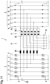
- Fig. 5 shows a circuit diagram of a multi-phase DC/DC-converter circuit 1 according to a fifth embodiment of the present invention.
- the multi-phase DC/DC-converter 1 is a three-phase converter 1, especially in a unidirectional configuration (the secondary side rectifier circuit 5 comprising diodes as rectifier elements 7). Therefore, the primary side switching circuit 2 comprises three primary side switching legs 3, each having two switch elements 4. Further, the converter 1 comprises three resonant inductances 20 on the primary side 9.
- the secondary side rectifier circuit 5 comprises three secondary side rectifier legs 6, each having two diodes 7.
- the transformer 8 comprises three primary windings 23 and three secondary windings 18.
- the converter 1 of the present embodiment comprises one resonant capacitor network 11 connected to the primary side 9 of the transformer 8.
- the resonant capacitor network 11 of the present embodiment comprises two configurations of capacitors 12 and switching units 16 (in the present embodiment, three switching units 16), which switch between configurations or connection schemes of the capacitors 12.
- the resonant capacitor network 11 comprises a star configuration and a delta configuration.
- the resonant capacitor network 11 In the switch-state shown in Fig. 5 , the resonant capacitor network 11 is in the star configuration (compare with Fig. 1 ). If all switching units 16 are switched, the resonant capacitor network 11 will be in the delta configuration (compare with Fig. 3 ). Thereby, the resonant capacitor network 11 can be switched between star configuration and delta configuration.
- the switching of switches 16 may be carried out by a control unit (not shown).
- the control unit may simultaneously control the switching units 16 as well as the primary side switching circuit 2 and/or the secondary side rectifier circuit 5 (for example in the bidirectional case).
- Fig. 6 shows a graph indicating gain curves for the converter 1 shown in Fig. 5 .
- the abscissa 24 of the graph indicates operating frequency of the converter 1
- the ordinate 25 of the graph indicates voltage gain.
- Shown curve 26 is a gain curve 26 of the delta connection (switching units 16 in Fig. 5 being switched to state not shown)
- shown curve 27 is a gain curve 27 of the star connection (switching units 16 in state as shown in Fig. 5 ).
- resonant frequency is indicated by "f".
- each connection scheme has a different gain at different frequencies. If a different gain is required to be supplied from the converter 1, and the required gain is not suppliable (at respectively switched connection scheme) near resonance f, then the switching units 16 may be switched to the different connection scheme so as to supply the required gain closer to resonance f of the converter 1. For example, if a gain of roughly 0.5 is required, the gain curve 26, i.e. delta connection scheme, may be chosen, since it can supply the gain of 0.5 closer to resonance f than the gain curve 27. Alternatively, if a gain of roughly 1 is required, the gain curve 27 may be chosen.
- the resonant capacitor network 11 as demonstrated above comprises two configurations, herein the star configuration and the delta configuration.
- a switchable resonant capacitor network 11 is not limited thereto.
- such a resonant capacitor network 11 can comprise a combination of any of the foregoing described configurations.
- such a resonant capacitor network 11 can comprise two out of: star, double star, delta, double delta, and hexagonal.
- the two configurations are preferably different configurations (as is the case with star and delta configurations).
- the resonant capacitor network 11 may also comprise two of the same configurations, for example two delta or double delta configurations, wherein the capacities of the capacitors 12 and/or the inductance values of the resonant inductances 20 (or respectively on the secondary side: inductances 21) are different, and at least one switching unit 16 switches therebetween.
- Fig. 7 shows a circuit diagram of a multi-phase DC/DC-converter circuit 1 according to a sixth embodiment of the present invention.
- the converter 1 is three-phase and bidirectional (switches 7 in secondary side rectifier circuit 5).
- the converter 1 comprises two resonant capacitor networks 11, namely a first resonant capacitor network 11.1 connected to the primary side 9 and a second resonant capacitor network 11.2 connected to the secondary side 10.
- both the first resonant capacitor network 11.1 and the second resonant capacitor network 11.2 each comprise the star configuration and the delta configuration of capacitors 12, with switching units 16 allowing switching therebetween.
- the resonant capacitor networks 11.1 and 11.2 do not need to be the same, and can each have a configuration as discussed above. Furthermore, their switch-states also do not need to be the same. Instead, they can be switched independently from one another.
- Fig. 8 shows a circuit diagram of a multi-phase DC/DC-converter circuit 1 according to a seventh embodiment of the present invention.
- the converter 1 of the present embodiment is a six phase converter 1 with a bidirectional configuration. Furthermore, the converter 1 comprises the two resonant capacitor networks 11.1 and 11.2. Each of the two resonant capacitor networks 11.1 and 11.2 is switchable between the delta configuration (double delta configuration) and the star configuration.
- the resonant capacitor networks 11.1 and 11.2 do not need to be the same, although this is preferable, and also do not need to be switched identical to one another.
- Fig. 9 shows a circuit diagram of a multi-phase DC/DC-converter circuit 1 according to an eighth embodiment of the present invention.
- the converter 1 of the present embodiment is a three phase converter 1.
- the circuit diagram shown in Fig. 9 is re-arranged as compared to Figs. 1 to 8 (especially for example Fig. 5 ) with respect to the primary side 9 and the secondary side 10 of the transformer 8 for higher clarity regarding the differing features of the present embodiment.
- the transformer 8 is shown in a side-to-side layout as compared to a up-down layout shown in figs. 1 to 8 .
- the converter 1 comprises a first resonant capacitor network 11.1 in a delta configuration.
- the converter 1 of the present embodiment comprises two secondary side rectifier circuits 5, namely a first secondary side rectifier circuit 5.1 and a second secondary side rectifier circuit 5.2.
- the first secondary side rectifier circuit 5.1 comprises switches as rectifier elements 7. Thereby, the first secondary side rectifier circuit 5.1 allows bidirectional operation of the converter 1.
- the second secondary side rectifier circuit 5.2 comprises diodes as rectifier elements 7.
- the second secondary side rectifier circuit 5.2 allows unidirectional operation of the converter 1 (i.e. non-bidirectional operation of the converter 1).
- the converter 1 comprises rectifier circuit switching units 19 connected to outputs of the first and second secondary side rectifier circuits 5.1, 5.2.
- the rectifier circuit switching units 19 thereby allow switching between the (use of) first secondary side rectifier circuit 5.1 and the second secondary side rectifier circuit 5.2.
- DC-DC converters are their use in charging batteries of electric vehicles.
- the chargers or corresponding circuits in the vehicle
- the chargers comprise such DC-DC converters in unidirectional configuration, with resonances and circuit parameters set to be close to ideal for charging batteries.
- the charging circuits comprised in the vehicles have recently been switched to bidirectional configurations.
- bidirectional configurations can commonly only be set (with regard to resonances and circuit parameters) so as to be non-ideal for both charging and discharging applications (and therefore only somewhat ideal for both applications simultaneously).
- the converter 1 comprises two secondary side rectifier circuits 5.1, 5.2, one for a bidirectional use (i.e. the first rectifier circuit 5.1) and one for unidirectional use (i.e. the second rectifier circuit 5.2).
- the second resonant capacitor network 11.2 connected to the secondary side 10 of the transformer is connected between both of the two secondary side rectifier circuits 5.1, 5.2. Therefore, in the present embodiment, the converter 1 comprises, on the secondary side 10 of the transformer 8, a single resonant capacitor network 11.2 connected between the secondary side 10 of the transformer 8 and the plurality of, here two, secondary side rectifier circuits 5.1, 5.2.
- the transformer 8 comprises two secondary windings 18.
- Each of the secondary side rectifier circuits 5.1, 5.2 is connected to a different tapping 17 of the secondary windings 18. Thereby, an effective turn-ratio is different for each of the secondary side rectifier circuits 5.1, 5.2. Therefore, the configuration of the present embodiment achieves higher efficiency when operating in forward mode (i.e. from primary side 9 to secondary side 10) via the second secondary side rectifier circuit 5.1 than when doing so via the first secondary side rectifier circuit 5.2.
- Fig. 10 shows a circuit diagram of a multi-phase DC/DC-converter circuit 1 according to a ninth embodiment of the present invention.
- the converter 1 of the present embodiment also comprises two secondary side rectifier circuits 5.1, 5.2 with the rectifier circuit switching units 19 therebetween, and is a three phase converter.
- Fig. 10 shows an example in which the resonant capacitor network 11.2 of the secondary side 10 is connected to only one of the plurality of secondary side rectifier circuits 5.1 or 5.2.
- the resonant capacitor network 11.2 of the secondary side 10 is connected only to the first secondary side rectifier circuit 5.1, i.e. the bidirectional rectifier circuit.
- resonant capacitor network (not shown) on the secondary side 10 connected only to the second secondary side rectifier circuit 5.2.
- the converter 1 in an operation mode (charging, forward mode) employing the second secondary side rectifier circuit 5.2 is unaffected by the resonant network 11.2 (in addition to the secondary side resonance inductances 21 connected thereto) for the first secondary side rectifier circuit 5.1.
- each of the operations forward or backward mode
- Fig. 11 shows a circuit diagram of a multi-phase DC/DC-converter circuit 1 according to a tenth embodiment of the present invention.
- the converter 1 of the present embodiment is similar to the converter 1 of the first embodiment in that the capacitors 12 of the resonant capacitor network 11 of the present embodiment also comprise a double star configuration 13.
- the secondary side 10 of the transformer 8 is connected in a delta configuration.
- Such a delta configuration of the secondary side 10 of the transformer 8 may preferably be combined with or employed in any one of the foregoing described embodiments.
- Fig. 12 shows a schematic top view of a transformer 8 included in a multi-phase DC/DC-converter circuit 1 according to an eleventh embodiment of the present invention.
- Fig. 13 shows a schematic side view of the transformer 8 of the multi-phase DC/DC-converter circuit 1 according to the eleventh embodiment of the present invention.
- Fig. 14 shows a schematic cross-sectional top view of the transformer 8 of the multi-phase DC/DC-converter circuit 1 according to the tenth embodiment of the present invention.
- Figs. 12 to 14 show a detail view of a configuration of the transformer 8 included in the converter 1, especially in any one of the converters 1 of the foregoing embodiments.
- the converter 1 comprises a planar transformer 8 with integrated primary side resonant inductances 20 and integrated secondary side resonant inductances 21.
- the converter 1 of Figs. 12 and 13 is a six phase converter 1 according to any one of the foregoing described embodiments. Therefore, the transformer 8 of Figs. 12 and 13 is a six phase planar transformer 8.
- a top view of a top magnetic core 28 is shown. Hashed lines indicate components underneath the top magnetic core 28, and are shown in further detail in Figs. 13 and 14 .
- the planar transformer 8 of the present embodiment comprises the top magnetic core 28 and a bottom magnetic core 29.
- Each of the top and bottom magnetic cores 28, 29 comprises magnetic core legs 30 and 31.
- the magnetic core legs 31 in the middle of Fig. 12 i.e. in the top view middle of the transformer 8) correspond to magnetic core legs 31 for the transformer windings 18, 23 (i.e. primary/secondary windings 23, 18).
- magnetic core legs 30 can be seen, which correspond to the outer legs 30 on either side of the transformer winding magnetic core legs 31 in Fig. 12 .
- These outer legs 30 correspond to magnetic core legs 30 for inductor windings 20 and 21 (compare Figs. 1 to 11 ).
- the top row of outer magnetic core legs 30 carries the resonant inductances (winding and core leg) 20 of the primary side 9, whereas the bottom row of outer magnetic core legs 30 carries the resonant inductances 21 of the secondary side 10 of the transformer 8.
- the windings 18, 20, 21, and 23, corresponding to the resonant inductances 21 and the transformer 8 windings, are printed on a printed circuit board 35 (PCB).
- the PCB 35 comprises openings into which the respective core legs 30, 31 are inserted.
- air gaps 32 are provided between opposing legs (compare Fig. 13 ).
- the transformer 8 of the converter 1 is formed as a planar transformer 8 with integrated primary side resonant inductors 20 and integrated secondary side resonant inductors 21.
- the further components for example the primary side switching circuit 2 and/or the at least one secondary side rectifier circuit 5 and/or the at least one resonant capacitor network 11 can appropriately also be printed on the PCB 35.
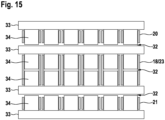
- Fig. 15 shows a schematic side view of a transformer 8 included in a multi-phase DC/DC-converter circuit 1 according to a twelfth eleventh embodiment of the present invention.
- the converter 1 of the present embodiment is a six-phase converter 1, wherein the transformer 8 is formed in a stacked configuration of cores 33 with legs 34.
- the cores 33 are in an EE ⁇ type configuration (the legs of the "E" correspond to magnetic core legs 34, the base of the "E” corresponding to the cores 33).
- the cores 33 are plate-shaped with the legs 34 projecting therefrom.
- the transformer windings 18, 23 as well as the primary side resonant inductor 20 windings and the secondary side resonant inductor 21 windings are shown. Air gaps 32 are provided therein between opposing legs 34 and between legs 34 and an adjacent core 33.
- embodiments may suitably be combined with one another. Where features of the converter 1 were shown with respect to a three-phase converter 1 example, such features can suitably also be implemented in the six-phase converter 1 examples. In particular, embodiments one to ten may be combined with one another and/or with any one of embodiments eleven (planar configuration) and/or twelve (stacked configuration).
- circuit diagrams may be understood as describing exact connection schemes, such that two elements directly connected to one another therein, especially electrically, are to be understood as such, especially with no other (active) elements connected therebetween.
Landscapes
- Engineering & Computer Science (AREA)
- Power Engineering (AREA)
- Dc-Dc Converters (AREA)
Priority Applications (3)
| Application Number | Priority Date | Filing Date | Title |
|---|---|---|---|
| EP23157968.1A EP4422051A1 (de) | 2023-02-22 | 2023-02-22 | Mehrphasige gleichstromwandlerschaltung |
| CN202410106770.8A CN118539757A (zh) | 2023-02-22 | 2024-01-25 | 多相直流/直流转换器 |
| US18/424,895 US20240283368A1 (en) | 2023-02-22 | 2024-01-29 | Multi-phase dc/dc converter |
Applications Claiming Priority (1)
| Application Number | Priority Date | Filing Date | Title |
|---|---|---|---|
| EP23157968.1A EP4422051A1 (de) | 2023-02-22 | 2023-02-22 | Mehrphasige gleichstromwandlerschaltung |
Publications (1)
| Publication Number | Publication Date |
|---|---|
| EP4422051A1 true EP4422051A1 (de) | 2024-08-28 |
Family
ID=85328725
Family Applications (1)
| Application Number | Title | Priority Date | Filing Date |
|---|---|---|---|
| EP23157968.1A Pending EP4422051A1 (de) | 2023-02-22 | 2023-02-22 | Mehrphasige gleichstromwandlerschaltung |
Country Status (3)
| Country | Link |
|---|---|
| US (1) | US20240283368A1 (de) |
| EP (1) | EP4422051A1 (de) |
| CN (1) | CN118539757A (de) |
Families Citing this family (1)
| Publication number | Priority date | Publication date | Assignee | Title |
|---|---|---|---|---|
| CN120566912A (zh) * | 2025-05-08 | 2025-08-29 | 福建臻格科技有限公司 | 一种宽电压范围的双向dcdc电路及控制方法 |
Citations (7)
| Publication number | Priority date | Publication date | Assignee | Title |
|---|---|---|---|---|
| WO2011074977A2 (en) | 2009-12-17 | 2011-06-23 | Eltek Valere As | Resonant circuit and resonant dc/dc converter |
| EP2887523A1 (de) * | 2013-12-20 | 2015-06-24 | Huawei Technologies Co., Ltd. | Resonanter bidirektionaler Umrichter, unterbrechungsfreie Stromversorgungsvorrichtung und Steuerungsverfahren |
| EP3675340A1 (de) * | 2018-12-19 | 2020-07-01 | Delta Electronics, Inc. | Llc-resonanzwandlersystem |
| US10873265B2 (en) * | 2018-06-12 | 2020-12-22 | Virginia Tech Intellectual Properties, Inc. | Bidirectional three-phase direct current (DC)/DC converters |
| JP2021153382A (ja) | 2020-03-18 | 2021-09-30 | 株式会社Gsユアサ インフラシステムズ | 3相llcコンバータ |
| US11233462B2 (en) | 2019-11-08 | 2022-01-25 | Delta Electronics (Shanghai) Co., Ltd. | Power converter and power supply system |
| US11404967B2 (en) | 2018-06-12 | 2022-08-02 | Virginia Tech Intellectual Properties, Inc. | Interleaved converters with integrated magnetics |
Family Cites Families (3)
| Publication number | Priority date | Publication date | Assignee | Title |
|---|---|---|---|---|
| EP4246787A1 (de) * | 2022-03-14 | 2023-09-20 | Delta Electronics (Thailand) Public Co., Ltd. | Dc/dc wandler mit mehrstufiger technologie |
| US20250132686A1 (en) * | 2023-10-20 | 2025-04-24 | Infineon Technologies Austria Ag | Multi-Phase Resonant Power Converter |
| EP4618396A1 (de) * | 2024-03-11 | 2025-09-17 | Delta Electronics (Thailand) Public Co., Ltd. | Steuerungsverfahren zum betrieb eines mehrphasenwandlers, mehrphasen-serienresonanzwandler, mehrphasen-llc-resonanzwandler |
-
2023
- 2023-02-22 EP EP23157968.1A patent/EP4422051A1/de active Pending
-
2024
- 2024-01-25 CN CN202410106770.8A patent/CN118539757A/zh active Pending
- 2024-01-29 US US18/424,895 patent/US20240283368A1/en active Pending
Patent Citations (7)
| Publication number | Priority date | Publication date | Assignee | Title |
|---|---|---|---|---|
| WO2011074977A2 (en) | 2009-12-17 | 2011-06-23 | Eltek Valere As | Resonant circuit and resonant dc/dc converter |
| EP2887523A1 (de) * | 2013-12-20 | 2015-06-24 | Huawei Technologies Co., Ltd. | Resonanter bidirektionaler Umrichter, unterbrechungsfreie Stromversorgungsvorrichtung und Steuerungsverfahren |
| US10873265B2 (en) * | 2018-06-12 | 2020-12-22 | Virginia Tech Intellectual Properties, Inc. | Bidirectional three-phase direct current (DC)/DC converters |
| US11404967B2 (en) | 2018-06-12 | 2022-08-02 | Virginia Tech Intellectual Properties, Inc. | Interleaved converters with integrated magnetics |
| EP3675340A1 (de) * | 2018-12-19 | 2020-07-01 | Delta Electronics, Inc. | Llc-resonanzwandlersystem |
| US11233462B2 (en) | 2019-11-08 | 2022-01-25 | Delta Electronics (Shanghai) Co., Ltd. | Power converter and power supply system |
| JP2021153382A (ja) | 2020-03-18 | 2021-09-30 | 株式会社Gsユアサ インフラシステムズ | 3相llcコンバータ |
Non-Patent Citations (1)
| Title |
|---|
| KHAN AKIF ZIA ET AL: "A Three-Phase Dual-Active-Bridge DC-DC Converter With Reconfigurable Resonant Network for Efficient Wide Voltage Range Operation", IEEE TRANSACTIONS ON POWER ELECTRONICS, INSTITUTE OF ELECTRICAL AND ELECTRONICS ENGINEERS, USA, vol. 35, no. 2, 1 February 2020 (2020-02-01), pages 1322 - 1339, XP011758005, ISSN: 0885-8993, [retrieved on 20191115], DOI: 10.1109/TPEL.2019.2920115 * |
Also Published As
| Publication number | Publication date |
|---|---|
| CN118539757A (zh) | 2024-08-23 |
| US20240283368A1 (en) | 2024-08-22 |
Similar Documents
| Publication | Publication Date | Title |
|---|---|---|
| US12027986B2 (en) | Magnetic integration of three-phase resonant converter and accessory power supply | |
| US7746669B2 (en) | Bidirectional battery power inverter | |
| AU2019447744B2 (en) | Integrated charger and motor control system comprising a transformer and multi-level power converters | |
| Lee et al. | New combined OBC and LDC system for electric vehicles with 800 V battery | |
| Bhattacharya et al. | Multiphase bidirectional flyback converter topology for hybrid electric vehicles | |
| Fan et al. | High-frequency transformer isolated bidirectional DC–DC converter modules with high efficiency over wide load range for 20 kVA solid-state transformer | |
| JP5855133B2 (ja) | 充電装置 | |
| Park et al. | Nonisolated ZVZCS resonant PWM DC–DC converter for high step-up and high-power applications | |
| US20240186908A1 (en) | Power supply apparatus, three-phase transformer circuit, and charging pile | |
| Balestero et al. | A dc–dc converter based on the three-state switching cell for high current and voltage step-down applications | |
| EP3700074B1 (de) | Gleichspannungswandler | |
| Mira et al. | Review of high efficiency bidirectional dc-dc topologies with high voltage gain | |
| EP4354473A1 (de) | Transformator eines elektrischen systems zur gleichspannungswandlung und zum laden von batterien eines fahrzeugs | |
| EP4354695A1 (de) | Elektrisches system zur gleichspannungswandlung und zum laden von batterien eines fahrzeugs | |
| US20240283368A1 (en) | Multi-phase dc/dc converter | |
| Pourjafar et al. | Review and outlook of isolated capacitive coupling based converters | |
| US20240047120A1 (en) | Balanced boost dc/dc converter | |
| US12463427B2 (en) | Method and circuit for an integrated DC converter in an AC battery | |
| Chen et al. | Design and implementation of two-stage boost and full-bridge resonant converter for wide-range APMs | |
| Bornwasser | Series-resonant-converter with galvanic isolation and> 99% efficiency | |
| Kanakri et al. | Capacitorless notch resonant converters for miniaturized llclc resonant converters in electric vehicle charging applications | |
| Solanki et al. | 22 kW High Efficiency Wide Voltage Range 3-Phase LLC Converter for On-Board-Charger Applications | |
| US12567805B2 (en) | Voltage converter with wide range output | |
| Costa et al. | Improved Design for a High Current DC/DC Converter in Fuel Cell Vehicle Systems | |
| EP4329142A1 (de) | Isolierter bidirektionaler ac/dc-dc-stromwandler |
Legal Events
| Date | Code | Title | Description |
|---|---|---|---|
| PUAI | Public reference made under article 153(3) epc to a published international application that has entered the european phase |
Free format text: ORIGINAL CODE: 0009012 |
|
| STAA | Information on the status of an ep patent application or granted ep patent |
Free format text: STATUS: THE APPLICATION HAS BEEN PUBLISHED |
|
| AK | Designated contracting states |
Kind code of ref document: A1 Designated state(s): AL AT BE BG CH CY CZ DE DK EE ES FI FR GB GR HR HU IE IS IT LI LT LU LV MC ME MK MT NL NO PL PT RO RS SE SI SK SM TR |
|
| STAA | Information on the status of an ep patent application or granted ep patent |
Free format text: STATUS: REQUEST FOR EXAMINATION WAS MADE |
|
| 17P | Request for examination filed |
Effective date: 20250227 |