EP4247221B1 - Dispositif de support d'étagère rotatif permettant de supporter des étagères amovibles de meuble - Google Patents
Dispositif de support d'étagère rotatif permettant de supporter des étagères amovibles de meuble Download PDFInfo
- Publication number
- EP4247221B1 EP4247221B1 EP21824016.6A EP21824016A EP4247221B1 EP 4247221 B1 EP4247221 B1 EP 4247221B1 EP 21824016 A EP21824016 A EP 21824016A EP 4247221 B1 EP4247221 B1 EP 4247221B1
- Authority
- EP
- European Patent Office
- Prior art keywords
- shelf
- pin
- seat
- main body
- furniture
- Prior art date
- Legal status (The legal status is an assumption and is not a legal conclusion. Google has not performed a legal analysis and makes no representation as to the accuracy of the status listed.)
- Active
Links
Images
Classifications
-
- A—HUMAN NECESSITIES
- A47—FURNITURE; DOMESTIC ARTICLES OR APPLIANCES; COFFEE MILLS; SPICE MILLS; SUCTION CLEANERS IN GENERAL
- A47B—TABLES; DESKS; OFFICE FURNITURE; CABINETS; DRAWERS; GENERAL DETAILS OF FURNITURE
- A47B57/00—Cabinets, racks or shelf units, characterised by features for adjusting shelves or partitions
- A47B57/06—Cabinets, racks or shelf units, characterised by features for adjusting shelves or partitions with means for adjusting the height of the shelves
- A47B57/20—Cabinets, racks or shelf units, characterised by features for adjusting shelves or partitions with means for adjusting the height of the shelves consisting of tongues, pins or similar projecting means coacting with openings
-
- F—MECHANICAL ENGINEERING; LIGHTING; HEATING; WEAPONS; BLASTING
- F16—ENGINEERING ELEMENTS AND UNITS; GENERAL MEASURES FOR PRODUCING AND MAINTAINING EFFECTIVE FUNCTIONING OF MACHINES OR INSTALLATIONS; THERMAL INSULATION IN GENERAL
- F16B—DEVICES FOR FASTENING OR SECURING CONSTRUCTIONAL ELEMENTS OR MACHINE PARTS TOGETHER, e.g. NAILS, BOLTS, CIRCLIPS, CLAMPS, CLIPS OR WEDGES; JOINTS OR JOINTING
- F16B12/00—Jointing of furniture or the like, e.g. hidden from exterior
- F16B12/10—Jointing of furniture or the like, e.g. hidden from exterior using pegs, bolts, tenons, clamps, clips, or the like
- F16B12/12—Jointing of furniture or the like, e.g. hidden from exterior using pegs, bolts, tenons, clamps, clips, or the like for non-metal furniture parts, e.g. made of wood, of plastics
- F16B12/24—Jointing of furniture or the like, e.g. hidden from exterior using pegs, bolts, tenons, clamps, clips, or the like for non-metal furniture parts, e.g. made of wood, of plastics using separate pins, dowels, or the like
-
- F—MECHANICAL ENGINEERING; LIGHTING; HEATING; WEAPONS; BLASTING
- F16—ENGINEERING ELEMENTS AND UNITS; GENERAL MEASURES FOR PRODUCING AND MAINTAINING EFFECTIVE FUNCTIONING OF MACHINES OR INSTALLATIONS; THERMAL INSULATION IN GENERAL
- F16B—DEVICES FOR FASTENING OR SECURING CONSTRUCTIONAL ELEMENTS OR MACHINE PARTS TOGETHER, e.g. NAILS, BOLTS, CIRCLIPS, CLAMPS, CLIPS OR WEDGES; JOINTS OR JOINTING
- F16B12/00—Jointing of furniture or the like, e.g. hidden from exterior
- F16B12/10—Jointing of furniture or the like, e.g. hidden from exterior using pegs, bolts, tenons, clamps, clips, or the like
- F16B12/12—Jointing of furniture or the like, e.g. hidden from exterior using pegs, bolts, tenons, clamps, clips, or the like for non-metal furniture parts, e.g. made of wood, of plastics
- F16B12/26—Jointing of furniture or the like, e.g. hidden from exterior using pegs, bolts, tenons, clamps, clips, or the like for non-metal furniture parts, e.g. made of wood, of plastics using snap-action elements
Definitions
- the present invention relates to a shelf-supporting device for supporting furniture shelves for the reversible and easily removable connection of a shelf to the opposite shoulders of a piece of furniture.
- the device according to the present invention responds to the need, felt in the sector, for being able to provide furniture shelves with supporting devices that create a simple and effective connection with the shoulders of a piece of furniture, that are miniaturized so as to reduce the aesthetic impact to the minimum and possibly disappearing completely from sight when the shelf is assembled, but at the same time offering a safe connection of the shelf to the shoulders of the furniture, preventing undesired accidental disengagements.
- shelf brackets in the field, and exert the function of stably but removably supporting and fixing a horizontal element (shelf) of a piece of furniture between two vertical elements commonly called shoulders. Said shelves and said shoulders are arranged perpendicular to each other.
- Said shelves and said shoulders are arranged perpendicular to each other.
- Shelf brackets of this type configured for being inserted into a housing seat formed within the thickness of a shelf from which only the pin generally protrudes, are known from the state of the art.
- the document DE 10027015 describes a concealed floor mounting for shelving with an outer case fixed on a bore in the floor.
- the case contains a sprung rod which engages in one of a row of holes formed in the base of the shelving.
- the sprung rod has a support tip, slide section, spring and mounting cap.
- the support tip can have a rounded lower surface to fit the corresponding hole in the shelving.
- the document IT 201900005830 describes a device for supporting a removable panel with respect to a wall of an article of furniture.
- the device comprises a hollow body, a movable element slidably arranged inside the hollow body at least between a first operating position, wherein a terminal portion of the movable element is projecting from the hollow body, and a second operating position, and a main elastic element interposed between the bottom and the movable element and configured to move the latter towards the first operating position.
- the device further comprises at least one return elastic element active on the movable element to return it from the first operating position to the second operating position.
- the return elastic element is configurable between an inactive condition and an active condition to return the movable element to the second operating position following a triggering movement.
- Some of these known shelf-supporting devices comprise means for moving the pin which are kept in the operating position by opposing means, such as for example a spring, and can be actuated manually by the user in the retraction movement of the pin which allows the pin to be released from the housing seat of the pin provided in the shoulder of the furniture.
- opposing means such as for example a spring
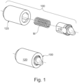
- shelf bracket is the device illustrated in Italian patent application nr. IT201900020124 , in the name of the same Applicant, which relates to a shelf-supporting device of which a possible preferred embodiment is shown in Figure 1 .
- This known type shelf-supporting device 100 allows the reversible connection of a shelf to the opposite shoulders of a piece of furniture and comprises a main body 120 which houses a pin 110 in its interior, movable along a longitudinal axis X.
- the pin 110 can be translated along said axis X against the action of opposing means composed, in the example, of the helical spring M, between a retracted non-operating position in which the pin does not protrude from the main body 120 or protrudes for a short distance, and an operating position in which the free end or tip P of the pin 110 protrudes from said shelf for a distance sufficiently long for it to be inserted into the housing seat of said pin formed on one of said shoulders and provide a stable coupling, even if reversible between the shelf and the shoulders.
- the device of the known type provides that the tip P of the pin 110 ends with a tilted surface or tilted plane Pa suitable for cooperating with the entry edge of said seat so that, when said shelf is pushed upwards, the pin 110 becomes disengaged from said seat, overcoming the action of the opposing means, in the example consisting of the spring M, allowing the shelf to be removed from the piece of furniture.
- shelf-supporting devices of the type described above can be easily released by pushing upwards, and this can lead to the accidental release of the shelf, for example during the transportation of the furniture itself.
- the furniture is in fact generally transported with the shelves assembled to the shoulders, but, during the transportation phase of the furniture, it is easily and frequently overturned with respect to its position of normal use.
- the weight of the shelves equipped with the shelf brackets of the known type described so far is sufficient for ensuring that the pins of the shelf brackets become disengaged from their respective seats provided in the shoulders of the furniture, exactly as what happens when the operator deliberately pushes the shelf upwards to remove it from the shoulders of the furniture.
- a further drawback affecting the shelf-supporting devices of the known type, including that described above, relates to the fact that they are generally designed for being assembled inside the shelf in a predetermined way, forcing the operator to assemble the shelf to the shoulders of the piece of furniture according to a predetermined, non-modifiable movement.
- the shelf-supporting device of the type known from Italian patent application nr. IT201900020124 in the name of the same Applicant requires that the shelf be assembled on the furniture by inserting it from above with a vertical movement, the same vertical movement, this time upwards, which allows the release of the shelf brackets and the disengagement of the shelf from the shoulders.
- the undertaking of the present invention is to solve the drawbacks affecting shelf-supporting devices of the type known from the state of the art.
- the undertaking of the present invention is to provide a shelf-supporting device capable of completely eliminating the risk of accidental disengagement of the shelf from the shoulders of the furniture.
- the objective of the present invention is to provide a shelf-supporting device which avoids the accidental release of the shelf from the shoulders of the furniture due to the weight of the shelf itself, for example when the furniture is overturned, as often occurs in the transportation phase of the furniture itself.
- a further objective of the present invention is to provide a shelf bracket that is more versatile, as it can be assembled in the shelf so as to allow the operator to decide whether to proceed with the assembly from the top or the front of the shelf to the shoulders of the furniture.
- Yet another objective of the present invention is to provide a shelf bracket that is both versatile and easy to use, capable of minimizing, if not completely eliminating, the aesthetic impact, proving to be invisible both when used with shelves destined for being seen from above by the user, and also when used with shelves destined for being seen from below, allowing any trace of the presence of the device and in particular the presence of manoeuvring holes, to be completely eliminated from sight, and which can be easily associated with the shoulders of a piece of furniture and easily removable from the same, in order to allow a simple, fast and immediate assembly and/or disassembly of the shelf without the use of any manoeuvring tool.
- a shelf-supporting device for the reversible connection of a shelf to the shoulders of a piece of furniture according to the enclosed claim 1; the invention also relates to the combination of this type of shelf bracket and a tool for its assembly, according to the respective enclosed claim.
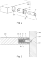
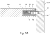
- a shelf-supporting device 30 is described for the reversible connection of a shelf 200 to the opposite shoulders 300 of a piece of furniture, according to a preferred embodiment of the present invention.
- the shelf-supporting device 30 is of the type suitable for creating the connection by means of a pin 11 associated with the shelf 200 and configured for protruding from the transverse edge 201 of said shelf 200 and suitable for being inserted into a corresponding housing hole or seat 301 formed on the shoulder 300 of a piece of furniture.
- the shelf-supporting device 30 is of the type suitable for being inserted into a seat 201 formed within the thickness of said shelf 200 and for this purpose comprises a main body 12 with which a substantially longitudinal pin 11 is slidingly associated, preferably but not exclusively substantially cylindrical, movable along a longitudinal axial direction X against the action of opposing means M between an advanced operating position in which said pin 11 protrudes from said main body 12 and, when the device is assembled in a shelf, from said shelf 200 so as to be able to be inserted into a housing seat 301 formed on one of said shoulders 300, and a retracted non-operating position in which said pin 11 does not protrude from said main body 12, and consequently does not protrude from said shelf 200 when the device is associated with a shelf or protrudes so as to be able to be in any case released from said housing seat 301 of said shoulder 300.
- the pin 11 advantageously ends with a free end or tip P comprising a tilted surface Pa suitable for cooperating with the entry edge of said seat 301, as will be described in more detail hereunder.
- the shelf-supporting device 30 is characterized in that it further comprises a bush 20 which can be fixedly inserted into said seat 201 formed within the thickness of said shelf 200, so that the main body 12 is in turn inserted into the axial cavity 22 of said bush 20 rotatably with respect to the same between a first operating position A which allows the engagement and release of the shelf 200 to the shoulders 300 of the furniture, and a second blocking position B suitable for avoiding the accidental release of the shelf from the shoulders.
- the shelf-supporting device 30 is advantageously configured so that when the main body 12 is coupled with the bush 20 in said first operating position A, the tilted surface Pa of said pin 11 faces upwards, wherein the expression "upwards” means facing the upper surface of the shelf, i.e. the surface destined for facing upwards when the shelf is assembled to the furniture, and the furniture is correctly positioned on the ground.
- the tilted surface Pa cooperates with the upper edge 301' for the entry of the seat 301 when the shelf bracket 30 is positioned in correspondence with the housing seat 301, to allow the release of the shelf 200 from the shoulders 300 simply due to an upward thrust.
- the tilted surface Pa of the pin 11 when the main body 12 of the device 30 is rotated into said second blocking position B, the tilted surface Pa of the pin 11 is no longer facing upwards, it can be rotated by 10°, or 20°, or by 45°, preferably about 90° with respect to the vertical direction corresponding to the operating position A, and is therefore unable to cooperate with the upper entry edge 301' of the seat 301 when said shelf 200 is pushed upwards ( figure 3A ).
- the tilted surface Pa of said pin 11 is preferably tilted by approximately 90° with respect to the first operating position A, so as to be able to cooperate with the side entry edge 301" of said seat 301 and allow the release of the shelf 200 from the shoulder 300 when said shelf 200 is moved horizontally.
- Horizontal direction refers to a direction substantially perpendicular to the axial advancement direction X of the pin, and relates to the position of the shelf with respect to the shoulders, which is horizontal when the piece of furniture is correctly positioned on the ground.
- the pin 11 withdraws due to the interaction between the tilted surface Pa and the side edge 301" of the seat 301 when the shelf is moved horizontally.
- Said bush 20 and said main body 12 advantageously comprise positioning means for said main body 12 suitable for allowing the stable but reversible positioning of said main body 12 in said first operating position A.
- Said positioning means 23, 13 are suitable for preventing the rotation of said main body 12 with respect to said bush 20 when the main body is in said first operating position A.
- said positioning means comprise an engagement tooth 13 positioned on the outer surface of said main body 12, and a corresponding engagement seat 23 formed on the internal surface of said axial cavity 22 of said bush, said engagement tooth 13 being configured for being inserted into said engagement seat 23.
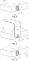
- the main body 12 of the device can be rotated with respect to the bush 20, which, on the other hand, is inserted fixed inside the seat 201 formed within the thickness of the shelf 200, preferably by means of a tool 40 configured for gripping said tip P of said pin 11, due to the fact that the main body 12 and the bush 20 of the device are generally assembled in the seat 201 flush with the edge of the shelf 202, without protruding from the same.
- Said tool 40 can advantageously comprise at least a portion configured as a thin foil 41 in which a seat 42 for housing said tip P of the pin 11 is formed, the thin foil 41 having a thickness suitable for allowing its insertion between the edge 202 of said shelf 200 from which the pin 11 of the shelf-supporting device 30 protrudes, and the shoulder 300 of the piece of furniture so as to be able to rotate said main body 12 with respect to said bush 20 even after said pin 11 has been inserted into said housing seat 301 formed in the shoulder 300 due to the thrust exerted by the opposing means M.
- the present invention therefore also relates to a method for connecting a shelf 200 to the shoulders 300 of a piece of furniture, wherein said shelf 200 is equipped with a plurality of shelf-supporting devices 30 according to what has been described so far.
- the method according to the invention provides for positioning said plurality of shelf-supporting devices 30 arranged according to said first operating position A wherein said tilted surface Pa of said pin 11 faces upwards, i.e. towards the upper surface of the shelf.
- each of said pins 11 of said shelf-supporting devices 30 By moving said shelf 200 with respect to said shoulder 300 so as to position each of said pins 11 of said shelf-supporting devices 30 in correspondence with the corresponding housing seat 301 formed in the shoulder 300 of the piece of furniture, so that said opposing means M push the pin 11 into the seat 301.
- the pin 11 When the pin 11 is inserted in the corresponding housing seat 301 formed in the shoulder 300, by rotating the main body 12 of at least one of said plurality of devices 30 with respect to its bush 20, the respective pin 11 is brought into said second blocking position B.
- the blocking position B can indifferently correspond to the pin rotated towards the front of the furniture, and in this case the shelf can be removed from the furniture with a horizontal movement, or towards the inside of the furniture, and in this case the shelf is completely irremovable.
- the step of the method which provides for the rotation of the main body 12 of said at least one shelf-supporting device 30 with respect to its bush 20, can advantageously be carried out by means of the tool 40 described above, so that it can be effected with the shelf assembled.
- shelf-supporting device 30 As is evident from the description provided above, the shelf-supporting device 30 according to the present invention allows numerous advantages to be obtained.
- the shelf can be associated with the shoulders of a piece of furniture and can be removed from them simply with an upward movement of the shelf itself.
- one or more of the shelf-supporting devices according to the present invention present on the same shelf are positioned in the operating position A while at least one of the other devices acting on the same shelf is positioned in the blocking position B, the shelf cannot be removed from the shoulders of the furniture either through an upward thrust or through a horizontal extraction movement of the shelf from the furniture.
- all of the shelf-supporting devices according to the present invention present on the same shelf are arranged in the second blocking position B, by rotating them by 90° with respect to the operating position A towards the front of the furniture, the shelf can be removed from the furniture by means of a horizontal extraction movement of the shelf from the furniture, without the need for further interventions on the devices by the operator.
- shelf-supporting devices according to the present invention present on the same shelf are arranged in the second blocking position B, by rotating them by 45° with respect to the operating position A, the shelf can be removed by tilting it at 45°, and so forth.
- the shelf-supporting devices are arranged in the second blocking position B, by rotating them by 90° or 45° or another angle, with respect to the operating position A towards the bottom of the furniture, and the furniture is provided with a bottom or lining or is leaning against a wall, the shelf cannot be removed from the furniture even if all the shelf-supporting devices have all been rotated by the same angle.
Landscapes
- Engineering & Computer Science (AREA)
- General Engineering & Computer Science (AREA)
- Mechanical Engineering (AREA)
- Furniture Connections (AREA)
- Assembled Shelves (AREA)
- Combinations Of Kitchen Furniture (AREA)
- Pivots And Pivotal Connections (AREA)
Claims (11)
- Dispositif de support d'étagère (30) pour le raccordement réversible d'une étagère (200) aux épaulements opposés (300) d'un meuble, ledit dispositif (30) étant configuré pour être inséré à l'intérieur d'un siège (201) formé dans l'épaisseur de ladite étagère (200) et comprenant un corps principal (12) auquel une broche (11) est associée de manière coulissante, mobile le long d'une direction axiale longitudinale (X) contre l'action de moyens opposés (M) entre une position de fonctionnement avancée dans laquelle ladite broche (11) fait saillie dudit corps principal (12) et, lorsque le dispositif est assemblé, à partir de ladite étagère (200), de manière à pouvoir être inséré dans un siège de logement (301) formé sur l'un desdits épaulements (300), et une position de non-fonctionnement rétractée dans laquelle ladite broche (11) ne fait pas saillie dudit corps principal (12) et de ladite étagère (200) lorsque le dispositif est assemblé, ou fait saillie de manière à pouvoir être libérée dans tous les cas dudit siège de logement (301) dudit épaulement (300), dans laquelle ladite broche (11) se termine par un extrémité libre ou pointe (P) comprenant une surface inclinée (Pa) apte à coopérer avec le bord d'entrée dudit siège (301), caractérisé en ce qu'il comprend en outre une douille (20) qui peut être insérée de manière fixe dans ledit siège (201) formé dans l'épaisseur de ladite étagère (200), ledit corps principal (12) étant à son tour inséré dans la cavité axiale (22) de ladite douille (20) et étant rotatif par rapport à celle-ci entre une première position de fonctionnement (A) qui permet l'accouplement et le désaccouplement de l'étagère (200) par rapport aux épaulements (300) du meuble, et une deuxième position de blocage (B) apte à empêcher le dégagement accidentel de l'étagère des épaulements.
- Dispositif de support d'étagère (30) selon la revendication précédente, caractérisé en ce que dans ladite première position de fonctionnement (A), ladite surface inclinée (Pa) de ladite broche (11) est orientée vers le haut, de manière à coopérer avec le bord d'entrée supérieur (301') dudit siège (301) et à permettre le dégagement de l'étagère (200) des épaulements (300) lorsque ladite étagère (200) est poussée vers le haut et que la broche (11) se rétracte en raison de l'effet de l'interaction entre ladite surface inclinée (Pa) et ledit bord supérieur (301') dudit siège (301).
- Dispositif de support d'étagère (30) selon une ou plusieurs des revendications précédentes, caractérisé en ce que dans ladite deuxième position de blocage (B), ladite surface inclinée (Pa) de ladite broche (11) n'est pas orientée vers le haut et n'est pas capable de coopérer avec le bord d'entrée supérieur (301') dudit siège (301) lorsque ladite étagère (200) est poussée vers le haut.
- Dispositif de support d'étagère (30) selon la revendication précédente, caractérisé en ce que dans ladite deuxième position de blocage (B), ladite surface inclinée (Pa) de ladite broche (11) est inclinée d'environ 90° par rapport à ladite première position de fonctionnement (A) de manière à coopérer avec le bord d'entrée latéral (301") dudit siège (301) et à permettre le dégagement de l'étagère (200) des épaulements (300) lorsque ladite étagère (200) est déplacée horizontalement et que la broche (11) se rétracte en raison de l'interaction entre ladite surface inclinée (Pa) et ledit bord latéral (301") dudit siège (301).
- Dispositif de support d'étagère (30) selon la revendication 3, caractérisé en ce que dans ladite deuxième position de blocage (B), ladite surface inclinée (Pa) de ladite broche (11) est inclinée d'environ 45° par rapport à ladite première position de fonctionnement (A) de manière à coopérer avec les bords d'entrée supérieur (301') et latéral (301") dudit siège (301) et permettre à l'étagère (200) d'être dégagée des épaulements (300) lorsque ladite étagère (200) est déplacée de manière inclinée et oblique.
- Dispositif de support d'étagère (30) selon la revendication précédente, caractérisé en ce que ladite douille et ledit corps principal (12) comprennent des moyens de positionnement pour ledit corps principal (12) pour le positionnement stable mais réversible dudit corps principal (12) dans ladite première position de fonctionnement (A), lesdits moyens de positionnement (23, 13) étant aptes à empêcher la rotation dudit corps principal (12) par rapport à ladite douille (20).
- Dispositif de support d'étagère (30) selon la revendication précédente, caractérisé en ce que lesdits moyens de positionnement comprennent une dent d'engagement (13) positionnée sur la surface extérieure dudit corps principal (12) apte à être insérée dans un siège d'engagement (23) formé sur la surface intérieure de ladite cavité axiale (22).
- Combinaison d'un dispositif de support d'étagère (30) selon une ou plusieurs des revendications précédentes et d'un outil d'assemblage (40), caractérisée en ce que ledit corps principal (12) peut être tourné par rapport à ladite douille (20) associée de manière fixe à ladite étagère (200), au moyen dudit outil (40) configuré pour saisir ladite pointe (P) de ladite broche (11).
- Combinaison selon la revendication précédente, caractérisée en ce que ledit outil (40) comprend au moins une portion configurée comme une feuille mince (41) dans laquelle un siège (42) est formé pour loger ladite pointe (P) de ladite broche (11), ladite feuille mince (41) ayant une épaisseur apte à permettre son insertion entre le côté (202) de ladite étagère (200) à partir duquel le dispositif de support d'étagère (30) et l'épaulement (300) du meuble font saillie, de manière à faire tourner ledit corps principal (12) par rapport à ladite douille (20) après que ladite broche (11) ait été insérée dans ledit siège de logement (301) formé dans l'épaulement (300).
- Procédé de raccordement d'une étagère (200) aux épaulements (300) d'un meuble, caractérisé en ce qu'il comprend les étapes suivantes consistant à :- associer une pluralité de dispositifs de support d'étagère (30) selon une ou plusieurs des revendications 1 à 8, à ladite étagère (200) ;- positionner ladite pluralité de dispositifs de support d'étagère (30) selon ladite première position de fonctionnement (A) dans laquelle ladite surface inclinée (Pa) de ladite broche (11) est orientée vers le haut ;- déplacer ladite étagère (200) par rapport audit épaulement (300) de manière à positionner chacune desdites broches (11) desdits dispositifs de support d'étagère (30) en correspondance avec le siège de logement correspondant (301) formé dans l'épaulement (300) du meuble, de sorte que lesdits moyens opposés (M) poussent la broche (11) dans le siège (301) ;- lorsque la broche (11) est insérée dans le siège de logement correspondant (301) formé dans l'épaulement, faire tourner le corps principal (12) d'au moins l'un de ladite pluralité de dispositifs (30) par rapport à la douille (20) en amenant ladite broche (11) dans ladite deuxième position de blocage (B).
- Procédé de raccordement d'une étagère (200) aux épaulements (300) d'un meuble, caractérisé en ce qu'il est réalisé au moyen d'une combinaison d'un dispositif de support d'étagère (30) et d'un outil d'assemblage (40) selon la revendication 8 ou 9, ladite étape de rotation du corps principal (12) dudit au moins un dispositif de support d'étagère (30) étant effectuée au moyen dudit outil (40).
Applications Claiming Priority (2)
| Application Number | Priority Date | Filing Date | Title |
|---|---|---|---|
| IT202000027810 | 2020-11-19 | ||
| PCT/IB2021/060541 WO2022106974A2 (fr) | 2020-11-19 | 2021-11-15 | Dispositif de support d'étagère rotatif permettant de supporter amovibles des étagères de meuble |
Publications (2)
| Publication Number | Publication Date |
|---|---|
| EP4247221A2 EP4247221A2 (fr) | 2023-09-27 |
| EP4247221B1 true EP4247221B1 (fr) | 2024-11-06 |
Family
ID=74592428
Family Applications (1)
| Application Number | Title | Priority Date | Filing Date |
|---|---|---|---|
| EP21824016.6A Active EP4247221B1 (fr) | 2020-11-19 | 2021-11-15 | Dispositif de support d'étagère rotatif permettant de supporter des étagères amovibles de meuble |
Country Status (3)
| Country | Link |
|---|---|
| EP (1) | EP4247221B1 (fr) |
| ES (1) | ES2998732T3 (fr) |
| WO (1) | WO2022106974A2 (fr) |
Family Cites Families (2)
| Publication number | Priority date | Publication date | Assignee | Title |
|---|---|---|---|---|
| DE29922524U1 (de) * | 1999-12-21 | 2001-05-03 | Heyer, Ralf, Dipl.-Designer, 48157 Münster | Unsichtbarer Bodenträger |
| IT201900005830A1 (it) * | 2019-04-16 | 2020-10-16 | Car S R L | Dispositivo per il sostegno di un pannello removibile rispetto ad una parete di un mobile e metodo per montare e smontare un pannello removibile trasversalmente ad una parete di un mobile |
-
2021
- 2021-11-15 EP EP21824016.6A patent/EP4247221B1/fr active Active
- 2021-11-15 WO PCT/IB2021/060541 patent/WO2022106974A2/fr not_active Ceased
- 2021-11-15 ES ES21824016T patent/ES2998732T3/es active Active
Also Published As
| Publication number | Publication date |
|---|---|
| WO2022106974A3 (fr) | 2022-07-07 |
| WO2022106974A2 (fr) | 2022-05-27 |
| ES2998732T3 (en) | 2025-02-21 |
| EP4247221A2 (fr) | 2023-09-27 |
Similar Documents
| Publication | Publication Date | Title |
|---|---|---|
| EP4287908B1 (fr) | Dispositif de soutien et de fixation amovible d'étagères sur les montants d'un meuble | |
| EP4387489B1 (fr) | Dispositif de support et de fixation d'étagères de meuble | |
| EP3944732B1 (fr) | Dispositif de support et de fixation de tablettes de meubles | |
| CA2942684C (fr) | Chaise, en particulier chaise de bureau | |
| EP4030965B1 (fr) | Dispositif de support amélioré pour les étagères de meubles | |
| EP4278928A2 (fr) | Système d'assemblage et de mise à niveau unifié pour meubles et articles d'ameublement | |
| EP2878226B1 (fr) | Dispositif d'un tiroir extractible et meuble comprenant ledit dispositif | |
| CN109803559B (zh) | 用于具有前部水平调节件的家具部件和家居用品的脚系统 | |
| CA3148736A1 (fr) | Dispositif de support pour etageres | |
| EP3815576A1 (fr) | Dispositif de support pour étagères | |
| EP4247221B1 (fr) | Dispositif de support d'étagère rotatif permettant de supporter des étagères amovibles de meuble | |
| EP1202658B1 (fr) | Ensemble etagere a abattant | |
| US11160373B2 (en) | Joining and levelling system for parts of furniture and furnishing items with the shoulder on the floor | |
| EP1228721B1 (fr) | Support d'étagère pour montage rapide, pour meubles et objets similaires | |
| US11197547B2 (en) | Suction-attached shelving systems and methods | |
| EP3897292B1 (fr) | Système de positionnement et de support stable pour une étagère d'un meuble | |
| WO2022112907A1 (fr) | Dispositif de support d'étagère pour supporter de manière amovible et sûre des étagères de meubles | |
| EP4240207B1 (fr) | Meuble avec support d'étagère magnétique pour la liaison amovible d'étagères aux épaulements | |
| WO2025210415A1 (fr) | <b>support de tablette avec levier de verrouillage</b> | |
| JPH0327464Y2 (fr) |
Legal Events
| Date | Code | Title | Description |
|---|---|---|---|
| STAA | Information on the status of an ep patent application or granted ep patent |
Free format text: STATUS: UNKNOWN |
|
| STAA | Information on the status of an ep patent application or granted ep patent |
Free format text: STATUS: THE INTERNATIONAL PUBLICATION HAS BEEN MADE |
|
| PUAI | Public reference made under article 153(3) epc to a published international application that has entered the european phase |
Free format text: ORIGINAL CODE: 0009012 |
|
| STAA | Information on the status of an ep patent application or granted ep patent |
Free format text: STATUS: REQUEST FOR EXAMINATION WAS MADE |
|
| 17P | Request for examination filed |
Effective date: 20230511 |
|
| AK | Designated contracting states |
Kind code of ref document: A2 Designated state(s): AL AT BE BG CH CY CZ DE DK EE ES FI FR GB GR HR HU IE IS IT LI LT LU LV MC MK MT NL NO PL PT RO RS SE SI SK SM TR |
|
| DAV | Request for validation of the european patent (deleted) | ||
| DAX | Request for extension of the european patent (deleted) | ||
| GRAP | Despatch of communication of intention to grant a patent |
Free format text: ORIGINAL CODE: EPIDOSNIGR1 |
|
| STAA | Information on the status of an ep patent application or granted ep patent |
Free format text: STATUS: GRANT OF PATENT IS INTENDED |
|
| INTG | Intention to grant announced |
Effective date: 20240613 |
|
| P01 | Opt-out of the competence of the unified patent court (upc) registered |
Free format text: CASE NUMBER: APP_43158/2024 Effective date: 20240723 |
|
| GRAS | Grant fee paid |
Free format text: ORIGINAL CODE: EPIDOSNIGR3 |
|
| GRAA | (expected) grant |
Free format text: ORIGINAL CODE: 0009210 |
|
| STAA | Information on the status of an ep patent application or granted ep patent |
Free format text: STATUS: THE PATENT HAS BEEN GRANTED |
|
| AK | Designated contracting states |
Kind code of ref document: B1 Designated state(s): AL AT BE BG CH CY CZ DE DK EE ES FI FR GB GR HR HU IE IS IT LI LT LU LV MC MK MT NL NO PL PT RO RS SE SI SK SM TR |
|
| REG | Reference to a national code |
Ref country code: GB Ref legal event code: FG4D |
|
| REG | Reference to a national code |
Ref country code: CH Ref legal event code: EP |
|
| REG | Reference to a national code |
Ref country code: DE Ref legal event code: R096 Ref document number: 602021021576 Country of ref document: DE |
|
| REG | Reference to a national code |
Ref country code: IE Ref legal event code: FG4D |
|
| REG | Reference to a national code |
Ref country code: ES Ref legal event code: FG2A Ref document number: 2998732 Country of ref document: ES Kind code of ref document: T3 Effective date: 20250221 |
|
| REG | Reference to a national code |
Ref country code: LT Ref legal event code: MG9D |
|
| REG | Reference to a national code |
Ref country code: NL Ref legal event code: MP Effective date: 20241106 |
|
| PG25 | Lapsed in a contracting state [announced via postgrant information from national office to epo] |
Ref country code: HR Free format text: LAPSE BECAUSE OF FAILURE TO SUBMIT A TRANSLATION OF THE DESCRIPTION OR TO PAY THE FEE WITHIN THE PRESCRIBED TIME-LIMIT Effective date: 20241106 Ref country code: IS Free format text: LAPSE BECAUSE OF FAILURE TO SUBMIT A TRANSLATION OF THE DESCRIPTION OR TO PAY THE FEE WITHIN THE PRESCRIBED TIME-LIMIT Effective date: 20250306 Ref country code: PT Free format text: LAPSE BECAUSE OF FAILURE TO SUBMIT A TRANSLATION OF THE DESCRIPTION OR TO PAY THE FEE WITHIN THE PRESCRIBED TIME-LIMIT Effective date: 20250306 |
|
| PG25 | Lapsed in a contracting state [announced via postgrant information from national office to epo] |
Ref country code: FI Free format text: LAPSE BECAUSE OF FAILURE TO SUBMIT A TRANSLATION OF THE DESCRIPTION OR TO PAY THE FEE WITHIN THE PRESCRIBED TIME-LIMIT Effective date: 20241106 Ref country code: NL Free format text: LAPSE BECAUSE OF FAILURE TO SUBMIT A TRANSLATION OF THE DESCRIPTION OR TO PAY THE FEE WITHIN THE PRESCRIBED TIME-LIMIT Effective date: 20241106 |
|
| REG | Reference to a national code |
Ref country code: AT Ref legal event code: MK05 Ref document number: 1738381 Country of ref document: AT Kind code of ref document: T Effective date: 20241106 |
|
| PG25 | Lapsed in a contracting state [announced via postgrant information from national office to epo] |
Ref country code: BG Free format text: LAPSE BECAUSE OF FAILURE TO SUBMIT A TRANSLATION OF THE DESCRIPTION OR TO PAY THE FEE WITHIN THE PRESCRIBED TIME-LIMIT Effective date: 20241106 |
|
| PG25 | Lapsed in a contracting state [announced via postgrant information from national office to epo] |
Ref country code: NO Free format text: LAPSE BECAUSE OF FAILURE TO SUBMIT A TRANSLATION OF THE DESCRIPTION OR TO PAY THE FEE WITHIN THE PRESCRIBED TIME-LIMIT Effective date: 20250206 |
|
| PG25 | Lapsed in a contracting state [announced via postgrant information from national office to epo] |
Ref country code: GR Free format text: LAPSE BECAUSE OF FAILURE TO SUBMIT A TRANSLATION OF THE DESCRIPTION OR TO PAY THE FEE WITHIN THE PRESCRIBED TIME-LIMIT Effective date: 20250207 Ref country code: LV Free format text: LAPSE BECAUSE OF FAILURE TO SUBMIT A TRANSLATION OF THE DESCRIPTION OR TO PAY THE FEE WITHIN THE PRESCRIBED TIME-LIMIT Effective date: 20241106 Ref country code: AT Free format text: LAPSE BECAUSE OF FAILURE TO SUBMIT A TRANSLATION OF THE DESCRIPTION OR TO PAY THE FEE WITHIN THE PRESCRIBED TIME-LIMIT Effective date: 20241106 |
|
| PG25 | Lapsed in a contracting state [announced via postgrant information from national office to epo] |
Ref country code: PL Free format text: LAPSE BECAUSE OF FAILURE TO SUBMIT A TRANSLATION OF THE DESCRIPTION OR TO PAY THE FEE WITHIN THE PRESCRIBED TIME-LIMIT Effective date: 20241106 |
|
| PG25 | Lapsed in a contracting state [announced via postgrant information from national office to epo] |
Ref country code: IT Free format text: LAPSE BECAUSE OF NON-PAYMENT OF DUE FEES Effective date: 20241115 |
|
| PG25 | Lapsed in a contracting state [announced via postgrant information from national office to epo] |
Ref country code: RS Free format text: LAPSE BECAUSE OF FAILURE TO SUBMIT A TRANSLATION OF THE DESCRIPTION OR TO PAY THE FEE WITHIN THE PRESCRIBED TIME-LIMIT Effective date: 20250206 |
|
| REG | Reference to a national code |
Ref country code: CH Ref legal event code: PL |
|
| PG25 | Lapsed in a contracting state [announced via postgrant information from national office to epo] |
Ref country code: SM Free format text: LAPSE BECAUSE OF FAILURE TO SUBMIT A TRANSLATION OF THE DESCRIPTION OR TO PAY THE FEE WITHIN THE PRESCRIBED TIME-LIMIT Effective date: 20241106 |
|
| PG25 | Lapsed in a contracting state [announced via postgrant information from national office to epo] |
Ref country code: DK Free format text: LAPSE BECAUSE OF FAILURE TO SUBMIT A TRANSLATION OF THE DESCRIPTION OR TO PAY THE FEE WITHIN THE PRESCRIBED TIME-LIMIT Effective date: 20241106 |
|
| PG25 | Lapsed in a contracting state [announced via postgrant information from national office to epo] |
Ref country code: LU Free format text: LAPSE BECAUSE OF NON-PAYMENT OF DUE FEES Effective date: 20241115 |
|
| REG | Reference to a national code |
Ref country code: CH Ref legal event code: PL |
|
| PG25 | Lapsed in a contracting state [announced via postgrant information from national office to epo] |
Ref country code: EE Free format text: LAPSE BECAUSE OF FAILURE TO SUBMIT A TRANSLATION OF THE DESCRIPTION OR TO PAY THE FEE WITHIN THE PRESCRIBED TIME-LIMIT Effective date: 20241106 |
|
| PG25 | Lapsed in a contracting state [announced via postgrant information from national office to epo] |
Ref country code: CH Free format text: LAPSE BECAUSE OF NON-PAYMENT OF DUE FEES Effective date: 20241130 |
|
| PG25 | Lapsed in a contracting state [announced via postgrant information from national office to epo] |
Ref country code: RO Free format text: LAPSE BECAUSE OF FAILURE TO SUBMIT A TRANSLATION OF THE DESCRIPTION OR TO PAY THE FEE WITHIN THE PRESCRIBED TIME-LIMIT Effective date: 20241106 |
|
| PG25 | Lapsed in a contracting state [announced via postgrant information from national office to epo] |
Ref country code: SK Free format text: LAPSE BECAUSE OF FAILURE TO SUBMIT A TRANSLATION OF THE DESCRIPTION OR TO PAY THE FEE WITHIN THE PRESCRIBED TIME-LIMIT Effective date: 20241106 |
|
| PG25 | Lapsed in a contracting state [announced via postgrant information from national office to epo] |
Ref country code: CZ Free format text: LAPSE BECAUSE OF FAILURE TO SUBMIT A TRANSLATION OF THE DESCRIPTION OR TO PAY THE FEE WITHIN THE PRESCRIBED TIME-LIMIT Effective date: 20241106 |
|
| REG | Reference to a national code |
Ref country code: DE Ref legal event code: R097 Ref document number: 602021021576 Country of ref document: DE |
|
| REG | Reference to a national code |
Ref country code: BE Ref legal event code: MM Effective date: 20241130 |
|
| PG25 | Lapsed in a contracting state [announced via postgrant information from national office to epo] |
Ref country code: SE Free format text: LAPSE BECAUSE OF FAILURE TO SUBMIT A TRANSLATION OF THE DESCRIPTION OR TO PAY THE FEE WITHIN THE PRESCRIBED TIME-LIMIT Effective date: 20241106 |
|
| PLBE | No opposition filed within time limit |
Free format text: ORIGINAL CODE: 0009261 |
|
| STAA | Information on the status of an ep patent application or granted ep patent |
Free format text: STATUS: NO OPPOSITION FILED WITHIN TIME LIMIT |
|
| PG25 | Lapsed in a contracting state [announced via postgrant information from national office to epo] |
Ref country code: MC Free format text: LAPSE BECAUSE OF FAILURE TO SUBMIT A TRANSLATION OF THE DESCRIPTION OR TO PAY THE FEE WITHIN THE PRESCRIBED TIME-LIMIT Effective date: 20241106 |
|
| 26N | No opposition filed |
Effective date: 20250807 |
|
| PG25 | Lapsed in a contracting state [announced via postgrant information from national office to epo] |
Ref country code: BE Free format text: LAPSE BECAUSE OF NON-PAYMENT OF DUE FEES Effective date: 20241130 |
|
| PG25 | Lapsed in a contracting state [announced via postgrant information from national office to epo] |
Ref country code: IE Free format text: LAPSE BECAUSE OF NON-PAYMENT OF DUE FEES Effective date: 20241115 |
|
| PGFP | Annual fee paid to national office [announced via postgrant information from national office to epo] |
Ref country code: DE Payment date: 20251128 Year of fee payment: 5 |
|
| PG25 | Lapsed in a contracting state [announced via postgrant information from national office to epo] |
Ref country code: IT Free format text: LAPSE BECAUSE OF NON-PAYMENT OF DUE FEES Effective date: 20241115 |
|
| PGFP | Annual fee paid to national office [announced via postgrant information from national office to epo] |
Ref country code: IT Payment date: 20251118 Year of fee payment: 5 |
|
| PGRI | Patent reinstated in contracting state [announced from national office to epo] |
Ref country code: IT Effective date: 20241130 |
|
| PGFP | Annual fee paid to national office [announced via postgrant information from national office to epo] |
Ref country code: FR Payment date: 20251125 Year of fee payment: 5 |
|
| PGFP | Annual fee paid to national office [announced via postgrant information from national office to epo] |
Ref country code: ES Payment date: 20251201 Year of fee payment: 5 |
|
| PG25 | Lapsed in a contracting state [announced via postgrant information from national office to epo] |
Ref country code: HU Free format text: LAPSE BECAUSE OF FAILURE TO SUBMIT A TRANSLATION OF THE DESCRIPTION OR TO PAY THE FEE WITHIN THE PRESCRIBED TIME-LIMIT; INVALID AB INITIO Effective date: 20211115 |
|
| PG25 | Lapsed in a contracting state [announced via postgrant information from national office to epo] |
Ref country code: CY Free format text: LAPSE BECAUSE OF FAILURE TO SUBMIT A TRANSLATION OF THE DESCRIPTION OR TO PAY THE FEE WITHIN THE PRESCRIBED TIME-LIMIT; INVALID AB INITIO Effective date: 20211115 |