EP4247529B1 - Appareil et procédé de mélange de petits volumes de liquide, et utilisation de l'appareil - Google Patents
Appareil et procédé de mélange de petits volumes de liquide, et utilisation de l'appareil Download PDFInfo
- Publication number
- EP4247529B1 EP4247529B1 EP22813250.2A EP22813250A EP4247529B1 EP 4247529 B1 EP4247529 B1 EP 4247529B1 EP 22813250 A EP22813250 A EP 22813250A EP 4247529 B1 EP4247529 B1 EP 4247529B1
- Authority
- EP
- European Patent Office
- Prior art keywords
- liquid
- chamber
- pressure
- container
- static mixer
- Prior art date
- Legal status (The legal status is an assumption and is not a legal conclusion. Google has not performed a legal analysis and makes no representation as to the accuracy of the status listed.)
- Active
Links
Images


Classifications
-
- B—PERFORMING OPERATIONS; TRANSPORTING
- B01—PHYSICAL OR CHEMICAL PROCESSES OR APPARATUS IN GENERAL
- B01F—MIXING, e.g. DISSOLVING, EMULSIFYING OR DISPERSING
- B01F25/00—Flow mixers; Mixers for falling materials, e.g. solid particles
- B01F25/10—Mixing by creating a vortex flow, e.g. by tangential introduction of flow components
-
- B—PERFORMING OPERATIONS; TRANSPORTING
- B01—PHYSICAL OR CHEMICAL PROCESSES OR APPARATUS IN GENERAL
- B01F—MIXING, e.g. DISSOLVING, EMULSIFYING OR DISPERSING
- B01F25/00—Flow mixers; Mixers for falling materials, e.g. solid particles
- B01F25/20—Jet mixers, i.e. mixers using high-speed fluid streams
- B01F25/23—Mixing by intersecting jets
-
- B—PERFORMING OPERATIONS; TRANSPORTING
- B01—PHYSICAL OR CHEMICAL PROCESSES OR APPARATUS IN GENERAL
- B01F—MIXING, e.g. DISSOLVING, EMULSIFYING OR DISPERSING
- B01F25/00—Flow mixers; Mixers for falling materials, e.g. solid particles
- B01F25/40—Static mixers
-
- B—PERFORMING OPERATIONS; TRANSPORTING
- B01—PHYSICAL OR CHEMICAL PROCESSES OR APPARATUS IN GENERAL
- B01F—MIXING, e.g. DISSOLVING, EMULSIFYING OR DISPERSING
- B01F35/00—Accessories for mixers; Auxiliary operations or auxiliary devices; Parts or details of general application
- B01F35/20—Measuring; Control or regulation
- B01F35/22—Control or regulation
- B01F35/2201—Control or regulation characterised by the type of control technique used
- B01F35/2207—Use of data, i.e. barcodes, 3D codes or similar type of tagging information, as instruction or identification codes for controlling the computer programs, e.g. for manipulation, handling, production or compounding in mixing plants
-
- B—PERFORMING OPERATIONS; TRANSPORTING
- B01—PHYSICAL OR CHEMICAL PROCESSES OR APPARATUS IN GENERAL
- B01F—MIXING, e.g. DISSOLVING, EMULSIFYING OR DISPERSING
- B01F35/00—Accessories for mixers; Auxiliary operations or auxiliary devices; Parts or details of general application
- B01F35/71—Feed mechanisms
- B01F35/717—Feed mechanisms characterised by the means for feeding the components to the mixer
- B01F35/71745—Feed mechanisms characterised by the means for feeding the components to the mixer using pneumatic pressure, overpressure, gas or air pressure in a closed receptacle or circuit system
-
- B—PERFORMING OPERATIONS; TRANSPORTING
- B01—PHYSICAL OR CHEMICAL PROCESSES OR APPARATUS IN GENERAL
- B01F—MIXING, e.g. DISSOLVING, EMULSIFYING OR DISPERSING
- B01F35/00—Accessories for mixers; Auxiliary operations or auxiliary devices; Parts or details of general application
- B01F35/71—Feed mechanisms
- B01F35/717—Feed mechanisms characterised by the means for feeding the components to the mixer
- B01F35/71795—Squeezing a flexible container
-
- B—PERFORMING OPERATIONS; TRANSPORTING
- B01—PHYSICAL OR CHEMICAL PROCESSES OR APPARATUS IN GENERAL
- B01F—MIXING, e.g. DISSOLVING, EMULSIFYING OR DISPERSING
- B01F2101/00—Mixing characterised by the nature of the mixed materials or by the application field
- B01F2101/2202—Mixing compositions or mixers in the medical or veterinary field
Definitions
- Process automation as well as up- and downscaling of mixing processes are tasks regularly dealt with in various fields of biotechnology and medicine.
- Systems for the production of mixed fluids or products based on combination of two or more components need a source of liquid raw material, supply lines, a chamber in which the mixing or reaction takes place and an outlet for harvesting the product.
- the chamber often represents the heart of such systems and can for example be bulky, like e.g. containers, or miniaturized, like in microfluidic approaches.
- setup of the system, conditions and the quality of the raw material also plays a decisive role in these processes.
- a discontinuous mixing system is the apparatus for mixing, storing and homogenizing liquids as disclosed in US7784997B2 . It comprises a rigid container fitted with a non-invasive pump. The container encloses a single-use bag that has an orifice at the lower face used as an outlet for the liquid and further orifices on the top of the bag for the addition of various liquids in order to produce a mixture. One of the upper orifices is used for the liquid to return to the inside of the bag (with help of the pump) enabling a closed-circuit circulation.
- the system is intended for single-use and prevents the cleaning and sterilisation steps that are necessary when rigid tanks are used for the mixing. It is able to handle bags with a volume of 25 to 3000 1 but is does not appear to be suitable for the production of small amount, like e.g. ⁇ l- or ml amounts.
- EP1146959B1 discloses an apparatus for the continuous production of encapsulated therapeutic compounds that gives an example for a precisely controlled metering system.
- the apparatus comprises a lipid phase storage means and an aqueous phase storage means, a pressurised transfer means for transferring the phases to a mixing device that preferably is a static mixer.
- the apparatus of EP1146959B1 additionally comprises a pre-mixing system. The phases are transported from the means to the pre-mixing and mixing chamber with help of metering pumps driven by a motor. Since this system is a continuous system, it is able to produce higher amounts of the desired product.
- US 2018/0237285 A1 discloses fluid dispensing systems, in accordance with the preamble of claim 1, comprising a liner-based packaging for the storage and dispensing of fluid materials.
- the system includes a first and a second fluid dispensing apparatus each having a pressure transducer arranged to monitor dispensed fluid pressure and having a ventable reservoir, with a common outlet for receiving combined flows of fluid from respective apparatuses.
- WO 2009/076276 A2 discloses a process material delivery system aimed at the delivery of process materials to a point of use, the system comprising a circulation apparatus adapted to circulate at least a portion of a first process material between a plurality of containers, and a blending manifold in intermittent fluid communication with the first circulation apparatus and a source of a second process material, and a flow control element adapted to regulate delivery of the process materials to the blending manifold.
- Fluid e.g. gas pressure is used for pressurising a liner comprising the first process material in order to discharge and flow this material into a second liner in a second container, and vice versa, as part of the circulatory apparatus which is provided in order maintain a uniform condition of the first material.
- an apparatus for mixing a first and a second liquid comprises a static mixer and a first and a second feed module which are adapted for providing the first and the second liquid to the static mixer.
- the feed modules are characterised in that each of them comprises: a substrate chamber for holding a flexible container having an interior space for holding the first liquid or the second liquid, respectively; a conduit for providing fluid communication between the interior space of the flexible container and the first or the second inlet of the static mixer, respectively; a pressure reservoir chamber for holding a pressurised gas; a connector for providing fluid communication between the pressure reservoir chamber and the substrate chamber.
- the connector comprises a means for reversibly interrupting the fluid communication between the pressure reservoir chamber and the substrate chamber, wherein the means has an open state and a closed state, and wherein said fluid communication is for permitting a flow of pressurised gas from the pressure reservoir chamber to the substrate chamber such as to exert pressure on an external surface of the flexible container and to force the first or second liquid from the container into the conduit.
- the connector and said means are arranged for achieving immediate pressure equilibration in less than 2 seconds between the pressure reservoir chamber and the substrate chamber upon changing the state of said means from closed to open.
- the invention provides a method of mixing a first liquid and a second liquid based on the use of the apparatus.
- the method comprises the steps of:
- the present invention provides an apparatus for mixing a first liquid and a second liquid.
- the apparatus comprises (a) a static mixer, (b) a first feed module for providing the first liquid, and (c) a second feed module for providing the second liquid to the static mixer.
- the static mixer itself is characterised in that it exhibits a first inlet for receiving the first liquid, a second inlet for receiving the second liquid, and an outlet for discharging a third liquid that results from mixing the first liquid and the second liquid.
- each of the first and the second feed module comprises (i) a substrate chamber for holding a flexible container, said flexible container having an interior space for holding the first liquid or the second liquid, respectively; (ii) a conduit for providing fluid communication between the interior space of the flexible container and the first or the second inlet of the static mixer, respectively; (iii) a pressure reservoir chamber for holding a pressurised gas; and (iv) a connector for providing fluid communication between the pressure reservoir chamber and the substrate chamber, wherein said connector comprises a means for reversibly interrupting the fluid communication between the pressure reservoir chamber and the substrate chamber, wherein said fluid communication is for permitting a flow of pressurised gas from the pressure reservoir chamber to the substrate chamber such as to exert pressure on an external surface of the flexible container and to force the first or second liquid from the container into the conduit.
- the means for reversibly interrupting the fluid communication between the pressure reservoir chamber and the substrate chamber has an open state and a closed state. Moreover, the connector and said means are arranged for achieving immediate pressure equilibration in less than 2 seconds between the pressure reservoir chamber and the substrate chamber upon changing the state of said means from closed to open.
- the apparatus as defined herein is surprisingly precise in controlling the flow of the first and second liquid into the static mixer at predetermined flow rates, and allows the highly reproducible processing of the two liquid substrates into a product, i.e. the third liquid composition. Moreover, it allows the aseptic processing of very small batches, and it avoids the dead volumes and ramp-up losses of larger-scale equipment for generating liquid stream, in particular equipment using pumps and flow- or pressure control systems.
- the use of gas pressure exerted on an external surface of a flexible container as a driving force for achieving a controlled flow of liquids from such flexible containers into a static mixer also avoids the initial fluid pressure oscillations that are associated with the use of pumps.
- the apparatus can be designed to be disposable, thus avoiding lengthy cleaning and sterilisation cycles.
- a static mixer is any mixer or mixing device that does not rely on moving parts for performing a mixing process.
- An example of a very simple static mixing device is a T-piece.
- a static mixing device is for mixing two liquids such as to generate a liquid mixture, i.e., a third liquid, it typically comprises at least two substrate inlets and a product outlet. These substrate inlets are in the context of the invention referred to as the first inlet for receiving the first liquid and the second inlet for receiving the second liquid.
- a feed module should be understood as a group of apparatus components that are designed, adapted and/or configured to feed a substrate to the static mixer.
- the apparatus comprises at least two feed modules: a first one to provide the first liquid to the first inlet of the static mixer, and a second one to provide the second liquid to the second inlet.
- a principal aspect that characterises the present invention is the design and configuration of these feed modules.
- the feed modules are adapted to accommodate flexible containers in which the liquid substrates are initially provided and from which these are fed into the mixing device.
- a flexible container means any container capable of holding a liquid material that has at least one flexible wall.
- the container exhibits a type of flexibility by which the internal volume or interior space of the container may be significantly reduced, as is the case of collapsible containers where the collapsibility results from the flexibility of the container wall(s), similar to infusion bags.
- Each of the two feed modules comprises a substrate chamber, which is a pressurisable chamber, for holding such flexible container.
- the substrate chambers are pressurised to discharge - e.g. squeeze - the liquids out of the flexible containers and to feed the liquids to the mixing device.
- the pressurisation is achieved by pressurised gas which is initially contained in the pressure reservoir chamber of each feed module, and which is allowed to flow into the substrate chambers such as to exert pressure on an external surface of the flexible container for starting the mixing process.
- the connector for providing fluid communication between the pressure reservoir chamber and the substrate chamber and the means for reversibly interrupting the fluid communication between the pressure reservoir chamber and the substrate chamber which has an open state and a closed state are arranged for achieving immediate pressure equilibration between the pressure reservoir chamber and the substrate chamber upon changing the state of said means from closed to open.
- immediate means very rapid and less than 2 seconds, or less than 1 second, and in particular very rapid in comparison with the duration of the flow of the respective liquid from the flexible container to the static mixer which is effected by such rapid pressure equilibration between the pressure reservoir chamber and the substrate chamber.
- the initial pressure equilibration occurs abruptly.
- the pressure equilibration only requires a fraction of a second and is already completed or nearly completed when the respective liquid initially reaches the static mixer.
- the immediate pressure equilibration between the pressure reservoir chamber and the substrate chamber involves a rapid and significant pressure increase in the substrate chamber where the pressurised gas rather suddenly exerts a pressure on an external surface of the flexible container, and a corresponding rapid pressure decrease in the pressure reservoir chamber.
- the pressure equilibrium achieved by the immediate pressure equilibration is a dynamic equilibrium in that the pressure in the pressure reservoir chamber and the pressure in the substrate chamber, which will be essentially the same after equilibration, will slightly decrease over time as the respective liquid flows out of the flexible container, thus reducing the overall volume of the flexible container and increasing the gas space in the substrate chamber.
- no additional pressurised gas is supplied to the pressure reservoir chamber or to the apparatus, neither during pressure equilibration nor during the subsequent flow of liquid from the flexible container to the static mixer, so that the equilibrium pressure in the pressure reservoir chamber and in the substrate chamber only changes in response to the flow of the liquid out of the flexible container.
- a further amount of pressurised gas is supplied at a point in time after the flow of the liquid has started.
- the total decrease of the equilibrium pressure caused by the flow of the liquid from the flexible container into the static mixer is not more than about 10% of the initial equilibrium pressure. In this way, the pressure decrease during the mixing process cannot substantially impact the mixing process itself.
- the total equilibrium pressure decrease during the mixing process can be minimised by e.g. selecting a pressure reservoir chamber having a large internal volume relative to the volume of liquid that is forced to flow from the flexible container into the static mixer.
- the internal volume of the pressure reservoir chamber may be at least about 10 times the volume of the liquid initially held by the flexible container; or the internal volume of the pressure reservoir chamber may be at least about 15 times, or even about 20 times or more of the volume of the liquid initially held by the flexible container.
- the closed state means an entirely closed state, such as the state of a fully closed valve which substantially prevents fluid flow
- the open state means a fully open state such as to allow substantially unrestricted fluid flow.
- the means for reversibly interrupting the fluid communication between the pressure reservoir chamber and the substrate chamber has only these two states, i.e. a fully closed state and a fully open state.
- neither the means for reversibly interrupting the fluid communication between the pressure reservoir chamber and the substrate chamber nor the connector in general comprises a pressure regulating member.
- the open state may also be characterised in that the means for reversibly interrupting the fluid communication between the pressure reservoir chamber and the substrate chamber in its open state has a fluid path for the pressurised gas having a relatively large cross-sectional area, such as at least about 1 mm 2 , or at least about 2 mm 2 , 3 mm 2 , 4 mm 2 or even 5 mm 2 , respectively.
- the means for reversibly interrupting the fluid communication between the pressure reservoir chamber and the substrate chamber may be integrated within the connector, or it may arranged as part of an outlet of the pressure reservoir chamber or of an inlet of the substrate chamber via which the connector provides the fluid communication between the pressure reservoir chamber and the substrate chamber.
- a particular advantage of the invention is that the pressure in the pressure reservoir chamber and the volume ratio of the pressure reservoir chamber to the substrate chamber of each feed module may be preselected such as to achieve a desired pressure in the substrate chamber and thereby a desired flow rate by which a given liquid is squeezed out from a given flexible container and fed to the mixing device. Consequently, the use of pumps or process controls relying on flow meters can be avoided.
- the internal pressure of two chambers that are put in fluid connection with one another such as the pressure reservoir chamber and the substrate chamber upon opening the e.g.
- the feed module may be readily configured to achieve such target pressure, i.e., by calculating and selecting the specific chamber volumes and the starting pressure of the pressure reservoir chamber.
- the static mixer comprises or represents a T-piece mixer, a Y-piece mixer, a vortex mixer, a baffle-based static mixer, a microfluidic mixing device, a multi-inlet vortex mixer (MIVM), or a jet impingement reactor.
- T-piece mixers and Y-piece mixers are mixing devices comprising a T-piece or Y-piece, respectively, and which function to bring together and mix two liquids in such T-piece or Y-piece.
- a static vortex mixer is typically a precision engineered device for the continuous mixing of liquids based on baffle-like structures that are shapes such as to create a vortex, which is a region in the liquid mixture in which the flow revolves around an axis which is parallel to the overall direction of flow. Accordingly, such vortex mixer may also be understood as a special type of a baffle-based static mixer.
- a microfluidic mixing device is any static mixing device whose fluid conduits typically have a diameter of not more than 2 or 3 mm, and often below 1 mm, which may be designed to offer a relatively (compared to the diameter of the fluid conduits) large interfacial surface between the two liquid substrates, for example by dividing the fluid streams into pluralities of microfluidic streams before bringing the substrates into contact with one another.
- a multi-inlet vortex mixer MIVM is a special type of a static vortex mixer having more than 2 fluid inlets.
- jet impingement reactors involves the injection of two fluid streams, e.g., a first stream of the first liquid and a second stream of the second liquid to be mixed, through nozzles into a reactor cavity such that the streams collide in a turbulent mixing zone.
- the first and the second stream are injected from directly opposite positions of the reactor, preferably such that the streams collide substantially frontally, i.e., in an angle of substantially about 180°.
- jet impingement reactors include confined impingement jet (CIJ) reactors and microjet reactors (MJR).
- the static mixer is a jet impingement reactor (31) having a mixing chamber (36) defined by an interior surface (32) of a mixing chamber wall (33), the mixing chamber (36) having a substantially spheroidal overall shape, wherein the mixing chamber (36) preferably comprises:
- the apparatus comprises a conduit for providing fluid communication between the interior space of the flexible container and the respective inlet of the static mixer.
- the conduit of the first feed module provides a fluid connection between the interior space of the flexible container holding the first liquid and the first inlet
- the conduit of the second feed module provides a fluid connection between the interior space of the flexible container holding the second liquid and the second inlet.
- the conduit may, for example, comprise or represent a tube, which may be flexible, such as a tube made of an elastomeric (polymeric) material, or rigid, such as a metal tube.
- the conduit of the first and/or the second feed module comprises a means for - preferably reversibly - interrupting the fluid communication between the interior space of the flexible container and the respective inlet of the static mixer.
- the means is a valve.
- the conduit is a flexible tube, such as plastic tubing
- the fluid communication may alternatively be interrupted initially by a tube clamp, in which case the respective fluid connection is generated by opening or removing the clamp, which allows the fluid to flow from the flexible container to the static mixer once the substrate chamber becomes pressurised.
- the conduit may comprise a connection, e.g. achieved by the engagement of a connecting piece initially introduced as part of the outlet of the respective flexible container with a complementary connecting piece of a downstream part of the conduit that leads to the respective inlet of the static mixing device.
- the means for reversibly interrupting the fluid communication between the pressure reservoir chamber and the substrate chamber is opened or removed, such that the connector is open or free and generates said fluid connection.
- the connector is any piece, conduit, pipe or tube capable of allowing pressurised gas to flow from the pressure reservoir chamber to the substrate chamber, or between these chambers.
- the means may be a clamp, if the connector material is flexible, or a valve. In one of the preferred embodiments, the means is a valve.
- the pressure reservoir chamber may be designed to be relatively large.
- the pressure reservoir chamber may have a larger volume than the substrate chamber with which it is in fluid communication.
- the volume should be understood as the internal volume of the respective chamber.
- the volume of the pressure reservoir chamber may be twice as large as that of the respective substrate chamber, or even larger.
- the ratio of the volume of the pressure reservoir chamber to the volume of the substrate chamber is at least about 10, and optionally in the range from about 10 to about 100, such as about 20 to about 50.
- the pressure reservoir chamber may have an internal volume of about 5 to about 30 litres, and the corresponding substrate chamber may have an internal volume of about 0.3 to about 3 litres, or of about 0.3 to about 1 litre.
- the pressure reservoir chamber has a substantially cylindrical or cylindroidal overall shape.
- the preparation of the apparatus for producing a batch of a liquid mixture (i.e. the third liquid) by mixing two liquid substrates (i.e. the first and the second liquid) would involve the filling of the pressure reservoir chambers of the first and the second feed module with a pressurised gas.
- the amount of pressurised gas to be used for this purpose, or the pressure that a pressure reservoir chamber should have at the beginning of the batch production, is selected with an eye on the volume of that chamber and of the corresponding substrate chamber, also taking into account the viscosity of the respective liquid, the flow resistance of the flow path and the desired flow rate.
- a typical initial pressure in a pressure reservoir chamber may, for example, be in the range of about 2 bar to 40 bar. Other pressures may also be used, depending on the selection of the pressurised gas that is used.
- the pressures may be selected such that the first and the second liquid are forced from the container into the respective conduit that directs it to the static mixer at a flow rate in the range from about 10 to about 200 ml/min.
- any technically suitable pressurised gas or gas mixture may be used.
- gases include, without limitation, nitrogen, oxygen, air, inert gases such as helium, carbon dioxide, nitrous oxide, diethyl ether, n-butane, isobutane, heptafluoropropane, tetrafluoroethane, dichlorodifluoromethane, or propane.
- gases include nitrogen, air, and carbon dioxide.
- the (pressurised) gas may be filled into the pressure reservoir chamber via its connector before the latter is affixed to, or connected with, the respective substrate chamber.
- the pressure reservoir chamber comprises an inlet for pressurised gas.
- This inlet may optionally comprise a means for closing the inlet, such as a valve.
- the inlet is optionally independent from the connector.
- independent means functionally independent; structurally, it may be attached to, or associated with the connector.
- the connector may have a three-way valve by which it is connected to the inlet for the pressurised gas.
- the valve may have a first position in which there is no fluid communication between either of the gas inlet, the pressure reservoir chamber, and the substrate chamber; a second valve position that opens a fluid communication only between the gas inlet and the pressure reservoir chamber; and a third position that opens a fluid communication only between the pressure reservoir chamber and the substrate chamber.
- the inlet is positioned independently of the connector, and is equipped with a separate valve.
- the inlet is preferably connectable with a source of pressurised gas, such as by a pressure-tight tube fitting.
- a source of pressurised gas such as by a pressure-tight tube fitting.
- the inlet for pressurised gas is connected to a source of pressurised gas.
- the connection to the source of pressurised gas is equipped with a pressure reducing means, such as a pressure regulator, e.g., a gas pressure-regulating valve.
- the pressure reservoir chamber may comprise a means for indicating the pressure. This can be for example a manometer or other means to measure and indicate the pressure known in the art. Alternatively, the means for indicating the pressure can be attached to the connector for providing fluid communication between the pressure reservoir chamber and the substrate chamber.
- the substrate chambers are adapted for holding a flexible container comprising the first or second liquid.
- the substrate chamber of the first or the second feed module may comprise a means for it to be opened and closed.
- both the substrate chambers exhibit this feature.
- the substrate chambers may comprise a two-piece wall or housing, e.g., a main part and a lid-like part, and a means for affixing the lid to the main part in a gas-tight manner.
- the flexible container holding the first and/or the second liquid may be tagged with an identification means.
- This identification means may, for example, be an RFID tag.
- a sensor adapted for recognising the identification means such as an RFID reader.
- the RFID reader may communicate with a controller that enables or disables the operation of the apparatus, such that only upon correct insertion of the designated flexible containers the apparatus may be activated to perform a batch process.
- each substrate chamber are selected such that its internal volume (or interior space) is only slightly larger than the overall, or external, volume of the flexible container that it should hold.
- the flexible container in its initial dimensions i.e., when filled with the liquid substrate and before a fluid communication with the static mixer is established, or when it is inserted into the substrate chamber, may fill at least about 30% of the total internal volume of the respective substrate chamber, or at least about 50%.
- the total internal volume of the chamber - which is the basis of these percentages - should be understood as the total internal volume of the substrate chamber when empty.
- the initial overall volume of the flexible container is at least about 60%, or at least about 70%, or in the range from about 60% to about 95%, of the total internal volume of the substrate chamber.
- the dimensions of the two flexible containers that hold the first and the second liquid, respectively may differ from one another.
- the dimensions of the two substrate chambers that hold the flexible containers differ from one another.
- the difference between the internal volume of the substrate chamber of the first feed module and the internal volume of the substrate chamber of the second feed module is a factor in the range from about 1.5 to about 10, or from about 2 to about 5.
- the internal volume means the total internal volume of the respective chamber, i.e., when empty.
- the flexible containers are for holding the liquid substrates, i.e., the first and the second liquid from which the third liquid is formed by mixing, using the apparatus of the invention.
- the containers are flexible to the extent that they are at least partially collapsible. In other words, their internal volume may substantially change depending on the shape of the container wall(s) at a given moment.
- the flexible containers are flexible plastic bags, similar to infusion bags.
- the bags are preferably disposable.
- the bags comprise the first or second liquid in sterile form.
- the static mixing device may be oriented such that its outlet is in a higher position compared to its inlets. Also advantageous is this orientation of the static mixer in combination with the previously described orientation of the conduits.
- the entire overall liquid flow from the flexible containers to the outlet of the static mixer is in an upward direction. Such flow direction has been found to reduce or even avoid the entrapment of gas bubbles in the product, i.e. in the liquid mixture that represents the third liquid, in particular if the product contains surface-active compounds, as is the case when producing liposomes or lipid nanoparticles, which is described below in the context of the method according to the invention.
- the inlet of the product container may be arranged in a higher position relative to the outlet of the static mixer.
- the apparatus is entirely adapted for aseptic processing. This would include providing all substrate- or product-contacting surfaces in sterile form. It would further comprise the use of a sterile container for receiving the product prepared with the apparatus, i.e., the third liquid. Accordingly, it is preferred that the outlet of the static mixer is fluidically connectable, or actually connected, to a container for receiving the third liquid, wherein said container is optionally a flexible container. The connection may involve a sterile tube between the outlet of the static mixer and the container. This product container is also referred to as a first container for receiving the third liquid.
- first container does not imply any processing sequence; for example, if the apparatus is arranged with a first and a second container for receiving the third liquid, the process may be conducted such that the second container received an amount of the third liquid before the first container does.
- the product container, or first container may thus be a sterile, flexible bag that is aseptically connected with the outlet.
- aseptically connected means that the connection is sufficiently tight to prevent the contamination of the third liquid with e.g. airborne contaminants, in particular microbiological contaminants. It will be appreciated by the skilled person that these preferences will further facilitate aseptic small-scale batch manufacture in that the product can be easily removed from the apparatus, e.g., by clamping the connecting tube such as to seal the product container, and then cutting off the container upstream of the clamp.
- connection between the outlet of the mixing device and the product container may comprise a filter, such as a sterile filter with a filter membrane having an effective pore diameter of 0.2 ⁇ m or 0.22 ⁇ m which is capable of removing microbiological contaminants from the third liquid.
- filters may also optionally be used at other positions within the apparatus, such as at the inlets for pressurised gas, or within the conduits for providing fluid communication between the interior space of the flexible container holding the liquid substrates and the corresponding inlet of the static mixer.
- filters may also be at the inlets of the flexible container and provide for an aseptic filling of the substate into the container. These filters may be removable under sterile conditions, such that they can be removed when the containers are placed into the substrate chambers.
- the apparatus comprises a means for reversibly interrupting the fluid connection between the outlet of the static mixer and the first container for receiving the third liquid.
- a pinch valve is suitable as a means for interrupting this fluid connection. Both electrically and pneumatically driven pinch valves are suitable in the context of carrying out the invention according to this embodiment.
- the first container for receiving the third liquid comprises a first and a second fluid inlet, wherein the first fluid inlet is connectable to the outlet of the static mixer, and the second fluid inlet is adapted for filling a quantity of a liquid diluent into said first container.
- “connectible” means fluidically connectable.
- This embodiment is advantageous in case it is desired to change the composition of the third liquid after its discharge from the static mixer by adding one or more further constituents. Typically, these one or more further constituents are added in liquid form, i.e. in the form of the liquid diluent.
- the second fluid inlet allows the introduction of such liquid diluent either before or after the first container receives the third liquid.
- the liquid diluent may have other functions, or even have an entirely different key function than diluting the third liquid.
- the liquid diluent may serve to adjust the pH of the product to a certain value, and it may for this purpose contain a pH-adjusting agent such as an acid, a base, a buffer salt, or a buffer system.
- the liquid diluent may comprise an isotonising agent such as sodium chloride, a sugar, a sugar alcohol or any other osmotically active compound. It may also comprise a lyophilisation aid, such as a sugar or sugar alcohol.
- lyophilisation aids include, without limitation, trehalose, sucrose, glucose, mannitol and sorbitol. Any combinations of a pH-adjusting agent, an isotonising agents, and/or lyophilisation aid may also be used.
- an inline sterile filtration means may be arranged upstream of the respective fluid inlet.
- sterile filtration means will typically comprise a filter housing and a filter, such as a filter membrane having an effective pore diameter of e.g. 0.2 or 0.22 ⁇ m.
- sterile filtration means may be aseptically removed by melt clamping, or melt sealing the inlet upstream of the filtration means with simultaneous removal of the filtration means.
- the outlet of the static mixer may be fluidically connectable to a second container for receiving the third liquid.
- the second container is also a flexible container, such as a bag-like container.
- the outlet of the static mixer may be in fluid connection with both the first and the second container, for example, via a T-piece.
- An exemplary arrangement with two containers downstream of the static mixer is shown in Fig. 7 .
- the second container may be used for product waste, such as product obtained at the very initial phase of operating the apparatus or at the end of a batch process. This may be particularly useful if there is a risk that the product will achieve its target specification only after the initial phase or before the phase of the batch process.
- a means for reversibly interrupting the fluid connection between the outlet of the static mixer and the second container for receiving the third liquid may be arranged.
- the apparatus is configured to have both a first and a second container for receiving the third liquid in fluid connection with the outlet of the static mixer, with a means for reversibly interrupting the fluid connection arranged upstream of each of the two containers, and downstream of the position where the fluid paths to the two containers divide, e.g. the T-piece if used.
- a pinch valve is suitable as a means for interrupting the fluid connection also between the static mixer outlet and the second container for receiving the product, which may represent a waste container.
- Both electrically and pneumatically driven pinch valves are suitable in the context of carrying out the invention according to this embodiment.
- the apparatus is configured to operate the pinch valves in response to a parameter measured in the third liquid generated by the mixing process.
- the third liquid is a liposome dispersion or a dispersion comprising lipid nanoparticles
- an important product parameter could be represented by the particle size measured in the third liquid.
- the apparatus may therefore comprise a means for inline particle size measurement of the third liquid.
- inline means that the measurement is performed in real time during the mixing process without interrupting the process or the liquid flow, and without requiring the withdrawal of a sample of the third liquid for the purpose of measurement.
- the means for inline particle size measurement is located in a downstream portion of the static mixer, in the outlet of the static mixer, or downstream of and in fluid connection with the outlet of the static mixer. This should be understood such that at least the sensor which senses a signal from which the particle size is determined is located in one of the specified positions.
- the means for inline particle size measurement may comprise a transparent sensing window, or measuring window, for allowing the transmission of optical signals from the third liquid to a sensor which is not in fluid communication with the third liquid.
- the transparent measuring window may provided in the form of a capillary made of glass or plastic.
- Sensing a signal emitted or returned from the third liquid during its flow in the apparatus requires the presence of a transparent portion or window in the wall of any of the structures in which the third liquid flows.
- a transparent portion or window may be present in a downstream portion of the static mixer, in the outlet of the static mixer, or in a downstream of and in fluid connection with the outlet of the static mixer, such as near the outlet of the static mixer, and - if two containers for receiving the third liquid are used - preferably upstream of the position where the fluid paths to these two containers separate.
- a capillary made of glass or transparent plastic may form part of the structure that conducts the third liquid from the static mixer to the product container. Such capillary may also be part of the mixer itself.
- the static mixing device is made of glass or plastic. Also preferred is a static mixing device made of transparent glass or plastic. In this context, transparent means sufficiently transparent to allow the transmission of an optical signal for particle size measurement.
- the guidance provided herein which refers to the location of the means for inline particle size measurement primarily refers to the location where the measuring means, e.g. the sensor, interacts with the third fluid.
- Other components of the measuring means such as a laser beam generator or the like, may be located at a certain distance to the specified locations.
- the transparent region e.g. the capillary made of glass or plastic
- the capillary has an interior surface that is coated with a layer of a material exhibiting low protein or nucleic acid binding.
- the capillary may be made of a type or grade of glass or plastic that exhibits low protein or nucleic acid binding.
- the apparatus components may be desirable to arrange and orient the apparatus components such that the main overall direction of liquid flow during the mixing process is upwards, i.e. from a lower position to a higher position.
- the first and/or the second container for receiving the third liquid may be arranged in a higher position than the outlet of the static mixer such as to achieve an upward liquid flow downstream of the static mixer.
- the inlet(s) of the first and/or the second container may be arranged in a higher position than the outlet of the static mixer to achieve an upward liquid flow direction from the static mixer to the product and/or waste container(s).
- first and/or second container which further comprises an outlet for withdrawing liquid. This applies particularly to the first container.
- the invention provides a method of mixing a first liquid and a second liquid such as to obtain a third liquid, the method essentially being characterised in that an apparatus as described above is used for the mixing of the liquids.
- the method of mixing a first liquid and a second liquid comprises the steps of (aa) providing a first flexible container holding the first liquid, said first flexible container being housed in a first pressurisable substrate chamber; (bb) providing a second flexible container holding the second liquid, said second flexible container being housed in a second pressurisable substrate chamber; (cc) providing a static mixer having (i) a first inlet for receiving the first liquid, (ii) a second inlet for receiving the second liquid, and (iii) an outlet for discharging a third liquid that results from mixing the first liquid and the second liquid; (dd) pressurising the first and the second pressurisable substrate chamber independently by means of a pressurised gas which exerts pressure on an external surface of each of the first and the second pressurisable substrate chamber such as to force said first and said second liquid through the static mixer such as to mix said first and said second liquid; and (ee) collecting the third liquid.
- independently means that each pressurisable substrate
- steps (aa), (bb) and (cc) may be conducted in any sequence, and optionally simultaneously.
- Steps (dd) and (ee) which follow steps (aa), (bb) and (cc), are conducted essentially simultaneously or with a substantial temporal overlap in that step (ee) may start and end with a small delay after the start and end of step (dd).
- Step (ee) may advantageously comprise the collection of at least a portion of the third liquid in a first container for receiving the third liquid, said first container being arranged in fluid connection with the outlet of the static mixer.
- step (dd) may include a sudden, or abrupt, increase of pressure in each of the first and the second pressurisable substrate chamber wherein the pressure in the substrate chambers increases from an initial pressure to a maximum process pressure within less than about 2 seconds, and preferably within less than about 1 seconds.
- the abrupt nature of this pressure increase may also be described in relation to the duration of the subsequent step (ee) of collecting the third liquid.
- the duration of the abrupt pressure increase in each of the first and the second pressurisable substrate chamber up to an initial equilibrium pressure is less than about 10 percent of the duration of step (ee), or less than about 5 percent, less than about 2 percent, or even less than about 1 percent of the duration of step (ee).
- the duration of step (ee) substantially reflects the time period during which the third liquid is actually generated in the static mixing device from the mixing of the first and the second liquid.
- the initial pressure is approximately ambient pressure and the maximum process pressure is in the range from about 1 to 16 bar. Also preferred is a maximum process pressure in the range from about 2 to 12 bar, such as about 2 to 5 bar, or 4 to 8 bar, or 3 to 10 bar, respectively.
- the pressurisation of the substrate chambers is achieved by means of a pressurised gas which exerts pressure on an external surface of the respective substrate chamber.
- this pressurised gas is provided by a pressure reservoir chamber, as already described.
- the maximum process pressure in a substrate chamber corresponds to the initial equilibrium pressure that is reached upon the pressure equilibration between a pressure reservoir chamber and the respective substrate chamber.
- each of the first and the second pressurisable substrate chamber is connected to a first and a second pressure reservoir chamber for holding the pressurised gas by means of a connector for providing fluid communication between the pressure reservoir chamber and the respective pressurisable substrate chamber, wherein a means for reversibly interrupting the fluid communication between each pressure reservoir chamber and the respective pressurisable substrate chamber is arranged, said means having an open state and a closed state; before conducting the pressurising step (dd), the respective pressure reservoir chamber is in a pressurised state such that its pressure is about 2 to 20 times higher than the pressure of the respective pressurisable substrate chamber, and the means for reversibly interrupting the fluid communication between the respective pressure reservoir chamber and the respective pressurisable substrate chamber is in the closed state.
- the first pressurisable substrate chamber is connected to the first pressure reservoir chamber via a first connector
- the second pressurisable substrate chamber is connected to the second pressure reservoir chamber via a second connector
- a first means is arranged for reversibly interrupting the fluid communication between the first pressure reservoir chamber and the first pressurisable substrate chamber, which means may be associated with the first connector
- a second means is arranged for reversibly interrupting the fluid communication between the second pressure reservoir chamber and the second pressurisable substrate chamber, which means may be associated with the second connector.
- the pressurising step (dd) comprises the substeps of (i) changing the state of the means for reversibly interrupting the fluid communication between each pressure reservoir chamber and the respective pressurisable substrate chamber from closed to open and generating a pressure equilibrium between each pressure reservoir chamber and the respective pressurisable substrate chamber within a period of not more than about 2 seconds; and (ii) forcing essentially the entire amount of said first and said second liquid to flow from the respective flexible container through the static mixer such as to generate the third liquid over a period of at least about 5 seconds, and preferably of at least 10 seconds, such as from about 10 seconds to about 15 minutes.
- the duration of liquid flow will vary depending on the flow rates but also the batch sizes.
- the equilibrium pressure is the main driving force causing the first and the second liquid to flow through the static mixer, in particular if there is no contribution by gravity to the liquid flow, depending on the geometric orientation of the apparatus.
- the apparatus is oriented such that the conduit for providing fluid communication between the interior space of the flexible container and the first or the second inlet of the static mixer comprises an upstream end connected to the flexible container and a downstream end connected to the first or second inlet of the static mixer, wherein the downstream end is in a higher position than the upstream end.
- the flexible container(s) and the static mixer are arranged such that the liquid flow occurs in an upward direction.
- the first container for receiving the third liquid which may also be referred to as the product container, is configured to receive a liquid diluent either before or after receiving the third liquid.
- the container may - at least initially - comprise a further inlet and, associated with this inlet, a means for inline sterile filtration.
- the method of the invention may comprise a step of filling a liquid diluent into the first container before or after the third liquid is received in said first container, preferably through a further inlet of the container and a sterile filter that is associated with this inlet.
- the liquid diluent is preferably an aqueous liquid composition. As mentioned, it may comprise a pH-adjusting agent, an isotonising agent, a lyophilisation aid, or any combination thereof.
- further processing steps may follow, for example in order to further purify or characterise the product or to render it more stable and facilitate handling, storage, and shipment.
- further processing is also conducted under aseptic conditions.
- further processing may include a step of tangential flow filtration, chromatography, freezing or freeze drying of the third liquid collected according to step (ee) or a mixture of the third liquid with the liquid diluent.
- Tangential flow filtration or chromatography may be useful for the purpose of concentrating the product, e.g. in the sense that the concentration of any particles generated by the mixing of the first and the second liquid such as liposomes or lipid nanoparticles is increased; or for removing or reducing the concentration of certain solutes, such as free molecules of a biologically active ingredient, i.e. molecules that are not incorporated in liposomes or lipid nanoparticles.
- the apparatus may comprise a means for inline particle size measurement on the third liquid. Accordingly, it is also one of the preferred embodiments of the method of the invention to make use of this apparatus feature and conduct a step of performing an inline particle size measurement on the third liquid before said third liquid is received by the first container. In this manner it can be ensured that an important product parameter, i.e. a targeted particle size, is actually achieved by the product in form of the third liquid as it is collected in a product container.
- This embodiment is particularly relevant in the context of manufacturing small batches of liquid products that comprise liposomes or lipid nanoparticles.
- step (ee) may comprise collecting at least a further portion of the third liquid in a second container for receiving the third liquid, said second container being arranged in fluid connection with the outlet of the static mixer.
- the collecting of the portion or portions of the third liquid in the second container may be effected by interrupting the fluid connection between the outlet of the static mixer and the first container for receiving the third liquid.
- an initial portion of the third liquid as it is discharged from the static mixer through its outlet may be directed into the second container, which may function as a waste container, followed by directing a subsequent portion of the third liquid into the first container, which may function as product container.
- a yet further subsequent portion of the third liquid may again be directed into the second container, e.g. towards the end of a batch production. In this manner, it is possible to selectively collect a fraction of the third liquid which excludes material generated during the start-up or trailing phase of the process and which therefore represent best the targeted product quality.
- the apparatus features both the arrangement comprising a means for inline particle size measurement and the arrangement comprising a first and a second container for receiving the third liquid, and also exhibits means - such as pinch valves - for reversibly interrupting the fluid connection between the outlet of the static mixer and each of the first and the second container. Furthermore, this embodiment would also provide a means for controlling the e.g. pinch valves to interrupt or open the respective fluid connection in response to the particle size measurement.
- this apparatus arrangement and configuration may be used such that during steps (dd) and (ee), during which the mixing process is ongoing and the third liquid is generated and discharged from the static mixing device through its outlet, the inline particle size measurement is performed.
- the pinch valves will be operated such that there is either an open fluid connection between the outlet and the first container which is used as product container, while the fluid connection to the second container is interrupted; or that there is an open fluid connection between the outlet and the second container which is used as waste container, while the fluid connection to the first container is interrupted.
- the method comprises performing inline particle size measurement on the third liquid during steps (dd) and (ee); if the inline particle size measurement gives an undesirable result, collecting the third liquid in the second container for receiving the third liquid by interrupting the fluid connection between the outlet of the static mixer and the first container for receiving the third liquid; and if the inline particle size measurement gives a desirable result, collecting the third liquid in the first container for receiving the third liquid by interrupting the fluid connection between the outlet of the static mixer and the second container for receiving the third liquid.
- the particle size measured in the third liquid may not yet fulfil the pre-set target criteria such that the first amount of the third liquid should be directed to the waste container, which is achieved by the respective settings of the pinch valves.
- the settings of the valves are changed and the third liquid is now directed into the product container.
- the method of the invention may be used, for example, for making particles, such as micro- or nanoparticles of poorly water-soluble compounds by flash precipitation.
- one of the liquid substrates for example the first liquid, may comprise an organic solution of the poorly soluble compound in a water-miscible solvent or solvent mixture; and the second liquid may represent an aqueous solution, such that the mixing of the two liquids according to the invention results in the precipitation of the poorly soluble compound in the form of micro- or preferably nanoparticles.
- poorly soluble compounds that are ionisable may be precipitated as micro- or nanoparticles using the method of the invention by providing a first liquid which is an aqueous solution of the poorly soluble compound having a pH at which the compound is predominantly ionised and soluble, and a second liquid which represents an aqueous solution that due to its pH acts as an antisolvent to the poorly soluble compound.
- the poorly soluble compound is a biologically active agent, such as a drug substance, a vaccine or a diagnostic compound.
- the first and/or the second liquid may comprise one or more polymers, and the process may be conducted such that polymeric particles comprising a biologically active ingredient are produced.
- the first liquid comprises an organic solution of one or more lipids;
- the second liquid comprises an aqueous solution of a biologically active agent; such that lipid nanoparticles are formed by the mixing of the first and the second liquid, wherein the biologically active agent is associated with and/or encapsulated within the lipid nanoparticles.
- more than one lipid is used in the first liquid.
- an organic (e.g. ethanolic) solution of a combination of lipids that are known to be useful for making lipid nanoparticles (LNPs) may be used.
- These lipids may include a cationic or cationisable lipid, a PEGylated lipid, a structural lipid, and cholesterol.
- a cationic lipid is a lipid comprising a positive charge in an aqueous environment of any pH, such as a lipid having a quaternary nitrogen atom (i.e., an ammonium moiety); whereas a cationisable lipid is a lipid comprising a positive charge only in an aqueous environment of neutral or acidic pH, such as a lipid representing a primary, secondary or tertiary amine.
- the cationic or cationisable lipid is selected from the group of N1-[2-((1S)-1-[(3-aminopropyl)amino]-4-[di(3-aminopropyl)amino]butylcarboxamido)ethyl]-3,4-di[oleyloxy]-benzamide (MVL5), N4-cholesteryl-spermine HCl salt (GL67), N-(4-carboxybenzyl)-N,N-dimethyl-2,3-bis(oleoyloxy)propan-1-aminium (DOBAQ), 1,2-distearoyl-3-dimethylammonium-propane (18:0 DAP), 1,2-dipalmitoyl-3-dimethylammonium-propane (16:0 DAP), 1,2-dimyristoyl-3-dimethylammonium-propane (14:0 DAP), 1,2-dioleoyl-3-
- the first liquid comprises a mixture of two or more of the above listed cationic or cationisable lipids.
- Cationic or cationisable lipids are capable of interacting with negatively charged oligo- and polynucleotides and support the association and/or encapsulation of such nucleotides in or with a lipid nanoparticle.
- PEG means polyethylene glycol
- a PEGylated lipid is a lipid that is conjugated with a PEG moiety.
- the PEGylated lipid is selected from the group of 1,2-dimyristoyl-rac-glycero-3-methoxypolyethylene glycol-2000 (DMG-PEG 2000), distearoyl-rac-glycerol-PEG2K (DSG-PEG 2000), 2 [(polyethylene glycol)-2000]-N,N-ditetradecylacetamid (ALC-0159), N-(carbonyl-methoxypolyethylenglycol 2000)-1,2-dimyristoyl-sn-glycero-3-phosphoethanolamine sodium salt (MPEG-2000-DMPE Na), N-(carbonyl-methoxypolyethylenglycol 750)-1,2-distearoyl-sn-glycero-3-phosphoethanolamine sodium salt (MPEG-
- the first liquid composition comprises a mixture of two or more of the above listed PEGylated lipids.
- the first liquid comprises only one PEGylated lipid.
- the PEGylated lipid is the same as the cationic or cationisable lipid.
- the first liquid comprises one PEGylated lipid which is not cationic or cationisable, and one cationic or cationisable which is not PEGylated.
- the structural lipid is preferably a non-PEGylated zwitterionic lipid.
- the non-PEGylated zwitterionic lipid is selected from the group of 1,2-dimyristoyl-sn-glycero-3-phosphocholine (DMPC), 1,2-dioleoyl-sn-glycero-3-phosphoethanolamine (18:1 ( ⁇ 9-cis) PE or DOPE), 1,2-Dipalmitoyl-sn-glycero-3-phosphate (sodium salt) (DPPA, Na), 1-palmitoyl-2-oleoyl-sn-glycero-3-phosphocholine (POPC), 1,2-dipalmitoyl-sn-glycero-3-phosphocholine (16:0 PC or DPPC), 1,2-distearoyl-sn-glycero-3-phosphocholine (DSPC), 1,2-dimyristoyl-sn-glycero-3-phosphatidylethanolamine
- the first liquid comprises a water-miscible solvent in which the lipids are dissolved.
- the water-miscible solvent is preferably selected from ethanol, methanol, acetone, acetonitrile, acetic acid, formic acid, trifluoroacetic acid, acetaldehyde, butanol, ethylamine, and any combinations thereof.
- One of the particularly preferred water-miscible solvents is ethanol.
- the first liquid essentially consists of a solution of the one or more lipids in a water-miscible solvent selected from ethanol, methanol, acetone, acetonitrile, acetic acid, formic acid, trifluoroacetic acid, acetaldehyde, butanol, ethylamine, and any combinations thereof.
- the first liquid composition essentially consists of a solution of the one or more lipids in ethanol.
- the first liquid composition comprises:
- the biologically active agent is an oligo- or polynucleotide.
- the oligo- or polynucleotide is an optionally modified mRNA molecule comprising a nucleic acid sequence encoding an antigen, in particular a tumour antigen, a viral antigen, a bacterial antigen, a fungal antigen, or a protozoal antigen.
- a particular advantage of the apparatus according to the invention is that it enables the quick and flexible manufacture of small batches under aseptic conditions. After the manufacture of a batch, the apparatus is easily reconfigured and prepared for the manufacture of another batch of the same or a different material. No pumps are involved when causing the first and the second liquid to flow, mix and form the third liquid. There are few structures with direct product contact, and these may be easily replaced. Those parts that require sterilisation before the manufacture of a batch are easily sterilised.
- the method of the invention may include a step of sterilising the static mixer before step (dd) is conducted, i.e. before pressurizing the first and the second pressurisable chamber such as to force said first and said second liquid through the static mixer and to cause the mixing of the two liquid substrates.
- the sterilisation may be performed with any sterilisation method that is compatible with the material from which the mixing device is made.
- sterilisation may be performed with steam.
- sterilisation is performed by gamma irradiation. This also applies in case the mixing device is made of glass or plastic, in particular if the mixing device of glass or plastic is a jet impingement reactor as described above in more detail.
- the invention provides the use of a pressurised gas for forcing a first liquid to flow from a flexible container into a static mixer where said liquid is mixed with a second liquid such as to form a third liquid, wherein said pressurised gas is provided such as to abruptly exert a pressure of 1 bar to 16 bar on an outer surface of said flexible container without being in fluid communication with said first liquid.
- pressurised gas is also used in the same manner for forcing the second liquid to flow from a (second) flexible container into a static mixer.
- the pressurised gas is provided such as to abruptly exert a pressure of 2 bar to 12 bar on an outer surface of said flexible container.
- Said static mixer is part of an apparatus as described above, and the use involves one or more features described in the context of the method disclosed herein.
- the invention provides the use of the apparatus or of the method as described above for the production of lipid nanoparticles.
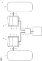
- Figure 1 shows the general setup of an apparatus according to the invention.
- an apparatus (1) for mixing two liquids with a static mixing device (2), having a first inlet (3) for receiving the first liquid (9), a second inlet (4) for receiving the second liquid (17), an outlet (5) for discharging the liquid mixture (product), a first feed module (6) for providing the first liquid (9) to the first inlet (3).
- the first feed module (6) comprises a substrate chamber (7) for holding a flexible container (8), a flexible container (8) with interior space holding the first liquid (9), a conduit (10) for providing fluid communication between the interior space of the flexible container (8) and the first inlet (3), a first pressure reservoir chamber (11) for holding a pressurised gas, a connector (12) for providing fluid communication between the pressure reservoir chamber (11) and the substrate chamber (7), with a valve (13) for reversibly interrupting the fluid communication.
- the apparatus further comprises a second feed module (14) for providing the second liquid (17) to the second inlet (4).
- the second feed module (14) comprises a second substrate chamber (15) for holding a second flexible container (16), a second flexible container (16) with interior space holding the second liquid (17), a conduit (18) for providing fluid communication between the interior space of the second flexible container (16) and the second inlet (4), a second pressure reservoir chamber (19) for holding a pressurised gas, a connector (20) for providing fluid communication between the second pressure reservoir chamber (19) and the second substrate chamber (15), with a means (21) for reversibly interrupting the fluid communication.
- Figure 3 shows a similar apparatus, further comprising means (24, 25) for indicating the pressure.
- the pressure reservoir chambers (11, 19) comprise inlets (29) for pressurised gas with means (22, 23) for closing the inlet (29).
- the means (22) for reversibly interrupting the fluid communication between second pressure reservoir chamber (19) and the second substrate chamber (15) is a three-way valve.
- Figure 4 depicts an example of a jet impingement reactor (31). It comprises a reaction chamber (36) defined by the interior surface (32) of the chamber wall (33) and is substantially spherical, except for the two fluid inlets (34) and the fluid outlet (37).
- the fluid inlets (34) are arranged at opposite positions on a first central axis (x) of the reaction chamber (36) and point at one another.
- Each of the fluid inlets (34) comprises a nozzle (35), which is a plain orifice nozzle in this embodiment.
- the fluid outlet (37) is positioned on a second central axis (y) which is perpendicular to the first central axis (x).
- the distance (d) between the two nozzles (35) is substantially the same as the diameter of the spherical reaction chamber (36).
- Figure 5 illustrates an optional type of a flexible container (40) holding a first or second liquid (41).
- a flexible container (40) with the same or a very similar design may also be useful as a container for receiving the third liquid.
- the flexible container (40) comprises an inlet (42) with a filtration means (43) such as a sterile filter to enable the aseptic introduction of the liquid (41).
- a part of the inlet (42) may be removed by thermal clamping, which closes and seals the remaining part of the inlet (42) and which may simultaneously remove the filtration means (43), prior to the introduction of the pre-filled flexible container (40) into a pressurisable substrate chamber.
- an outlet (44) is provided through which the liquid (41) may flow from the flexible container (40) to an inlet of the static mixing device.
- the downstream end of the outlet (44) exhibits a connecting piece (45) which may engage with a complementary connecting piece, e.g., to establish a fluid connection with the static mixing device.
- the container further has an identification means (46), such as an RFID code.
- FIG. 6 shows another version of the apparatus (1) similar to that of Fig. 2 , but with some further modifications.
- the flexible containers (8, 16) for the first and the second liquid (9, 17) have identification tags (46), such as RFID tags, and each of the first and the second substrate chamber (7, 15) has a sensor (47), such as an RFID reader, configured to read the identification tag.
- the flexible containers (8, 16) further comprise closed or sealed inlets (48), i.e. the structures that remain after melt sealing of the original inlets.
- the conduits between the flexible containers (8, 16) and the inlets (3, 4) of the static mixer (2) are arranged without valves.
- Engaged connecting pieces (45) are shown that help to ensure that a fluid connection between the flexible containers (8, 16) and the inlets (3, 4) is established or maintained.
- a container (30) for receiving the third fluid is depicted as a flexible container. The remaining features are the same as in Fig. 2 .
- Figure 7 depicts a further alternative version of the apparatus (1).
- the overall direction of liquid flow from the flexible containers (8, 16) in the pressurisable substrate chambers (7, 15) through the static mixing device (2) to the containers (30, 49) for receiving the third liquid is upwards, i.e. against gravity, or from a lower position to a higher position.
- the inlets (3, 4) of the static mixer (2) are higher than the outlets (10, 18) of the flexible containers (8, 16) that hold the first and the second liquid (9, 17).
- the orientation of the static mixer (2) itself is such that the outlet (5) is in a higher position than the inlets (3, 4), and the inlets of the containers (30, 49) for receiving the third liquid are in a higher position than the outlet (5) of the static mixer.
- the first container (30) for the third liquid which may serve as a product container, has been pre-filled with an amount of a liquid diluent.
- the second container (49) for the third liquid which may serve as a waste container, is also fluidically connected with the outlet (5) of the static mixer (2), like the first container (30).
- a means (28) for reversibly interrupting the fluid connection with the outlet (5) of the static mixer (2) is arranged for both the first container (30) and the second container (49).
- Figure 8 depicts another version of the apparatus (1).
- the second container (49) for receiving the third liquid which may function as a waste container already contains a portion of the third liquid, indicating that the mixing process, i.e. steps (dd) and (ee) according to the method of the invention, has already started.
- a means for inline particle size measurement of the third liquid comprising a sensing window (50) arranged downstream of, and in fluid connection with, the static mixing device (2), allowing the transmission of optical signals between the third liquid to an analyser (51) with a sensor capable of receiving such optical signals.
- the analyser (51) which is typically adapted for inline particle size measurement can communicate (e.g.
- controller (52) which is also in communication (e.g. electrically or wireless) with two means (28), such as pinch valves, for interrupting the fluid connection between the outlet (5) of the static mixing device (2) and the first (30) or second (49) container for receiving the third liquid, respectively.
- two means such as pinch valves
- the controller (52) By the action of the controller (52), those portions of the third liquid whose particle size as measured by the analyser (51) via the sensing window (50) do not comply with the desired particle size, can be directed to the second container (49), i.e. the waste container, in that the controller (52) operates the (e.g.) valves (28) to interrupt the fluid connection of the static mixer (2) to the first container (30) but not to the second container (49).
- the controller (52) can direct the third liquid into the first container (30), i.e. the product container, by operating the (e.g.) valves (28) to interrupt the fluid connection of the static mixer (2) to the second container (49) but not to the first container (30).
- the controller (52) can direct the third liquid into the first container (30), i.e. the product container, by operating the (e.g.) valves (28) to interrupt the fluid connection of the static mixer (2) to the second container (49) but not to the first container (30).
- Figure 9 shows a schematic illustration of a typical overall relationship between the pressure (P) in a pressure reservoir chamber, the pressure (P) in a corresponding pressurisable substrate chamber, and the flow rate (F) of a liquid as it is forced out from a flexible container accommodated in the substrate chamber over time (t) when conducting the method of the invention according to one embodiment.
- the figure is not to scale and only uses arbitrary units. Initially, i.e. before conducting step (dd) of the method, the pressure (101) in the pressure reservoir chamber which contains a pressurised gas is substantially higher than the pressure (102) in the corresponding pressurisable substrate chamber holding a flexible container with liquid.
- Step (dd) which may be initiated by changing the state of the means for reversibly interrupting the fluid communication between the pressure reservoir chamber and the substrate chamber from closed to open, which will cause an abrupt pressure equilibration (103) between the pressure reservoir chamber and the substrate chamber.
- this pressure equilibration involves an abrupt decrease of the pressure in the pressure reservoir chamber and an abrupt increase of the pressure in the corresponding substrate chamber, which is now above the ambient pressure level.
- the now increased pressure (104) in the substrate chamber i.e.
- the equilibrium pressure which acts on an external surface of the flexible container holding the liquid, now forces the liquid to flow out from the flexible container towards the static mixer at a substantially constant flow rate (105).
- no further pressurised gas is introduced to the pressure reservoir chamber or the substrate chamber.
- the pressure (104) in substrate chamber after equilibration remains nearly constant as the volume of the liquid flowing out from the flexible container is very small compared to the total volume of the pressure reservoir chamber and the substrate chamber.
- a minor decrease could, for example, result from the small increase of the volume of the pressurised gas in the substrate chamber, whereas a minor increase could result from a small temperature increase of the pressurised gas during the process.
- the minor pressure changes over time may also result in very minor changes in the flow rate, even though the flow rate ratio between the first and the second liquid remains substantially unaffected.
- the factors that could lead to a minor increase of the pressure (104) and of the flow rate (105) over time may also substantially compensate the effect of factors that could lead to a minor decrease of the pressure (104) and of the flow rate (105) over time such that the pressure (104) and the flow rate (105) remain substantially constant after the abrupt pressure equilibration.
- the non-optimised apparatus (non-optimised e.g. with respect to minimal dead volumes) comprised, as a static mixer, a jet impingement reactor as described in co-pending European patent application 21192535.9 .
- the substantially spherical reaction chamber had a diameter of 5 mm, and the first and the second inlet were each provided by a plain orifice nozzle having a pinhole diameter of 200 ⁇ m.
- Water was used as surrogate for the both first and the second liquid.
- the water was provided in two flexible containers, similar to infusion bags, and placed into the first and the second substrate chamber, respectively.
- the internal volume of the substrate chambers was approx. 10 L and the volume of water in each flexible container was approx.
- the apparatus was further equipped with flow meters (Cori-Flow TM ) arranged in fluid conduits between the interior space of the flexible containers and the first or the second inlet of the jet impingement reactor, respectively, and with various pressure sensors.
- flow meters Cori-Flow TM
- Pressure equilibration immediately triggered the flow of water out of the flexible containers in the substrate chambers in a downstream direction, i.e. towards and through the jet impingement reactor.
- the flow rates were rather constant starting from about two seconds after the initial pressure equilibration:
- the flow rate in the first feed module increased only very slightly and evenly from about 53 to about 54 mL/min, and in the second feed module from about 54 to about 55 mL/min.
- a flow rate peak was observed which was considered an artifact caused by the initial pressure impulse traveling through the water-filled system.
- the very minor difference between the two feed modules is likely to be caused by minimal pinhole differences due to manufacturing tolerance, whereas the slight and technically rather negligible increase of the flow rates over time may result from the corresponding increase in pressure.
- the experiment demonstrates that the apparatus is suitable to achieve an almost instant onset of flow of two liquids from flexible substrate containers into a static mixing device followed by highly controlled flow rates and flow rate ratios between the flow rates. It also demonstrates that small-scale mixing of two liquids without pumps may be performed using the apparatus.
- Example 2 A similar prototype apparatus as in Example 1 was used for mixing two model liquids which upon mixing lead to the formation of solid barium sulphate particles, except that the reaction chamber of the jet impingement reactor had a diameter of 3 mm.
- the first liquid consisted of about 500 mL of an aqueous solution of barium chloride, and the second liquid was about 500 mL of an aqueous solution of barium sulphate.
- the two liquids were provided in flexible bags which were placed into a first and a second substrate chamber having a volume of about 10 L, respectively.
- the first pressure reservoir chamber had a volume of 20 L and was filled with pressurised air up to a pressure of 10.9 bar.
- the second pressure reservoir chamber also had a volume of 20 L and was pressurised with air to 6.1 bar.
- Connectors between the first pressure reservoir chamber and the first substrate chamber and between the second pressure reservoir chamber and the second substrate chamber were equipped with solenoid valves. Upon simultaneously opening the valves, substantially instant pressure equilibration between each pressure reservoir chamber and the therewith connected substrate chamber was observed: For the first feed module (i.e. with the first pressure reservoir chamber and the first substrate chamber), a pressure of 7.2 bar was recorded, for the second feed module (i.e. with the second pressure reservoir chamber and the second substrate chamber), the pressure was 4.6 bar. The overpressure caused the two liquids to flow from the respective flexible containers at a total flow rate (i.e.
- the liquid product (i.e. the third liquid) resulting from the mixing of the first and the second liquid in the jet impingement reactor was an aqueous dispersion of barium sulphate nanoparticles having a z-average particle size of 79.4 nm and a polydispersity index of 0.14, as measured by dynamic light scattering (DLS) using a Anton Paar TM Litesizer 500.
Landscapes
- Chemical & Material Sciences (AREA)
- Chemical Kinetics & Catalysis (AREA)
- Engineering & Computer Science (AREA)
- General Engineering & Computer Science (AREA)
- Software Systems (AREA)
- Dispersion Chemistry (AREA)
- Accessories For Mixers (AREA)
- Package Specialized In Special Use (AREA)
- Apparatus Associated With Microorganisms And Enzymes (AREA)
- Manufacturing Of Micro-Capsules (AREA)
- Mixers With Rotating Receptacles And Mixers With Vibration Mechanisms (AREA)
Claims (15)
- Appareil (1) destiné à mélanger un premier liquide et un deuxième liquide, ledit appareil comprenant :(a) un mélangeur statique (2) comportant- une première entrée (3) destinée à recevoir le premier liquide,- une deuxième entrée (4) destinée à recevoir le deuxième liquide,
et- une sortie (5) destinée à évacuer un troisième liquide qui résulte du mélange du premier liquide et du deuxième liquide ;(b) un premier module d'alimentation (6, 14) destiné à fournir le premier liquide à la première entrée ;(c) un deuxième module d'alimentation (6, 14) destiné à fournir le deuxième liquide à la deuxième entrée ;
chacun des premier et deuxième modules d'alimentation (6, 14) comprenant :- une chambre de substrat (7, 15) destinée à contenir un récipient souple (8, 16, 40), ledit récipient souple comportant un espace intérieur destiné à contenir respectivement le premier liquide ou le deuxième liquide ;- un conduit (10, 18) destiné à assurer une communication fluidique entre l'espace intérieur du récipient souple et la première ou la deuxième entrée du mélangeur statique, respectivement ;- une chambre de réservoir sous pression (11, 19) destinée à contenir un gaz sous pression ;- un connecteur (12, 20) destiné à assurer une communication fluidique entre la chambre de réservoir sous pression (11, 19) et la chambre de substrat (7, 15), ladite communication fluidique étant destinée à permettre un écoulement de gaz sous pression de la chambre de réservoir sous pression (11, 19) à la chambre de substrat (7, 15) de manière à exercer une pression sur une surface externe du récipient souple (8, 16, 40) et à forcer le premier ou le deuxième liquide depuis le récipient jusque dans le conduit ;- un moyen (21) destiné à interrompre de manière réversible la communication fluidique entre la chambre de réservoir sous pression (11, 19) et la chambre de substrat (7, 15), ledit moyen (21) présentant un état ouvert et un état fermé ;
caractérisé en ce que
le connecteur (12, 20) et ledit moyen (21) sont agencés de manière à réaliser un équilibrage de pression immédiat en moins de 2 secondes entre la chambre de réservoir sous pression (11, 19) et la chambre substrat (7, 15) lors du changement d'état dudit moyen (21) de fermé à ouvert. - Appareil selon la revendication 1, le mélangeur statique (2) comprenant un mélangeur en T, un mélangeur en Y, un mélangeur à vortex, un mélangeur statique à chicane, un dispositif de mélange micro-fluidique, un mélangeur à vortex à entrées multiples (MIVM) ou un réacteur à jet d'impact; éventuellement le mélangeur statique (2) étant en verre ou en matière synthétique.
- Appareil selon l'une quelconque des revendications précédentes, la chambre de réservoir sous pression (11, 19) ayant un volume plus grand que la chambre de substrat (7, 15) avec laquelle elle est en communication fluidique ; éventuellement le rapport du volume de la chambre de réservoir sous pression (11, 19) au volume de la chambre de substrat (7, 15) étant d'au moins environ 10, et éventuellement dans la gamme allant d'environ 10 à environ 100, par exemple d'environ 20 à environ 50.
- Appareil selon l'une quelconque des revendications précédentes,l'état ouvert et l'état fermé étant les seuls états du moyen (21) destiné à d'interrompre de manière réversible la communication fluidique entre la chambre de réservoir sous pression (11, 19) et la chambre de substrat (7, 15) ; et/oule moyen destiné à interrompre de manière réversible la communication fluidique entre la chambre de réservoir sous pression (11, 19) et la chambre de substrat (7, 15) dans son état ouvert présentant un trajet de fluide qui est destiné au gaz sous pression et dont la section transversale est d'au moins environ 1 mm2.
- Appareil selon l'une quelconque des revendications précédentes, le connecteur (12, 20) et le moyen (21) destiné à interrompre de manière réversible la communication fluidique entre la chambre de réservoir sous pression (11, 19) et la chambre de substrat (7, 15) ne comprenant aucun élément de régulation de pression ; et/ou le moyen (21) destiné à interrompre de manière réversible la communication fluidique entre la chambre de réservoir sous pression (11, 19) et la chambre de substrat (7, 15) étant le seul moyen destiné à commander le flux de gaz sous pression entre la chambre de réservoir sous pression (11, 19) et la chambre de substrat respective (7, 15).
- Appareil selon l'une quelconque des revendications précédentes, la chambre de substrat (7, 15) du premier et/ou deuxième module d'alimentation (6, 14) comprenant un moyen destiné à être ouvert et fermé de manière à permettre une insertion ou un retrait du récipient souple respectif (8, 16, 40).
- Appareil selon l'une quelconque des revendications précédentes, le conduit destiné à assurer une communication fluidique entre l'espace intérieur du récipient souple et la première ou deuxième entrée du mélangeur statique comprenant une extrémité amont reliée au récipient souple et une extrémité aval reliée à la première ou deuxième entrée du mélangeur statique, l'extrémité aval étant dans une position plus haute que l'extrémité amont; et/ou le mélangeur statique étant orienté de telle sorte que sa sortie soit dans une position plus haute que sa première et deuxième entrée.
- Appareil selon l'une quelconque des revendications précédentes, la sortie du mélangeur statique pouvant être reliée fluidiquement à un premier récipient destiné à recevoir le troisième liquide ; éventuellement :- ledit premier récipient étant un récipient souple ; et/ou- l'appareil comprenant en outre un moyen destiné à interrompre de manière réversible la liaison fluidique entre la sortie du mélangeur statique et le premier récipient destiné à recevoir le troisième liquide ; et/ou- ledit premier récipient destiné à recevoir le troisième liquide comprenant une première et une deuxième entrée de fluide,- la première entrée de fluide pouvant être reliée à la sortie du mélangeur statique, et- la deuxième entrée de fluide étant adaptée pour remplir ledit premier récipient avec une quantité d'un diluant liquide ; et/ou- ledit premier récipient destiné à recevoir le troisième liquide étant dans une position plus haute que la sortie du mélangeur statique ; et/ou- ledit premier récipient comprenant une sortie destinée à retirer le troisième liquide ou un mélange du troisième liquide et du diluant liquide.
- Appareil selon la revendication 8, la sortie du mélangeur statique pouvant être reliée fluidiquement à un deuxième récipient destiné à recevoir le troisième liquide, éventuellement :- ledit deuxième récipient étant un récipient souple ; et/ou- l'appareil comprenant en outre un moyen destiné à interrompre de manière réversible la liaison fluidique entre la sortie du mélangeur statique et le deuxième récipient destiné à recevoir le troisième liquide ; et/ou- ledit deuxième récipient destiné à recevoir le troisième liquide étant dans une position plus haute que la sortie du mélangeur statique.
- Appareil selon l'une quelconque des revendications précédentes, le mélangeur statique étant un réacteur à jet d'impact (31) qui comporte une chambre de mélange (36) définie par une surface intérieure d'une paroi de chambre de mélange (32), la chambre de mélange (36) ayant une forme générale sensiblement sphéroïdale, la chambre de mélange comprenant de préférence :- une première et une deuxième entrée de fluide (34), la première et la deuxième entrée de fluide étant disposées à des positions opposées sur un premier axe central (x) de la chambre de réaction de manière à pointer l'une vers l'autre, et chacune des première et deuxième entrées de fluide comprenant une buse (35) ; et- une sortie de fluide (37) disposée à une troisième position, ladite troisième position étant située sur un deuxième axe central (y) de ladite chambre, le deuxième axe central étant perpendiculaire au premier axe central (x) ; etla distance entre la buse de la première entrée de fluide et la buse de la deuxième entrée de fluide étant inférieure ou égale au diamètre (d) de la chambre de mélange le long du premier axe central (x).
- Procédé de mélange d'un premier liquide et d'un deuxième liquide, ledit procédé comprenant les étapes suivantes :(aa) fournir un premier récipient souple (8, 16, 40) contenant le premier liquide, ledit premier récipient souple étant logé dans une première chambre de substrat (7, 15) pouvant être mise sous pression ;(bb) fournir un deuxième récipient souple (8, 16, 40) contenant le deuxième liquide, ledit deuxième récipient souple étant logé dans une deuxième chambre de substrat (7, 15) pouvant être mise sous pression ;(cc) fournir un mélangeur statique (2) comportant- une première entrée (3) destinée à recevoir le premier liquide,- une deuxième entrée (4) destinée à recevoir le deuxième liquide,
et- une sortie (5) destinée à évacuer un troisième liquide qui résulte du mélange du premier liquide et du deuxième liquide ; et(dd) mettre sous pression la première et la deuxième chambre de substrat, pouvant être mise sous pression, indépendamment au moyen d'un gaz sous pression qui exerce une pression sur une surface externe respectivement de la première et de la deuxième chambre de substrat pouvant être mise sous pression de manière à forcer ledit premier et ledit deuxième liquide à travers le mélangeur statique afin de mélanger ledit premier et ledit deuxième liquide ; et(ee) recueillir le troisième liquide ;
un appareil (1) comprenant le premier récipient souple logé dans la première chambre de substrat pouvant être mise sous pression, le deuxième récipient souple logé dans la deuxièmee chambre de substrat pouvant être mise sous pression et le mélangeur statique et étant utilisé, selon l'une quelconque des revendications précédentes 1 à 10, pour le mélange des liquides. - Procédé selon la revendication 11, l'étape de mise sous pression (dd) incluant une augmentation soudaine de la pression dans chacune des première et deuxième chambres de substrat, pouvant être mises sous pression, depuis une pression initiale à une pression de traitement maximale en moins de 2 secondes, et de préférence en moins d'environ 1 seconde ; la pression initiale étant approximativement la pression ambiante et la pression de traitement maximale étant dans la gamme allant d'environ 1 à 16 bars, et de préférence dans la gamme allant d'environ 2 à 12 bars.
- Procédé selon la revendication 11 ou 12, chacune des première et deuxième chambres de substrat pouvant être mises sous pression étant reliée à une première et une deuxième chambres de réservoir sous pression destinées à contenir le gaz sous pression au moyen d'un connecteur destiné à assurer une communication fluidique entre la chambre de réservoir sous pression respective et la chambre de substrat respective pouvant être mise sous pression, un moyen destiné à interrompre de manière réversible la communication fluidique entre chaque chambre de réservoir sous pression et la chambre de substrat respective pouvant être mise sous pression étant prévu, ledit moyen présentant un état ouvert et un état fermé ; avant de réaliser l'étape de mise sous pression (dd) :- la chambre de réservoir sous pression respective étant dans un état sous pression tel que sa pression est environ 2 à 20 fois supérieure à la pression de la chambre de substrat respective pouvant être mise sous pression, et- le moyen destiné à interrompre de manière réversible la communication fluidique entre la chambre de réservoir sous pression respective et la chambre de substrat respective pouvant être mise sous pression étant dans l'état fermé.
- Procédé selon l'une quelconque des revendications 11 à 13,- le premier liquide comprenant une solution organique d'un ou plusieurs lipides ;- le deuxième liquide comprenant une solution aqueuse d'un agent biologiquement actif; et- des nanoparticules lipidiques étant formées par le mélange du premier et du deuxième liquide ;
l'agent biologiquement actif étant associé aux nanoparticules lipidiques et/ou encapsulé dans celles-ci ; éventuellement l'agent biologiquement actif étant un oligonucléotide ou un polynucléotide ; en outre éventuellement l'oligonucléotide ou le polynucléotide étant une molécule d'ARNm éventuellement modifiée qui comprend une séquence d'acide nucléique codant un antigène, en particulier un antigène tumoral, un antigène viral, un antigène bactérien, un antigène fongique ou un antigène protozoaire. - Utilisation d'un gaz sous pression pour forcer un premier liquide à s'écouler depuis un récipient souple (8, 16, 40) jusque dans un mélangeur statique (2) où ledit liquide est mélangé à un deuxième liquide de manière à former un troisième liquide, ledit gaz sous pression étant fourni de manière à exercer brusquement une pression de 1 à 16 bars sur une surface externe dudit récipient souple (8, 16, 40) sans être en communication fluidique avec ledit premier liquide, le mélangeur statique (2) faisant partie d'un appareil (1) tel que défini dans l'une quelconque des revendications 1 à 10, et l'utilisation impliquant un procédé tel que défini dans l'une quelconque des revendications 11 à 14.
Priority Applications (1)
| Application Number | Priority Date | Filing Date | Title |
|---|---|---|---|
| EP25171632.0A EP4582176A3 (fr) | 2021-11-03 | 2022-11-03 | Appareil pour mélanger de petits volumes de liquide |
Applications Claiming Priority (4)
| Application Number | Priority Date | Filing Date | Title |
|---|---|---|---|
| EP21206216 | 2021-11-03 | ||
| EP22157837 | 2022-02-21 | ||
| EP22183341 | 2022-07-06 | ||
| PCT/EP2022/080743 WO2023079039A1 (fr) | 2021-11-03 | 2022-11-03 | Appareil et procédé pour mélanger de petits volumes de liquide, et utilisation de l'appareil |
Related Child Applications (1)
| Application Number | Title | Priority Date | Filing Date |
|---|---|---|---|
| EP25171632.0A Division EP4582176A3 (fr) | 2021-11-03 | 2022-11-03 | Appareil pour mélanger de petits volumes de liquide |
Publications (3)
| Publication Number | Publication Date |
|---|---|
| EP4247529A1 EP4247529A1 (fr) | 2023-09-27 |
| EP4247529C0 EP4247529C0 (fr) | 2025-04-23 |
| EP4247529B1 true EP4247529B1 (fr) | 2025-04-23 |
Family
ID=84363050
Family Applications (2)
| Application Number | Title | Priority Date | Filing Date |
|---|---|---|---|
| EP22813250.2A Active EP4247529B1 (fr) | 2021-11-03 | 2022-11-03 | Appareil et procédé de mélange de petits volumes de liquide, et utilisation de l'appareil |
| EP25171632.0A Pending EP4582176A3 (fr) | 2021-11-03 | 2022-11-03 | Appareil pour mélanger de petits volumes de liquide |
Family Applications After (1)
| Application Number | Title | Priority Date | Filing Date |
|---|---|---|---|
| EP25171632.0A Pending EP4582176A3 (fr) | 2021-11-03 | 2022-11-03 | Appareil pour mélanger de petits volumes de liquide |
Country Status (8)
| Country | Link |
|---|---|
| EP (2) | EP4247529B1 (fr) |
| JP (1) | JP2024543826A (fr) |
| KR (1) | KR20240116908A (fr) |
| AU (1) | AU2022381525A1 (fr) |
| CA (1) | CA3237294A1 (fr) |
| ES (1) | ES3025099T3 (fr) |
| PL (1) | PL4247529T3 (fr) |
| WO (1) | WO2023079039A1 (fr) |
Families Citing this family (3)
| Publication number | Priority date | Publication date | Assignee | Title |
|---|---|---|---|---|
| KR20250069574A (ko) | 2022-09-12 | 2025-05-19 | 레온-나노드럭스 게엠베하 | 두 액체 혼합용 일회용 반응기 |
| JP2025531451A (ja) | 2022-09-30 | 2025-09-19 | レオン-ナノドラッグス ゲーエムベーハー | 無菌混合プロセスのためのカセットシステム |
| CN119507914B (zh) * | 2024-10-29 | 2025-10-21 | 河南理工大学 | 一种煤层增透用纳米流体与活性剂联合注入装置 |
Family Cites Families (6)
| Publication number | Priority date | Publication date | Assignee | Title |
|---|---|---|---|---|
| GB9000753D0 (en) * | 1990-01-12 | 1990-03-14 | Harper Alan | Positive displacement device |
| WO2000029103A1 (fr) | 1998-11-13 | 2000-05-25 | Optime Therapeutics, Inc. | Procede et dispositif de production de liposomes |
| FR2856940B1 (fr) | 2003-07-04 | 2007-02-09 | Stedim Sa | Systeme clos a usage unique de melange, de stockage et d'homogeneisation de liquides en conditions propres ou steriles |
| WO2009076276A2 (fr) * | 2007-12-06 | 2009-06-18 | Advanced Technology Materials, Inc. | Systèmes et procédés pour la délivrance de combinaisons de matériaux de traitement contenant du fluide |
| CN102791383B (zh) * | 2010-01-06 | 2017-11-14 | 恩特格里斯公司 | 具有除气和感测能力的液体分配系统 |
| CA3075827C (fr) * | 2018-06-22 | 2021-11-16 | Delphi Scientific, Llc | Appareil, systemes et procedes de fabrication en continu de nanomateriaux et de produits chimiques de haute purete |
-
2022
- 2022-11-03 EP EP22813250.2A patent/EP4247529B1/fr active Active
- 2022-11-03 EP EP25171632.0A patent/EP4582176A3/fr active Pending
- 2022-11-03 ES ES22813250T patent/ES3025099T3/es active Active
- 2022-11-03 CA CA3237294A patent/CA3237294A1/fr active Pending
- 2022-11-03 KR KR1020247018538A patent/KR20240116908A/ko active Pending
- 2022-11-03 WO PCT/EP2022/080743 patent/WO2023079039A1/fr not_active Ceased
- 2022-11-03 JP JP2024526757A patent/JP2024543826A/ja active Pending
- 2022-11-03 AU AU2022381525A patent/AU2022381525A1/en active Pending
- 2022-11-03 PL PL22813250.2T patent/PL4247529T3/pl unknown
Also Published As
| Publication number | Publication date |
|---|---|
| WO2023079039A1 (fr) | 2023-05-11 |
| CA3237294A1 (fr) | 2023-05-11 |
| ES3025099T3 (en) | 2025-06-06 |
| PL4247529T3 (pl) | 2025-08-25 |
| AU2022381525A1 (en) | 2024-06-20 |
| EP4582176A2 (fr) | 2025-07-09 |
| EP4247529C0 (fr) | 2025-04-23 |
| EP4582176A3 (fr) | 2025-10-15 |
| JP2024543826A (ja) | 2024-11-26 |
| EP4247529A1 (fr) | 2023-09-27 |
| KR20240116908A (ko) | 2024-07-30 |
Similar Documents
| Publication | Publication Date | Title |
|---|---|---|
| EP4247529B1 (fr) | Appareil et procédé de mélange de petits volumes de liquide, et utilisation de l'appareil | |
| EP2338478B1 (fr) | Méthode de préparation de liposomes | |
| US20080171078A1 (en) | Uniformly sized liposomes | |
| JP4937764B2 (ja) | 液体分与システム用の混合を促進させるリザーバ | |
| US7985058B2 (en) | Method and apparatus for making uniformly sized particles | |
| EP4526027B1 (fr) | Appareil et procédé pour actionner un dispositif de mélange statique | |
| EA022725B1 (ru) | Флакон для жидкости с раздаточной головкой для покапельной раздачи | |
| US20230330618A1 (en) | Flow channel structure, method for agitating fluid and method for manufacturing lipid particles | |
| US20230219090A1 (en) | Flow channel structure for removing foreign substance, method for removing foreign substance, and method for manufacturing lipid particles | |
| US20240299653A1 (en) | A Cartridge for Mixing a Liquid Intended for Intracorporeal Use | |
| CN118541208A (zh) | 用于混合小液体体积的设备和方法以及该设备的用途 | |
| HK40116872A (zh) | 用於混合小液体体积的设备和方法以及该设备的用途 | |
| EP4021533B1 (fr) | Cartouche pour mélanger un liquide destiné à une utilisation intracorporelle | |
| WO2024057580A1 (fr) | Structure de canal d'écoulement et procédé de production de particule lipidique | |
| KR20250080871A (ko) | 무균 혼합 공정용 카세트 시스템 | |
| CN116897055A (zh) | 用于混合旨在用于体内使用的磷脂组合物的筒 | |
| EP3785792A1 (fr) | Cartouche pour mélanger un liquide destiné à une utilisation intracorporelle | |
| CN116635078A (zh) | 用于制备含有脂质体的液体的方法和装置以及制备的液体 | |
| KR20250071197A (ko) | 원심력을 이용한 디스크 기반 지질 나노입자 제조용 미세유체 플랫폼 및 이를 이용한 방법 |
Legal Events
| Date | Code | Title | Description |
|---|---|---|---|
| STAA | Information on the status of an ep patent application or granted ep patent |
Free format text: STATUS: UNKNOWN |
|
| STAA | Information on the status of an ep patent application or granted ep patent |
Free format text: STATUS: THE INTERNATIONAL PUBLICATION HAS BEEN MADE |
|
| PUAI | Public reference made under article 153(3) epc to a published international application that has entered the european phase |
Free format text: ORIGINAL CODE: 0009012 |
|
| STAA | Information on the status of an ep patent application or granted ep patent |
Free format text: STATUS: REQUEST FOR EXAMINATION WAS MADE |
|
| 17P | Request for examination filed |
Effective date: 20230620 |
|
| AK | Designated contracting states |
Kind code of ref document: A1 Designated state(s): AL AT BE BG CH CY CZ DE DK EE ES FI FR GB GR HR HU IE IS IT LI LT LU LV MC ME MK MT NL NO PL PT RO RS SE SI SK SM TR |
|
| STAA | Information on the status of an ep patent application or granted ep patent |
Free format text: STATUS: EXAMINATION IS IN PROGRESS |
|
| 17Q | First examination report despatched |
Effective date: 20231129 |
|
| RAP3 | Party data changed (applicant data changed or rights of an application transferred) |
Owner name: LEON-NANODRUGS GMBH |
|
| GRAP | Despatch of communication of intention to grant a patent |
Free format text: ORIGINAL CODE: EPIDOSNIGR1 |
|
| STAA | Information on the status of an ep patent application or granted ep patent |
Free format text: STATUS: GRANT OF PATENT IS INTENDED |
|
| INTG | Intention to grant announced |
Effective date: 20241118 |
|
| RIN1 | Information on inventor provided before grant (corrected) |
Inventor name: STIENEKER, FRANK |
|
| DAV | Request for validation of the european patent (deleted) | ||
| DAX | Request for extension of the european patent (deleted) | ||
| GRAS | Grant fee paid |
Free format text: ORIGINAL CODE: EPIDOSNIGR3 |
|
| GRAA | (expected) grant |
Free format text: ORIGINAL CODE: 0009210 |
|
| STAA | Information on the status of an ep patent application or granted ep patent |
Free format text: STATUS: THE PATENT HAS BEEN GRANTED |
|
| AK | Designated contracting states |
Kind code of ref document: B1 Designated state(s): AL AT BE BG CH CY CZ DE DK EE ES FI FR GB GR HR HU IE IS IT LI LT LU LV MC ME MK MT NL NO PL PT RO RS SE SI SK SM TR |
|
| REG | Reference to a national code |
Ref country code: GB Ref legal event code: FG4D |
|
| REG | Reference to a national code |
Ref country code: CH Ref legal event code: EP |
|
| REG | Reference to a national code |
Ref country code: DE Ref legal event code: R096 Ref document number: 602022013693 Country of ref document: DE |
|
| REG | Reference to a national code |
Ref country code: IE Ref legal event code: FG4D |
|
| U01 | Request for unitary effect filed |
Effective date: 20250429 |
|
| U07 | Unitary effect registered |
Designated state(s): AT BE BG DE DK EE FI FR IT LT LU LV MT NL PT RO SE SI Effective date: 20250507 |
|
| REG | Reference to a national code |
Ref country code: ES Ref legal event code: FG2A Ref document number: 3025099 Country of ref document: ES Kind code of ref document: T3 Effective date: 20250606 |
|
| PG25 | Lapsed in a contracting state [announced via postgrant information from national office to epo] |
Ref country code: NO Free format text: LAPSE BECAUSE OF FAILURE TO SUBMIT A TRANSLATION OF THE DESCRIPTION OR TO PAY THE FEE WITHIN THE PRESCRIBED TIME-LIMIT Effective date: 20250723 Ref country code: GR Free format text: LAPSE BECAUSE OF FAILURE TO SUBMIT A TRANSLATION OF THE DESCRIPTION OR TO PAY THE FEE WITHIN THE PRESCRIBED TIME-LIMIT Effective date: 20250724 |
|
| PG25 | Lapsed in a contracting state [announced via postgrant information from national office to epo] |
Ref country code: HR Free format text: LAPSE BECAUSE OF FAILURE TO SUBMIT A TRANSLATION OF THE DESCRIPTION OR TO PAY THE FEE WITHIN THE PRESCRIBED TIME-LIMIT Effective date: 20250423 |
|
| PG25 | Lapsed in a contracting state [announced via postgrant information from national office to epo] |
Ref country code: RS Free format text: LAPSE BECAUSE OF FAILURE TO SUBMIT A TRANSLATION OF THE DESCRIPTION OR TO PAY THE FEE WITHIN THE PRESCRIBED TIME-LIMIT Effective date: 20250723 |
|
| PG25 | Lapsed in a contracting state [announced via postgrant information from national office to epo] |
Ref country code: IS Free format text: LAPSE BECAUSE OF FAILURE TO SUBMIT A TRANSLATION OF THE DESCRIPTION OR TO PAY THE FEE WITHIN THE PRESCRIBED TIME-LIMIT Effective date: 20250823 |
|
| REG | Reference to a national code |
Ref country code: CH Ref legal event code: U11 Free format text: ST27 STATUS EVENT CODE: U-0-0-U10-U11 (AS PROVIDED BY THE NATIONAL OFFICE) Effective date: 20251201 |
|
| U20 | Renewal fee for the european patent with unitary effect paid |
Year of fee payment: 4 Effective date: 20251201 |
|
| PG25 | Lapsed in a contracting state [announced via postgrant information from national office to epo] |
Ref country code: SM Free format text: LAPSE BECAUSE OF FAILURE TO SUBMIT A TRANSLATION OF THE DESCRIPTION OR TO PAY THE FEE WITHIN THE PRESCRIBED TIME-LIMIT Effective date: 20250423 |
|
| PGFP | Annual fee paid to national office [announced via postgrant information from national office to epo] |
Ref country code: CH Payment date: 20251201 Year of fee payment: 4 |
|
| PG25 | Lapsed in a contracting state [announced via postgrant information from national office to epo] |
Ref country code: CZ Free format text: LAPSE BECAUSE OF FAILURE TO SUBMIT A TRANSLATION OF THE DESCRIPTION OR TO PAY THE FEE WITHIN THE PRESCRIBED TIME-LIMIT Effective date: 20250423 |
|
| PGFP | Annual fee paid to national office [announced via postgrant information from national office to epo] |
Ref country code: IE Payment date: 20251121 Year of fee payment: 4 |
|
| PGFP | Annual fee paid to national office [announced via postgrant information from national office to epo] |
Ref country code: PL Payment date: 20251024 Year of fee payment: 4 |
|
| PG25 | Lapsed in a contracting state [announced via postgrant information from national office to epo] |
Ref country code: SK Free format text: LAPSE BECAUSE OF FAILURE TO SUBMIT A TRANSLATION OF THE DESCRIPTION OR TO PAY THE FEE WITHIN THE PRESCRIBED TIME-LIMIT Effective date: 20250423 |
|
| PGFP | Annual fee paid to national office [announced via postgrant information from national office to epo] |
Ref country code: ES Payment date: 20251229 Year of fee payment: 4 |
|
| PLBE | No opposition filed within time limit |
Free format text: ORIGINAL CODE: 0009261 |
|
| STAA | Information on the status of an ep patent application or granted ep patent |
Free format text: STATUS: NO OPPOSITION FILED WITHIN TIME LIMIT |
|
| REG | Reference to a national code |
Ref country code: CH Ref legal event code: L10 Free format text: ST27 STATUS EVENT CODE: U-0-0-L10-L00 (AS PROVIDED BY THE NATIONAL OFFICE) Effective date: 20260304 |
|
| 26N | No opposition filed |
Effective date: 20260126 |