EP4249637A1 - Procédé d'évaluation accélérée d'anode - Google Patents
Procédé d'évaluation accélérée d'anode Download PDFInfo
- Publication number
- EP4249637A1 EP4249637A1 EP21894701.8A EP21894701A EP4249637A1 EP 4249637 A1 EP4249637 A1 EP 4249637A1 EP 21894701 A EP21894701 A EP 21894701A EP 4249637 A1 EP4249637 A1 EP 4249637A1
- Authority
- EP
- European Patent Office
- Prior art keywords
- anode
- potential
- accelerated
- evaluation method
- duration
- Prior art date
- Legal status (The legal status is an assumption and is not a legal conclusion. Google has not performed a legal analysis and makes no representation as to the accuracy of the status listed.)
- Pending
Links
Images



Classifications
-
- G—PHYSICS
- G01—MEASURING; TESTING
- G01N—INVESTIGATING OR ANALYSING MATERIALS BY DETERMINING THEIR CHEMICAL OR PHYSICAL PROPERTIES
- G01N27/00—Investigating or analysing materials by the use of electric, electrochemical, or magnetic means
- G01N27/26—Investigating or analysing materials by the use of electric, electrochemical, or magnetic means by investigating electrochemical variables; by using electrolysis or electrophoresis
- G01N27/416—Systems
- G01N27/48—Systems using polarography, i.e. measuring changes in current under a slowly-varying voltage
-
- C—CHEMISTRY; METALLURGY
- C25—ELECTROLYTIC OR ELECTROPHORETIC PROCESSES; APPARATUS THEREFOR
- C25B—ELECTROLYTIC OR ELECTROPHORETIC PROCESSES FOR THE PRODUCTION OF COMPOUNDS OR NON-METALS; APPARATUS THEREFOR
- C25B1/00—Electrolytic production of inorganic compounds or non-metals
- C25B1/01—Products
- C25B1/02—Hydrogen or oxygen
- C25B1/04—Hydrogen or oxygen by electrolysis of water
-
- C—CHEMISTRY; METALLURGY
- C25—ELECTROLYTIC OR ELECTROPHORETIC PROCESSES; APPARATUS THEREFOR
- C25B—ELECTROLYTIC OR ELECTROPHORETIC PROCESSES FOR THE PRODUCTION OF COMPOUNDS OR NON-METALS; APPARATUS THEREFOR
- C25B15/00—Operating or servicing cells
-
- C—CHEMISTRY; METALLURGY
- C25—ELECTROLYTIC OR ELECTROPHORETIC PROCESSES; APPARATUS THEREFOR
- C25B—ELECTROLYTIC OR ELECTROPHORETIC PROCESSES FOR THE PRODUCTION OF COMPOUNDS OR NON-METALS; APPARATUS THEREFOR
- C25B11/00—Electrodes; Manufacture thereof not otherwise provided for
-
- Y—GENERAL TAGGING OF NEW TECHNOLOGICAL DEVELOPMENTS; GENERAL TAGGING OF CROSS-SECTIONAL TECHNOLOGIES SPANNING OVER SEVERAL SECTIONS OF THE IPC; TECHNICAL SUBJECTS COVERED BY FORMER USPC CROSS-REFERENCE ART COLLECTIONS [XRACs] AND DIGESTS
- Y02—TECHNOLOGIES OR APPLICATIONS FOR MITIGATION OR ADAPTATION AGAINST CLIMATE CHANGE
- Y02E—REDUCTION OF GREENHOUSE GAS [GHG] EMISSIONS, RELATED TO ENERGY GENERATION, TRANSMISSION OR DISTRIBUTION
- Y02E60/00—Enabling technologies; Technologies with a potential or indirect contribution to GHG emissions mitigation
- Y02E60/30—Hydrogen technology
- Y02E60/36—Hydrogen production from non-carbon containing sources, e.g. by water electrolysis
-
- Y—GENERAL TAGGING OF NEW TECHNOLOGICAL DEVELOPMENTS; GENERAL TAGGING OF CROSS-SECTIONAL TECHNOLOGIES SPANNING OVER SEVERAL SECTIONS OF THE IPC; TECHNICAL SUBJECTS COVERED BY FORMER USPC CROSS-REFERENCE ART COLLECTIONS [XRACs] AND DIGESTS
- Y02—TECHNOLOGIES OR APPLICATIONS FOR MITIGATION OR ADAPTATION AGAINST CLIMATE CHANGE
- Y02P—CLIMATE CHANGE MITIGATION TECHNOLOGIES IN THE PRODUCTION OR PROCESSING OF GOODS
- Y02P20/00—Technologies relating to chemical industry
- Y02P20/10—Process efficiency
- Y02P20/133—Renewable energy sources, e.g. sunlight
Definitions
- the present invention relates to an accelerated evaluation method for an anode to be used in, for example, water electrolysis.
- Hydrogen is secondary energy which is suitable for storage and transportation and has small environmental load, and therefore a hydrogen energy system using hydrogen as an energy carrier has been attracting attention.
- hydrogen is mainly produced by steam reforming of fossil fuel, or the like.
- water electrolysis using renewable energy, such as solar power generation and wind power generation, is important in generic technology. Water electrolysis is low cost, suitable for enlargement of scale, and therefore is a predominant technique for hydrogen production.
- alkaline water electrolysis in which a high-concentration alkali aqueous solution is used for an electrolyte.
- solid polymer electrolyte water electrolysis in which a solid polymer electrolyte (SPE) membrane is used for an electrolyte.
- SPE solid polymer electrolyte
- alkaline water electrolysis in which an inexpensive material, such as an iron group metal including nickel and the like, is used, is more suitable than solid polymer electrolyte water electrolysis, in which an electrode using a large amount of an expensive noble metal is used.
- an anion exchange membrane has also progressed.
- An electrode material which is the same one as used in alkaline water electrolysis can also be used in water electrolysis using an anion exchange membrane.
- the upper limit of the operation temperature is controlled to about 80 to about 90°C.
- the electrolysis performance has been improved to about 1.7 to about 1.9 V (78 to 87% in terms of efficiency) at a current density of 0.3 to 0.4 A ⁇ cm -2 by the development of constitutional materials and various piping materials for an electrolytic cell, which are high-temperature resistant and resistant to a high-concentration alkali aqueous solution, and the development of a low-resistivity separator and an electrode which has an enlarged surface area and has a catalyst applied thereon.
- a nickel-based material which is stable in a high-concentration alkali aqueous solution is used as an alkaline water electrolysis anode, and it has been known that in the case of alkaline water electrolysis using a stable power source, a nickel-based anode has a life of several decades or longer.
- severe conditions, such as sudden start/shutdown and abrupt load fluctuation are frequent, and therefore degradation in performance of the nickel-based anode has been problematic.
- Both of the reaction of producing a nickel oxide and the reaction of reducing the produced nickel oxide progress on the surface of a nickel-based material. Therefore, elimination of an electrode catalyst formed on the surface of the nickel-based material is facilitated with the progress of these reactions.
- the electrolysis stops, and the nickel-based anode is retained at a potential lower than the oxygen evolution potential (1.23 V vs. RHE) and higher than the potential of a hydrogen evolution cathode, which is a counter electrode, (0.00 V vs. RHE).
- electromotive force due to various chemical species is generated, so that the anode potential is retained low, and the reaction of reducing the nickel oxide is facilitated by the progress of a battery reaction.
- a current generated by the battery reaction leaks through a manifold in the case of, for example, an electrolytic stack obtained by combining a plurality of cells, such as an anode chamber and a cathode chamber.
- Examples of the countermeasure for preventing such leakage of a current include a method of allowing a minute current to flow continuously during shutdown.
- special power source control is needed, and oxygen and hydrogen are evolved at all times, and therefore there is a problem that excessive labor has to be done in terms of operation management.
- platinum group metals platinum group metal oxides, valve metal oxides, iron group oxides, lanthanide group metal oxides, and the like have been utilized as a catalyst for an oxygen evolution anode (anode catalyst) which is used for alkaline water electrolysis.
- alloy-based anode catalysts using nickel as a base such as Ni-Co and Ni-Fe; nickel having an enlarged surface area; electrically conductive oxides (ceramic materials) including spinel-based anode catalysts, such as Co 3 O 4 and NiCo 2 O 4 , and perovskite-based anode catalysts, such as LaCoO 3 and LaNiO 3 ; noble metal oxides; oxides containing a lanthanide group metal and a noble metal; and the like have also been known.
- Patent Literatures 1 and 2 As an oxygen evolution anode which is used for high-concentration alkaline water electrolysis, an anode obtained by forming a lithium-containing nickel oxide layer on the surface of a nickel substrate in advance is known (Patent Literatures 1 and 2). Further, an alkaline water electrolysis anode obtained by forming a lithium-containing nickel oxide catalyst layer containing lithium and nickel in a predetermined molar ratio on the surface of a nickel substrate (Patent Literature 3) and an alkaline water electrolysis anode obtained by forming a catalyst layer containing a nickel-cobalt-based oxide, and an iridium oxide or a ruthenium oxide on the surface of a nickel substrate (Patent Literature 4) have been proposed.
- Non Patent Literatures 1 and 2 a method in which cyclic voltammetry and cyclic galvanometry are continuously used multiple times (Non Patent Literatures 1 and 2), a method in which the durability of an anode catalyst is investigated by a fluctuating current such as a sine wave (Non Patent Literature 3), and the like have been adopted in order to evaluate the durability of an anode catalyst.
- Patent Literature 5 a test method in which appropriate potentials are repeatedly swept in order to select a non-noble metal catalyst has been proposed.
- Patent Literature 6 an accelerated test in which an extremely large current is allowed to flow for a long period of time has been proposed (Patent Literature 6).
- the present invention has been completed in view of such problems of the conventional techniques, and an object of the present invention is to provide an accelerated evaluation method for an anode, the method imitating electric power having a large output fluctuation, such as renewable energy, and enabling accurate evaluation, in a shorter time, of the durability of an anode using such electric power having a large output fluctuation as a power source.
- the present inventors have conducted diligent studies in order to solve the problems and have found that the problems can be solved by repeating multiple times a step of loading a current having a constant density to an anode and a step of holding the anode at a constant potential, and thereby completed the present invention.
- the present invention provides an accelerated evaluation method for an anode, described below.
- the present invention can provide an accelerated evaluation method for an anode, the method imitating electric power having a large output fluctuation, such as renewable energy, and enabling accurate evaluation, in a shorter time, of the durability of an anode using such electric power having a large output fluctuation as a power source.
- the accelerated evaluation method for an anode of the present invention is a method for evaluating, in an accelerated manner, the durability of an anode, such as, for example, an alkaline water electrolysis anode (oxygen evolution anode), by an electrochemical operation in an aqueous electrolyte and includes a J e step of loading an oxidation current of 0.1 A/cm 2 or more to the anode for a duration of T e , and an E min step of holding the anode at a constant potential lower than an open circuit potential for a duration of T min . Then, each of the J e step and the E min step is repeated 100 times or more.
- the evaluation method of the present invention is a method for evaluating the durability of an anode using electric power whose output fluctuates in a complex manner, such as renewable energy, in an accelerated manner and mainly includes an operation in a steady state under an oxidation current and control of a low potential reached when electric power is not supplied.
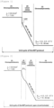
- Figure 1 is a graph showing one embodiment of the accelerated evaluation method for an anode of the present invention.
- the J e step of loading an oxidation current of 0.6 A/cm 2 for water electrolysis to an anode is performed for a duration of T e in an alkali aqueous solution at room temperature to 100°C during the evaluation cycles, and then the E min step of holding the anode at a constant potential lower than the open circuit potential is performed for a duration of T min . Then, each of these J e step and E min step is repeated 100 times or more.
- Each of the duration T e and the duration T min is preferably set to 120 s (2 min) or shorter, more preferably 90 s or shorter, particularly preferably 60 s or shorter, and most preferably 45 s or shorter.
- the time required for the evaluation is excessively long, and even if each of the duration T e and the duration T min is made longer than 120 s, an increase in the degradation rate of an anode is not expected.
- an anode is preferably held at a potential 0.6 to 1.0 V lower than the open circuit potential. When an anode is held at a potential higher than this range, the degradation rate is likely to decrease.
- excessive reduction of a catalyst may be induced or hydrogen may be evolved. Therefore, the degradation behavior may be somewhat different from the degradation behavior in actual operation in some cases.
- the accelerated evaluation method for an anode of the present invention preferably further includes an LSV step of performing, between the J e step and the E min step, linear sweep voltammetry (LSV) that starts from a potential lower than a potential at the time when the J e step is completed.
- LSV linear sweep voltammetry
- the LSV is usually started from a potential (“1.5 V" in Figure 1 ) near the open circuit potential.
- the range of the scan rate SR in the LSV is preferably set to 50 to 500 mV/s.
- FIG. 2 is a graph showing another embodiment of the accelerated evaluation method for an anode of the present invention.
- the accelerated evaluation method for an anode of the present invention preferably further includes an OCP step of holding the anode at the open circuit potential between the J e step and the LSV step.
- the actual fluctuation states of electric power having a large output fluctuation, such as renewable energy can be simulated more suitably.
- the holding time for holding the anode at the open circuit potential is preferably set to 10 to 60 s. When the holding time is excessively short, it may be difficult to obtain the effect of retaining the anode at the open circuit potential in some cases. On the other hand, when the holding time is excessively long, the significance of providing the OCP step may be lost in some cases.
- the number of repetition (number of cycles) of each of the J e step and the E min step depends on the type of the anode to be an object of the evaluation, or the like, and is 100 or more, preferably 10,000 or less. Further, the time required for each step is preferably set such that the overall time required for the evaluation is about several hours to about several hundred hours.
- the alkaline water electrolysis anode (hereinafter, also simply referred to as "anode") is provided with, for example, an electrically conductive substrate, an intermediate layer arbitrarily formed on the surface of the electrically conductive substrate, and a catalyst layer formed on the surface of the intermediate layer.
- the electrically conductive substrate is an electric conductor that conducts electricity for electrolysis and is an element having a function as a carrier that carries the intermediate layer and the catalyst layer.
- At least a surface of the electrically conductive substrate (the surface on which the intermediate layer and the catalyst layer are formed) is formed with nickel or a nickel base alloy. That is, the whole of the electrically conductive substrate may be formed with nickel or a nickel base alloy, or only the surface of the electrically conductive substrate may be formed with nickel or a nickel base alloy.
- the electrically conductive substrate may be such that a coating of nickel or a nickel base alloy is formed on the surface of a metal material, such as iron, stainless steel, aluminum, or titanium, by plating or the like.
- the thickness of the electrically conductive substrate is preferably 0.05 to 5 mm.
- the shape of the electrically conductive substrate is preferably a shape having an opening for removing bubbles of oxygen, hydrogen, and the like to be produced.
- an expanded mesh or a porous expanded mesh can be used as the electrically conductive substrate.
- the aperture ratio of the electrically conductive substrate is preferably 10 to 95%.
- the catalyst layer is a layer that is formed on the surface of the electrically conductive substrate or the surface of the intermediate layer and has catalytic ability. By interposing the intermediate layer, the catalyst layer is more firmly fixed on the electrically conductive substrate.
- the type of the catalyst contained in the catalyst layer is not particularly limited, and a catalyst having catalytic ability according to the purpose can be selected for use.
- Specific examples of the catalyst include nickel cobalt spinel oxide (NiCo 2 O 4 ), a lanthanoid nickel cobalt perovskite oxide, an iridium oxide, a ruthenium oxide, and a lithium nickel cobalt perovskite oxide.
- the lanthanoid nickel cobalt perovskite oxide is represented by structural formula: XNi a Co 1-a O 3 wherein X represents at least any one of metals of lanthanum, cerium, and praseodymium, and 0 ⁇ a ⁇ 1.
- the catalyst layer may be formed with a single catalyst or may be formed with a plurality of catalysts. When a plurality of catalysts is used, a catalyst layer of a single layer can be formed by mixing a plurality of the catalysts.
- a catalyst layer of a stacked type may be prepared by stacking a plurality of catalyst layers. When the catalyst layer of a stacked type is prepared, each layer may be formed with a single catalyst, or each layer may be formed with a plurality of catalysts. For example, after a first layer composed of a lithium nickel oxide or nickel cobalt spinel oxide is formed on the intermediate layer, a second layer composed of an iridium oxide may be stacked on the first layer.
- the thickness, density, and the like of the catalyst layer are not particularly limited and may appropriately be set according to the use application of the anode, or the like.
- the anode can be produced by forming an intermediate layer as necessary on the surface of the electrically conductive substrate and then forming a catalyst layer.
- the catalyst layer can be formed by, for example, a thermal decomposition method, electroplating, sputtering, ion plating, plasma spraying, or the like.
- the method for producing an anode will be described taking for example a method for forming a catalyst layer by a thermal decomposition method.
- the electrically conductive substrate is preferably subjected to a chemical etching treatment in advance for the purpose of removing contamination particles of a metal, an organic substance, and the like on the surface before forming the catalyst layer.
- the consumption of the electrically conductive substrate by the chemical etching treatment is preferably set to about 30 g/m 2 or more and about 400 g/m 2 or less.
- the surface of the electrically conductive substrate is preferably subjected to a roughening treatment in advance for the purpose of enhancing the adhesiveness with the intermediate layer and the catalyst layer. Examples of the means for the roughening treatment include a blast treatment in which a powder is sprayed, an etching treatment using an acid that can dissolve the substrate, and plasma spraying.
- aqueous solution of a precursor containing a desired metal ion is coated on the surface of the electrically conductive substrate on which a chemical etching treatment has been performed.
- the coating method include brash coating, roller coating, spin coating, and electrostatic coating.
- the electrically conductive substrate coated with the aqueous solution is dried as necessary.
- the drying temperature is preferably set to a temperature to avoid rapid evaporation of the solvent (for example, about 60 to about 80°C).
- the electrically conductive substrate whose surface has been coated with the aqueous solution of the precursor is subjected to a thermal treatment.
- the catalyst layer can be formed on the surface of the electrically conductive substrate.
- the thermal treatment temperature can appropriately be set.
- the thermal treatment temperature is preferably set to 450 to 600°C, more preferably 450 to 550°C.
- the decomposition temperature of lithium nitrate is about 430°C
- the decomposition temperature of nickel acetate is about 373°C.
- the thermal treatment temperature is set to 450°C or higher, thereby each component can more surely be decomposed.
- the thermal treatment time may appropriately be set taking the reaction rate, the productivity, the oxidation resistance at the surface of the catalyst layer, and the like into consideration.
- the thickness of the catalyst layer to be formed can be controlled.
- the coating and drying of the aqueous solution may be repeated for every layer until the uppermost layer is formed, and thereafter the thermal treatment may be performed on the whole layers, or the coating of the aqueous solution and the thermal treatment (pre-treatment) may be repeated for every layer until the uppermost layer is formed, and thereafter the thermal treatment may be performed on the whole layers.
- the temperature of the pre-treatment and the temperature of the thermal treatment on the whole layers may be the same or different.
- the time for the pre-treatment is preferably made shorter than the time for the thermal treatment on the whole layers.
- electrochemical cells volume: 5 L
- PTFE polytetrafluoroethylene
- Each of these electrochemical cells is a three-electrode cell using an object to be evaluated (anode) as a working electrode, RHE as a reference electrode, and spiral nickel wire as a counter electrode.
- the working electrode had a surface area of 1.0 cm 2 and was connected to Ni wire shielded with a heat-shrinkable tube. The distance between the Luggin capillaries of the working electrode and the reference electrode was fixed within about 1 cm.
- the counter electrode was installed in a cylindrical neutral separator in order to prevent diffusion of hydrogen to be mainly produced into the electrolyte in the cell.
- a 7.0 mol/L KOH aqueous solution was used as the electrolyte.
- the temperature of the electrolyte was retained at 80°C and 25°C during the pre-treatment (electrochemical activation) and the accelerated evaluation, respectively.
- a Bio-Logic SAS potentiostat (model: VSP-300) controlled by dedicated software (EC-Lab V11.30) was used for the electrochemical operation.
- As the electrochemical pre-treatment water electrolysis was performed using the anode to be an object of the evaluation at a constant current of 1.0 A/cm 2 at 80°C for 2 hours.
- the obtained coating solution was coated on the surface of a surface-treated nickel substrate in such a way that the amount of the metals per coating was 1 g/m 2 , and then dried at room temperature for 10 minutes and at 60°C for 10 minutes. Subsequently, a thermal treatment was performed at 350°C for 15 minutes in an air-circulating electric furnace for thermal decomposition.
- the amount of the metals in the formed catalyst layer was 4 g/m 2 .
- an LSV step of holding the potential at the time when the J e step was completed at 1.5 V vs. RHE, and performing the LSV at a scan rate SR of 500 mV/s from the potential was provided between the J e step and the E min step in order to simulate the actual fluctuation of electric power, such as renewable energy.
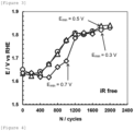
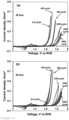
- Figure 3 shows a graph obtained by plotting electrode potentials at an oxidation current of 0.1 A/cm 2 versus the number of cycles. The values of the electrode potentials in Figure 3 were calculated from the polarization curves (sweep rate: 5 mV/s) shown in Figure 4 .
- FIG. 1 the evaluation was performed fixing the holding potential (E min ) in the E min step to 0.5 V and changing only the duration T min .
- Figure 6 shows a graph obtained by plotting electrode potentials at an oxidation current o 0.1 A/cm 2 versus the number of cycles. The values of the electrode potentials in Figure 6 were calculated from the polarization curves (sweep rate: 5 mV/s) shown in Figure 7 .
- FIG. 1 the evaluation was performed fixing the holding potential (E min ) in the E min step to 0.5 V and the duration T min to 60 s and changing only the scan rate SR in the LSV step.
- Figures 9 and 10 each show a graph obtained by plotting electrode potentials at an oxidation current o 0.1 A/cm 2 versus the number of cycles.
- the scan rates SRs of 50 mV/s and 500 mV/s, the electrode exhibited more favorable durability when the scan rate was 500 mV/s.
- Figure 10 shows that when the scan rate SR was 50 mV/s, region B appeared from a smaller number of cycles. As described above, it is clear that by decreasing the scan rate SR, the degradation reaction on the surface of the anode is accelerated.
- the evaluation was performed further providing the OCP step of holding the anode at the open circuit potential between the J e step and the LSV step. Note that the evaluation was performed fixing the holding potential in the E min step to 0.5 V and the duration T min to 60 s and changing only the holding time in the OCP step in a range of 10 to 60 s.
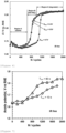
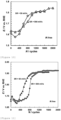
- Figure 11 shows a graph obtained by plotting electrode potentials at an oxidation current of 0.1 A/cm 2 versus the number of cycles. The values of the electrode potentials in Figure 11 were calculated from the polarization curves (sweep rate: 5 mV/s) shown in Figure 12 .
- Figure 11 shows that the interval in the OCP step gives a significant influence on an improvement in the durability of the anode.
- Figure 13 shows that the range where the anode exhibits stable catalytic activity (region A) was clearly extended and the rate of progress in the subsequent region (region B) was remarkably lowered due to the presence of the OCP step.
- a phenomenon that the durability of the electrode catalyst is significantly improved by providing the OCP step was found. The reason is not necessarily clear, but it is inferred that by holding the anode at the open circuit potential, the structural change of the catalyst layer that had occurred in the J e step was relaxed and recovered and the progress of the degradation in the E min step that followed was suppressed. This phenomenon may occur in an actual machine, and therefore an accelerated evaluation method for durability that corresponds better to an actual machine can be established by providing the OCP step.
- the accelerated evaluation method for an anode of the present invention is useful as a method for evaluating, in an accelerated manner, an alkaline water electrolysis anode, such as, for example, an oxygen evolution electrode using electric power having a large output fluctuation, such as renewable energy, as a power source.
Landscapes
- Chemical & Material Sciences (AREA)
- Chemical Kinetics & Catalysis (AREA)
- Electrochemistry (AREA)
- Life Sciences & Earth Sciences (AREA)
- Health & Medical Sciences (AREA)
- Engineering & Computer Science (AREA)
- Materials Engineering (AREA)
- Metallurgy (AREA)
- Organic Chemistry (AREA)
- Molecular Biology (AREA)
- Physics & Mathematics (AREA)
- Analytical Chemistry (AREA)
- Biochemistry (AREA)
- General Health & Medical Sciences (AREA)
- General Physics & Mathematics (AREA)
- Immunology (AREA)
- Pathology (AREA)
- Inorganic Chemistry (AREA)
- Electrolytic Production Of Non-Metals, Compounds, Apparatuses Therefor (AREA)
- Testing Resistance To Weather, Investigating Materials By Mechanical Methods (AREA)
Applications Claiming Priority (2)
| Application Number | Priority Date | Filing Date | Title |
|---|---|---|---|
| JP2020193246A JP7576260B2 (ja) | 2020-11-20 | 2020-11-20 | アノードの加速評価方法 |
| PCT/JP2021/042309 WO2022107828A1 (fr) | 2020-11-20 | 2021-11-17 | Procédé d'évaluation accélérée d'anode |
Publications (2)
| Publication Number | Publication Date |
|---|---|
| EP4249637A1 true EP4249637A1 (fr) | 2023-09-27 |
| EP4249637A4 EP4249637A4 (fr) | 2025-06-18 |
Family
ID=81708045
Family Applications (1)
| Application Number | Title | Priority Date | Filing Date |
|---|---|---|---|
| EP21894701.8A Pending EP4249637A4 (fr) | 2020-11-20 | 2021-11-17 | Procédé d'évaluation accélérée d'anode |
Country Status (6)
| Country | Link |
|---|---|
| US (1) | US12467901B2 (fr) |
| EP (1) | EP4249637A4 (fr) |
| JP (1) | JP7576260B2 (fr) |
| KR (1) | KR102946184B1 (fr) |
| CN (1) | CN116472366B (fr) |
| WO (1) | WO2022107828A1 (fr) |
Families Citing this family (3)
| Publication number | Priority date | Publication date | Assignee | Title |
|---|---|---|---|---|
| JPWO2023042590A1 (fr) * | 2021-09-16 | 2023-03-23 | ||
| CN115184207B (zh) * | 2022-07-14 | 2025-12-05 | 苏州大学 | 工业条件下电解水催化电极的稳定性评估方法 |
| EP4600408A1 (fr) * | 2022-11-10 | 2025-08-13 | De Nora Permelec Ltd | Électrode positive pour électrolyse et son procédé de production |
Family Cites Families (12)
| Publication number | Priority date | Publication date | Assignee | Title |
|---|---|---|---|---|
| US2928783A (en) | 1956-08-23 | 1960-03-15 | Era Patents Ltd | Porous nickel electrode |
| GB864457A (en) | 1956-08-23 | 1961-04-06 | Era Patents Ltd | Improvements relating to hydrogen-oxygen cells particularly for use as electrolysers |
| US4498962A (en) | 1982-07-10 | 1985-02-12 | Agency Of Industrial Science And Technology | Anode for the electrolysis of water |
| US6572758B2 (en) * | 2001-02-06 | 2003-06-03 | United States Filter Corporation | Electrode coating and method of use and preparation thereof |
| KR100864457B1 (ko) | 2007-10-12 | 2008-10-20 | 주식회사 우전그린 | 노면표시 도로 구조물 |
| JP2010186704A (ja) * | 2009-02-13 | 2010-08-26 | Hitachi Maxell Ltd | 固体高分子型燃料電池の寿命加速試験方法 |
| JP2015086420A (ja) | 2013-10-29 | 2015-05-07 | 国立大学法人横浜国立大学 | アルカリ水電解用陽極 |
| KR101733492B1 (ko) | 2015-01-09 | 2017-05-11 | 한국과학기술연구원 | 음극 및 양극에서 각각 수소와 산소를 발생시키는 비귀금속계 수전해 촉매 및 이의 제조방법 |
| JP6615682B2 (ja) | 2016-04-12 | 2019-12-04 | デノラ・ペルメレック株式会社 | アルカリ水電解用陽極及びアルカリ水電解用陽極の製造方法 |
| JP7092076B2 (ja) | 2018-03-12 | 2022-06-28 | 三菱マテリアル株式会社 | チタン基材、チタン基材の製造方法、及び、水電解用電極、水電解装置 |
| CN111458398A (zh) * | 2020-03-25 | 2020-07-28 | 先进储能材料国家工程研究中心有限责任公司 | 燃料电池用催化剂材料加速评价方法 |
| KR102928783B1 (ko) | 2022-06-29 | 2026-02-23 | 주식회사 이앤에스디자인 | 승강기의 실제 운행 빅데이터 서비스 제공 시스템 및 방법 |
-
2020
- 2020-11-20 JP JP2020193246A patent/JP7576260B2/ja active Active
-
2021
- 2021-11-17 US US18/253,458 patent/US12467901B2/en active Active
- 2021-11-17 EP EP21894701.8A patent/EP4249637A4/fr active Pending
- 2021-11-17 KR KR1020237019023A patent/KR102946184B1/ko active Active
- 2021-11-17 CN CN202180077967.8A patent/CN116472366B/zh active Active
- 2021-11-17 WO PCT/JP2021/042309 patent/WO2022107828A1/fr not_active Ceased
Also Published As
| Publication number | Publication date |
|---|---|
| US20230408444A1 (en) | 2023-12-21 |
| CN116472366B (zh) | 2025-10-28 |
| KR102946184B1 (ko) | 2026-03-30 |
| US12467901B2 (en) | 2025-11-11 |
| JP2022081975A (ja) | 2022-06-01 |
| CA3197436A1 (fr) | 2022-05-27 |
| EP4249637A4 (fr) | 2025-06-18 |
| JP7576260B2 (ja) | 2024-10-31 |
| CN116472366A (zh) | 2023-07-21 |
| KR20230101884A (ko) | 2023-07-06 |
| WO2022107828A1 (fr) | 2022-05-27 |
Similar Documents
| Publication | Publication Date | Title |
|---|---|---|
| EP3763849B1 (fr) | Électrode d'électrolyse et son procédé de fabrication | |
| US11692276B2 (en) | Alkaline water electrolysis method, and anode for alkaline water electrolysis | |
| EP3064614B1 (fr) | Anode pour l'électrolyse d'une eau alcaline | |
| US12467901B2 (en) | Accelerated evaluation method for anode | |
| EP3511443B1 (fr) | Procede de fabrication d'une anode pour l'électrolyse d'eau alcaline et anode pour l'électrolyse d'eau alcaline | |
| EP3940117B1 (fr) | Procédé d'électrolyse d'eau alcaline et anode pour électrolyse d'eau alcaline | |
| Sayed et al. | Activation/deactivation behavior of nano-NiOx based anodes towards the OER: Influence of temperature | |
| EP4190944B1 (fr) | Anode pour électrolyse d'eau alcaline et son procédé de production | |
| EP2730681A1 (fr) | Electrode pour électrolyse, son procédé de fabrication et appareil d'électrolyse | |
| CA3197436C (fr) | Procede d'evaluation acceleree d'anode | |
| EP4600408A1 (fr) | Électrode positive pour électrolyse et son procédé de production | |
| KR102841177B1 (ko) | 수전해 촉매 활성 촉진제 및 이를 이용한 수전해 장치 | |
| KR20240113932A (ko) | 전해용 전극 및 그 제조 방법 | |
| HALEEM et al. | The Electrochemical Society of Japan |
Legal Events
| Date | Code | Title | Description |
|---|---|---|---|
| STAA | Information on the status of an ep patent application or granted ep patent |
Free format text: STATUS: THE INTERNATIONAL PUBLICATION HAS BEEN MADE |
|
| PUAI | Public reference made under article 153(3) epc to a published international application that has entered the european phase |
Free format text: ORIGINAL CODE: 0009012 |
|
| STAA | Information on the status of an ep patent application or granted ep patent |
Free format text: STATUS: REQUEST FOR EXAMINATION WAS MADE |
|
| 17P | Request for examination filed |
Effective date: 20230606 |
|
| AK | Designated contracting states |
Kind code of ref document: A1 Designated state(s): AL AT BE BG CH CY CZ DE DK EE ES FI FR GB GR HR HU IE IS IT LI LT LU LV MC MK MT NL NO PL PT RO RS SE SI SK SM TR |
|
| DAV | Request for validation of the european patent (deleted) | ||
| DAX | Request for extension of the european patent (deleted) | ||
| A4 | Supplementary search report drawn up and despatched |
Effective date: 20250515 |
|
| RIC1 | Information provided on ipc code assigned before grant |
Ipc: G01N 27/48 20060101ALI20250509BHEP Ipc: C25B 15/00 20060101ALI20250509BHEP Ipc: C25B 11/00 20210101ALI20250509BHEP Ipc: C25B 1/04 20210101AFI20250509BHEP |