EP3763849B1 - Électrode d'électrolyse et son procédé de fabrication - Google Patents
Électrode d'électrolyse et son procédé de fabrication Download PDFInfo
- Publication number
- EP3763849B1 EP3763849B1 EP19763900.8A EP19763900A EP3763849B1 EP 3763849 B1 EP3763849 B1 EP 3763849B1 EP 19763900 A EP19763900 A EP 19763900A EP 3763849 B1 EP3763849 B1 EP 3763849B1
- Authority
- EP
- European Patent Office
- Prior art keywords
- nickel
- electrolysis
- intermediate layer
- electrode
- lithium
- Prior art date
- Legal status (The legal status is an assumption and is not a legal conclusion. Google has not performed a legal analysis and makes no representation as to the accuracy of the status listed.)
- Active
Links
Images


Classifications
-
- C—CHEMISTRY; METALLURGY
- C25—ELECTROLYTIC OR ELECTROPHORETIC PROCESSES; APPARATUS THEREFOR
- C25B—ELECTROLYTIC OR ELECTROPHORETIC PROCESSES FOR THE PRODUCTION OF COMPOUNDS OR NON-METALS; APPARATUS THEREFOR
- C25B11/00—Electrodes; Manufacture thereof not otherwise provided for
- C25B11/04—Electrodes; Manufacture thereof not otherwise provided for characterised by the material
- C25B11/051—Electrodes formed of electrocatalysts on a substrate or carrier
- C25B11/052—Electrodes comprising one or more electrocatalytic coatings on a substrate
-
- C—CHEMISTRY; METALLURGY
- C25—ELECTROLYTIC OR ELECTROPHORETIC PROCESSES; APPARATUS THEREFOR
- C25B—ELECTROLYTIC OR ELECTROPHORETIC PROCESSES FOR THE PRODUCTION OF COMPOUNDS OR NON-METALS; APPARATUS THEREFOR
- C25B11/00—Electrodes; Manufacture thereof not otherwise provided for
- C25B11/04—Electrodes; Manufacture thereof not otherwise provided for characterised by the material
- C25B11/051—Electrodes formed of electrocatalysts on a substrate or carrier
- C25B11/073—Electrodes formed of electrocatalysts on a substrate or carrier characterised by the electrocatalyst material
- C25B11/075—Electrodes formed of electrocatalysts on a substrate or carrier characterised by the electrocatalyst material consisting of a single catalytic element or catalytic compound
- C25B11/077—Electrodes formed of electrocatalysts on a substrate or carrier characterised by the electrocatalyst material consisting of a single catalytic element or catalytic compound the compound being a non-noble metal oxide
- C25B11/0771—Electrodes formed of electrocatalysts on a substrate or carrier characterised by the electrocatalyst material consisting of a single catalytic element or catalytic compound the compound being a non-noble metal oxide of the spinel type
-
- C—CHEMISTRY; METALLURGY
- C23—COATING METALLIC MATERIAL; COATING MATERIAL WITH METALLIC MATERIAL; CHEMICAL SURFACE TREATMENT; DIFFUSION TREATMENT OF METALLIC MATERIAL; COATING BY VACUUM EVAPORATION, BY SPUTTERING, BY ION IMPLANTATION OR BY CHEMICAL VAPOUR DEPOSITION, IN GENERAL; INHIBITING CORROSION OF METALLIC MATERIAL OR INCRUSTATION IN GENERAL
- C23C—COATING METALLIC MATERIAL; COATING MATERIAL WITH METALLIC MATERIAL; SURFACE TREATMENT OF METALLIC MATERIAL BY DIFFUSION INTO THE SURFACE, BY CHEMICAL CONVERSION OR SUBSTITUTION; COATING BY VACUUM EVAPORATION, BY SPUTTERING, BY ION IMPLANTATION OR BY CHEMICAL VAPOUR DEPOSITION, IN GENERAL
- C23C18/00—Chemical coating by decomposition of either liquid compounds or solutions of the coating forming compounds, without leaving reaction products of surface material in the coating; Contact plating
- C23C18/02—Chemical coating by decomposition of either liquid compounds or solutions of the coating forming compounds, without leaving reaction products of surface material in the coating; Contact plating by thermal decomposition
- C23C18/12—Chemical coating by decomposition of either liquid compounds or solutions of the coating forming compounds, without leaving reaction products of surface material in the coating; Contact plating by thermal decomposition characterised by the deposition of inorganic material other than metallic material
- C23C18/1204—Chemical coating by decomposition of either liquid compounds or solutions of the coating forming compounds, without leaving reaction products of surface material in the coating; Contact plating by thermal decomposition characterised by the deposition of inorganic material other than metallic material inorganic material, e.g. non-oxide and non-metallic such as sulfides, nitrides based compounds
- C23C18/1208—Oxides, e.g. ceramics
- C23C18/1216—Metal oxides
-
- C—CHEMISTRY; METALLURGY
- C25—ELECTROLYTIC OR ELECTROPHORETIC PROCESSES; APPARATUS THEREFOR
- C25B—ELECTROLYTIC OR ELECTROPHORETIC PROCESSES FOR THE PRODUCTION OF COMPOUNDS OR NON-METALS; APPARATUS THEREFOR
- C25B1/00—Electrolytic production of inorganic compounds or non-metals
- C25B1/01—Products
- C25B1/02—Hydrogen or oxygen
- C25B1/04—Hydrogen or oxygen by electrolysis of water
-
- C—CHEMISTRY; METALLURGY
- C25—ELECTROLYTIC OR ELECTROPHORETIC PROCESSES; APPARATUS THEREFOR
- C25B—ELECTROLYTIC OR ELECTROPHORETIC PROCESSES FOR THE PRODUCTION OF COMPOUNDS OR NON-METALS; APPARATUS THEREFOR
- C25B11/00—Electrodes; Manufacture thereof not otherwise provided for
- C25B11/04—Electrodes; Manufacture thereof not otherwise provided for characterised by the material
- C25B11/051—Electrodes formed of electrocatalysts on a substrate or carrier
- C25B11/055—Electrodes formed of electrocatalysts on a substrate or carrier characterised by the substrate or carrier material
- C25B11/069—Electrodes formed of electrocatalysts on a substrate or carrier characterised by the substrate or carrier material consisting of at least one single element and at least one compound; consisting of two or more compounds
-
- C—CHEMISTRY; METALLURGY
- C25—ELECTROLYTIC OR ELECTROPHORETIC PROCESSES; APPARATUS THEREFOR
- C25B—ELECTROLYTIC OR ELECTROPHORETIC PROCESSES FOR THE PRODUCTION OF COMPOUNDS OR NON-METALS; APPARATUS THEREFOR
- C25B11/00—Electrodes; Manufacture thereof not otherwise provided for
- C25B11/04—Electrodes; Manufacture thereof not otherwise provided for characterised by the material
- C25B11/051—Electrodes formed of electrocatalysts on a substrate or carrier
- C25B11/073—Electrodes formed of electrocatalysts on a substrate or carrier characterised by the electrocatalyst material
- C25B11/075—Electrodes formed of electrocatalysts on a substrate or carrier characterised by the electrocatalyst material consisting of a single catalytic element or catalytic compound
-
- C—CHEMISTRY; METALLURGY
- C25—ELECTROLYTIC OR ELECTROPHORETIC PROCESSES; APPARATUS THEREFOR
- C25B—ELECTROLYTIC OR ELECTROPHORETIC PROCESSES FOR THE PRODUCTION OF COMPOUNDS OR NON-METALS; APPARATUS THEREFOR
- C25B11/00—Electrodes; Manufacture thereof not otherwise provided for
- C25B11/04—Electrodes; Manufacture thereof not otherwise provided for characterised by the material
- C25B11/051—Electrodes formed of electrocatalysts on a substrate or carrier
- C25B11/073—Electrodes formed of electrocatalysts on a substrate or carrier characterised by the electrocatalyst material
- C25B11/075—Electrodes formed of electrocatalysts on a substrate or carrier characterised by the electrocatalyst material consisting of a single catalytic element or catalytic compound
- C25B11/077—Electrodes formed of electrocatalysts on a substrate or carrier characterised by the electrocatalyst material consisting of a single catalytic element or catalytic compound the compound being a non-noble metal oxide
-
- C—CHEMISTRY; METALLURGY
- C25—ELECTROLYTIC OR ELECTROPHORETIC PROCESSES; APPARATUS THEREFOR
- C25B—ELECTROLYTIC OR ELECTROPHORETIC PROCESSES FOR THE PRODUCTION OF COMPOUNDS OR NON-METALS; APPARATUS THEREFOR
- C25B11/00—Electrodes; Manufacture thereof not otherwise provided for
- C25B11/04—Electrodes; Manufacture thereof not otherwise provided for characterised by the material
- C25B11/051—Electrodes formed of electrocatalysts on a substrate or carrier
- C25B11/073—Electrodes formed of electrocatalysts on a substrate or carrier characterised by the electrocatalyst material
- C25B11/075—Electrodes formed of electrocatalysts on a substrate or carrier characterised by the electrocatalyst material consisting of a single catalytic element or catalytic compound
- C25B11/077—Electrodes formed of electrocatalysts on a substrate or carrier characterised by the electrocatalyst material consisting of a single catalytic element or catalytic compound the compound being a non-noble metal oxide
- C25B11/0773—Electrodes formed of electrocatalysts on a substrate or carrier characterised by the electrocatalyst material consisting of a single catalytic element or catalytic compound the compound being a non-noble metal oxide of the perovskite type
-
- C—CHEMISTRY; METALLURGY
- C25—ELECTROLYTIC OR ELECTROPHORETIC PROCESSES; APPARATUS THEREFOR
- C25B—ELECTROLYTIC OR ELECTROPHORETIC PROCESSES FOR THE PRODUCTION OF COMPOUNDS OR NON-METALS; APPARATUS THEREFOR
- C25B11/00—Electrodes; Manufacture thereof not otherwise provided for
- C25B11/04—Electrodes; Manufacture thereof not otherwise provided for characterised by the material
- C25B11/051—Electrodes formed of electrocatalysts on a substrate or carrier
- C25B11/073—Electrodes formed of electrocatalysts on a substrate or carrier characterised by the electrocatalyst material
- C25B11/091—Electrodes formed of electrocatalysts on a substrate or carrier characterised by the electrocatalyst material consisting of at least one catalytic element and at least one catalytic compound; consisting of two or more catalytic elements or catalytic compounds
- C25B11/093—Electrodes formed of electrocatalysts on a substrate or carrier characterised by the electrocatalyst material consisting of at least one catalytic element and at least one catalytic compound; consisting of two or more catalytic elements or catalytic compounds at least one noble metal or noble metal oxide and at least one non-noble metal oxide
-
- Y—GENERAL TAGGING OF NEW TECHNOLOGICAL DEVELOPMENTS; GENERAL TAGGING OF CROSS-SECTIONAL TECHNOLOGIES SPANNING OVER SEVERAL SECTIONS OF THE IPC; TECHNICAL SUBJECTS COVERED BY FORMER USPC CROSS-REFERENCE ART COLLECTIONS [XRACs] AND DIGESTS
- Y02—TECHNOLOGIES OR APPLICATIONS FOR MITIGATION OR ADAPTATION AGAINST CLIMATE CHANGE
- Y02E—REDUCTION OF GREENHOUSE GAS [GHG] EMISSIONS, RELATED TO ENERGY GENERATION, TRANSMISSION OR DISTRIBUTION
- Y02E60/00—Enabling technologies; Technologies with a potential or indirect contribution to GHG emissions mitigation
- Y02E60/30—Hydrogen technology
- Y02E60/36—Hydrogen production from non-carbon containing sources, e.g. by water electrolysis
-
- Y—GENERAL TAGGING OF NEW TECHNOLOGICAL DEVELOPMENTS; GENERAL TAGGING OF CROSS-SECTIONAL TECHNOLOGIES SPANNING OVER SEVERAL SECTIONS OF THE IPC; TECHNICAL SUBJECTS COVERED BY FORMER USPC CROSS-REFERENCE ART COLLECTIONS [XRACs] AND DIGESTS
- Y02—TECHNOLOGIES OR APPLICATIONS FOR MITIGATION OR ADAPTATION AGAINST CLIMATE CHANGE
- Y02P—CLIMATE CHANGE MITIGATION TECHNOLOGIES IN THE PRODUCTION OR PROCESSING OF GOODS
- Y02P20/00—Technologies relating to chemical industry
- Y02P20/10—Process efficiency
- Y02P20/133—Renewable energy sources, e.g. sunlight
Definitions
- the present invention relates to an electrode for electrolysis and a method for producing the same.
- Hydrogen is secondary energy that is suitable for storage and transportation and gives small environmental load, and therefore a hydrogen energy system using hydrogen as an energy carrier has been attracting attention.
- hydrogen is mainly produced by: steam reforming of fossil fuels; and other methods, but the importance of alkaline water electrolysis using renewable energy as a power source has been increasing from the viewpoint of global warming and a problem of exhaustion of fossil fuels.
- Water electrolysis is roughly classified into two.
- the one is alkaline water electrolysis, in which a high-concentration alkali aqueous solution is used as an electrolyte.
- the other is solid polymer type water electrolysis, in which a solid polymer electrolyte membrane (SPE) is used as an electrolyte.
- SPE solid polymer electrolyte membrane
- Electrolysis performance has been improved up to about 1.7 to about 1.9 V (78 to 87% in terms of efficiency) in a current density of 0.3 to 0.4 Acm -2 due to development of constituent materials and various piping materials for an electrolytic bath, which are resistant to a high-temperature, high-concentration alkali aqueous solution, and development of a low-resistance separator and an electrode having an enlarged surface area and containing a catalyst added therein.
- Non Patent Literatures 1 and 2 A nickel-based material which is stable in a high-concentration alkali aqueous solution has been used as an anode for alkaline water electrolysis, and it is reported that a nickel-based anode has a life of several decades or longer in the case of alkaline water electrolysis using a stable power source (Non Patent Literatures 1 and 2).
- Non Patent Literature 3 when renewable energy is used as a power source, severe conditions, such as extremely frequent starts/stops and load fluctuation, are brought about in many cases, so that deterioration in the performance of the nickel-based anode has been regarded as a problem.
- An electric current generated by the battery reaction leaks through piping which connects cells in the case of an electrolytic bath in which a plurality of cells is combined.
- Examples of the countermeasure for preventing such a leak of the electric current include a method of allowing a weak electric current to flow continuously during a stop.
- allowing a weak electric current to flow continuously during a stop needs special power supply control and leads to generation of oxygen and hydrogen at all times, and therefore has a problem of taking excessive labor for operation management.
- a platinum group metal, a platinum group metal oxide, a valve metal oxide, an iron group oxide, a lanthanide group metal oxide, or the like has been utilized as a catalyst (anode catalyst) for an oxygen-generating anode which is used for alkaline water electrolysis.
- alloy-based catalysts such as Ni-Co and Ni-Fe, in which nickel is used as a base; nickel having an enlarged surface area; electrically conductive oxides (ceramic materials), such as spinel-based Co 3 O 4 and NiCo 2 O 4 , and perovskite-based LaCoO 3 and LaNiO 3 ; noble metal oxides; oxides containing a lanthanide group metal and a noble metal; and the like are also known (Non Patent Literature 4).
- an anode having a lithium-containing nickel oxide layer formed in advance on a surface of a nickel substrate As an oxygen-generating anode which is used for high-concentration alkaline water electrolysis, an anode having a lithium-containing nickel oxide layer formed in advance on a surface of a nickel substrate is known (Patent Literatures 1 and 2).
- Patent Literatures 1 and 2 an anode for alkaline water electrolysis having a lithium-containing nickel oxide catalyst layer containing lithium and nickel in a predetermined molar ratio, the lithium-containing nickel oxide catalyst layer formed on a surface of a nickel substrate, (Patent Literature 3), and an anode for alkaline water electrolysis having a catalyst layer containing a nickel cobalt-based oxide, and an iridium oxide or a ruthenium oxide, the catalyst layer formed on a surface of a nickel substrate, (Patent Literature 4) are proposed.
- the present invention has been completed in view of such problems of the conventional techniques, and an object of the present invention is to provide an electrode for electrolysis in which electrolysis performance is hard to deteriorate and excellent catalytic activity is kept stable over a long period of time even when electric power in which there is a large fluctuation in output, such as renewable energy, is used as a power source.
- another object of the present invention is to provide a method for producing the electrode for electrolysis.
- the present inventors have conducted diligent studies in order to solve the problems to find out that the problems can be solved by disposing a catalyst layer on a surface of an electrically conductive substrate through an intermediate layer containing a lithium-containing nickel oxide represented by predetermined composition formula, and have completed the present invention.
- the present invention relates to the subject matter of claims 1 to 4. That is, according to the present invention, an electrode for electrolysis described below is provided.
- an electrode for electrolysis in which electrolysis performance is hard to deteriorate and excellent catalytic activity is kept stable over a long period of time even when electric power in which there is a large fluctuation in output, such as renewable energy, is used as a power source can be provided.
- a method for producing the electrode for electrolysis can be provided.
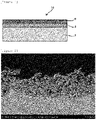
- FIG. 1 is a sectional view schematically illustrating one embodiment of an electrode for electrolysis of the present invention.
- an electrode 10 for electrolysis of the present embodiment is provided with: an electrically conductive substrate 2; an intermediate layer 4 formed on the surface of the electrically conductive substrate 2; and a catalyst layer 6 formed on the surface of the intermediate layer 4.
- an electrically conductive substrate 2 As illustrated in Figure 1 , an electrode 10 for electrolysis of the present embodiment is provided with: an electrically conductive substrate 2; an intermediate layer 4 formed on the surface of the electrically conductive substrate 2; and a catalyst layer 6 formed on the surface of the intermediate layer 4.
- the electrically conductive substrate 2 is an electric conductor for conducting electricity for electrolysis and is a member having a function as a carrier for carrying the intermediate layer 4 and the catalyst layer 6. At least the surface of the electrically conductive substrate 2 (the face where the intermediate layer 4 is to be formed) is formed with nickel or a nickel-based alloy. That is, the whole of the electrically conductive substrate 2 may be formed with nickel or a nickel-based alloy, or only the surface thereof may be formed with nickel or a nickel-based alloy. Specifically, the electrically conductive substrate 2 may be such that a coating of nickel or a nickel-based alloy is formed by plating or the like on the surface of a metal material, such as iron, stainless steel, aluminum, or titanium.
- a metal material such as iron, stainless steel, aluminum, or titanium.
- the thickness of the electrically conductive substrate is preferably 0.05 to 5 mm.
- the shape of the electrically conductive substrate is preferably a shape having an opening for removing bubbles of oxygen, hydrogen, and the like to be produced.
- expanded mesh or porous, expanded mesh can be used as the electrically conductive substrate.
- the aperture ratio of the electrically conductive substrate is preferably 10 to 95%.
- the intermediate layer 4 is a layer which is formed on the surface of the electrically conductive substrate 2.
- the intermediate layer 4 suppresses corrosion or the like of the electrically conductive substrate 2 and fixes the catalyst layer 6 firmly to the electrically conductive substrate 2 in a stable manner.
- the intermediate layer 4 also plays a role of smoothly supplying an electric current to the catalyst layer 6.
- the intermediate layer 4 is formed with a lithium-containing nickel oxide represented by composition formula Li x Ni 2-x O 2 (0.02 ⁇ x ⁇ 0.5). When x in the composition formula is less than 0.02, the electric conductivity is insufficient. On the other hand, when x exceeds 0.5, the physical strength and the chemical stability are deteriorated.
- the intermediate layer 4 formed with the lithium-containing nickel oxide represented by the composition formula has electric conductivity sufficient for electrolysis and exhibits excellent physical strength and chemical stability even when it is used for a long period of time.
- the thickness of the intermediate layer is 0.01 ⁇ m or more and 100 ⁇ m or less, preferably 0.1 ⁇ m or more and 10 ⁇ m or less.
- the thickness of the intermediate layer is less than 0.01 ⁇ m, the above-mentioned functions are not exhibited.
- the thickness of the intermediate layer is set in such a way as to exceed 100 ⁇ m, a voltage loss due to the resistance at the intermediate layer is large to make it difficult to exhibit the above-mentioned functions and make the electrode for electrolysis somewhat disadvantageous in terms of production costs and the like in some cases.
- the layer average density of the intermediate layer is 5.1 g/cm 3 or more and 6.67 g/cm 3 or less, preferably 5.1 g/cm 3 or more and 6.0 g/cm 3 or less, and particularly preferably 5.5 g/cm 3 or more and 6.0 g/cm 3 or less.
- the intermediate layer preferably has a small proportion of pores formed therein and is dense. Specifically, the porosity of the intermediate layer (a value of an area ratio of the pores (voids) in the whole intermediate layer) is preferably 0.29 or less, more preferably 0.18 or less.
- the porosity of the intermediate layer can be calculated by performing image analysis of a cross-sectional photograph (SEM image) of a section of the intermediate layer using image processing software or the like, which is an accessory of a commercially available CCD digital microscope (for example, trade name "MSX-500Di" manufactured by MORITEX Corporation) for image processing.
- the layer average density (apparent density D) of the intermediate layer formed on the surface of the electrically conductive substrate can be measured and calculated according to the following procedure. Firstly, image analysis of a cross-sectional photograph (SEM image) of a section of the intermediate layer is performed to calculate the porosity of the intermediate layer.
- the true density of the lithium-containing nickel oxide (LiNiO) herein is 6.67 g/cm 3 . Therefore, the layer average density (apparent density D) can be calculated from the following equation (1) .
- Layer average density g / cm 3 6.67 ⁇ 1 ⁇ porosity
- the catalyst layer 6 is a layer which is formed on the surface of the intermediate layer 4 and has catalytic ability.
- the catalyst layer 6 is fixed on the electrically conductive substrate 2 with sufficient strength by interposing the intermediate layer 4 therebetween.
- the type of a catalyst contained in the catalyst layer 6 is not particularly limited, and a catalyst having catalytic ability according to the purpose can be selected and used.
- the catalyst layer 6 can be constituted by a catalyst which is used for an anode for alkaline water electrolysis.
- the catalyst layer 6 can be constituted by a catalyst which is used for a cathode for alkaline water electrolysis.
- the catalyst include a nickel cobalt spinel oxide (NiCo 2 O 4 ), a lanthanide nickel cobalt perovskite oxide, an iridium oxide, a ruthenium oxide, and a lithium nickel cobalt oxide.
- the lanthanide nickel cobalt perovskite oxide has structural formula XNi a Co 1-a O 3 (X represents at least one metal selected from lanthanum, cerium, and praseodymium, and 0 ⁇ a ⁇ 1).
- the catalyst layer is formed using one of these catalysts, or the catalyst layer is formed using a plurality of catalysts among these catalysts. When a plurality of catalysts is used, a single-layered catalyst layer can be made by mixing the components.
- the catalyst layer can also be made by laminating layers of respective catalyst components.
- each layer may be constituted by one type of catalyst, or may be constituted as a layer in which a plurality of catalysts is mixed.
- the catalyst layer 6 may be such that a layer composed of a nickel cobalt spinel oxide is formed on the intermediate layer 4, and thereafter a layer composed of an iridium oxide is laminated thereon.
- the thickness, density, and the like of the catalyst layer are not particularly limited, and may appropriately be set according to the intended purpose and the like of the electrode.
- the method for producing an electrode for electrolysis which will be described below, is a method for producing the previously mentioned electrode for electrolysis, in which the intermediate layer is formed by a thermal decomposition method. It is to be noted that the method for forming the intermediate layer is not limited to the thermal decomposition method, and, for example, sputtering, ion plating, and plasma spraying can also be adopted.
- the method for producing an electrode for electrolysis of the present invention includes: a step (application step) of applying an aqueous solution containing a lithium ion and a nickel ion on a surface of an electrically conductive substrate; a step (intermediate layer formation step) of heat-treating the electrically conductive substrate having the aqueous solution applied thereon, thereby forming an intermediate layer containing a lithium-containing nickel oxide represented by composition formula Li x Ni 2-x O 2 (0.02 ⁇ x ⁇ 0.5) on the surface of the electrically conductive substrate; and a step (catalyst layer formation step) of forming a catalyst layer on a surface of the formed intermediate layer.
- the electrically conductive substrate is preferably subjected to a chemical etching treatment in advance in order to remove contaminating particles, such as metals and organic substances, on the surface thereof before performing the application step.
- the consumption of the electrically conductive substrate by the chemical etching treatment is preferably set to about 30 g/m 2 or more and about 400 g/m 2 or less.
- the surface of the electrically conductive substrate is preferably subjected to a surface-roughening treatment in advance in order to enhance the adhesiveness with the intermediate layer.
- the surface-roughening treatment includes: a blast treatment of spraying a powder; an etching treatment using an acid which can dissolve a substrate; plasma spraying; and the like.
- an aqueous solution of a precursor is applied on the surface of the electrically conductive substrate.
- the intermediate layer is formed by a so-called thermal decomposition method.
- an aqueous solution of a precursor for the intermediate layer is first prepared.
- a precursor containing a lithium component a known precursor such as lithium nitrate, lithium carbonate, lithium chloride, lithium hydroxide, or a lithium carboxylate can be used.
- the lithium carboxylate include lithium formate and lithium acetate.
- a precursor containing a nickel component a known precursor such as nickel nitrate, nickel carbonate, nickel chloride, or a nickel carboxylate can be used.
- the nickel carboxylate include nickel formate and nickel acetate. It is particularly preferable that at least one of the lithium carboxylate and the nickel carboxylate be used as a precursor because a dense intermediate layer can thereby be formed even when calcination is performed at a low temperature as will be mentioned later.
- the aqueous solution of the precursor can thereby be prepared.
- concentration of the nickel ion source such as a nickel carboxylate, is preferably set to 0.1 mol/L or more and 1 mol/L or less, more preferably 0.1 mol/L or more and 0.6 mol/L or less taking the solubility, the stability during storage, and the like into consideration.
- the aqueous solution containing a lithium ion and a nickel ion is applied on the surface of the electrically conductive substrate.
- a known method such as brush application, roller application, spin coating, or electrostatic coating can be utilized.
- the electrically conductive substrate having the aqueous solution applied thereon is dried.
- the drying temperature is preferably set to a temperature where rapid evaporation of a solvent is avoided (for example, about 60 to about 80°C).
- the electrically conductive substrate having the aqueous solution applied thereon is heat-treated.
- the intermediate layer containing a lithium-containing nickel oxide represented by composition formula Li x Ni 2-x O 2 (0.02 ⁇ x ⁇ 0.5) can be formed on the surface of the electrically conductive substrate.
- the heat treatment temperature can appropriately be set.
- the heat treatment temperature is preferably set to 450°C or higher and 600°C or lower, more preferably 450°C or higher and 550°C or lower taking the decomposition temperature of the precursor and the production costs into consideration.
- the decomposition temperature of lithium nitrate is about 430°C
- the decomposition temperature of nickel acetate is about 373°C.
- each component can thereby be decomposed more surely.
- the heat treatment temperature is set in such a way as to exceed 600°C, oxidation of the electrically conductive substrate easily progresses, which increases the electrode resistance, so that an increase in the voltage loss is brought about in some cases.
- the heat treatment time may appropriately be set taking the reaction rate, the productivity, the oxidation resistance on the surface of the catalyst layer, and the like into consideration.
- the thickness of the intermediate layer to be formed can thereby be controlled. It is to be noted that after the application of the aqueous solution and drying are repeated for every layer to form the uppermost layer, the whole may be heat-treated, or after the application of the aqueous solution and the heat treatment (pre-treatment) are repeated for every layer to form the uppermost layer, the whole may be heat-treated.
- the temperature during the pre-treatment and the temperature during the heat treatment of the whole may be the same or different.
- the time for the pre-treatment is preferably made shorter than the time for the heat treatment of the whole.
- the intermediate layer containing a lithium-containing nickel oxide is formed.
- the intermediate layer can be formed by performing the heat-treatment at a relatively low temperature, and therefore the reaction between nickel contained in the electrically conductive substrate and the components for forming the intermediate layer can be suppressed. That is, the molar ratio of lithium to nickel in the lithium-containing nickel oxide that constitutes the intermediate layer is substantially the same as the molar ratio of lithium to nickel in the aqueous solution.
- the catalyst layer is formed on the surface of the intermediate layer formed in the previously mentioned intermediate layer formation step.
- a method for forming the catalyst layer a conventionally known technique is appropriately selected according to the type of the catalyst that constitutes the catalyst layer, and the method for forming the catalyst layer is not particularly limited.
- the catalyst layer can also be formed by a method such as sputtering or arc ion plating in addition to a thermal decomposition method which is similar to the method for forming the intermediate layer.
- a single-layered catalyst layer can be formed by mixing respective components.
- the catalyst layer can also be formed by preparing coating solutions each containing a precursor for a catalyst that constitutes each layer and applying these coating solutions overlappingly.
- the method for producing an electrode for electrolysis of the present invention preferably further includes a step of performing a heat treatment at 450°C or higher and 600°C or lower after forming the catalyst layer.
- the heat treatment temperature can appropriately be set.
- the heat treatment temperature is preferably set to 450°C or higher and 600°C or lower, more preferably 450°C or higher and 550°C or lower taking the decomposition temperature of the precursor, the production costs, and the like into consideration.
- the electrode for electrolysis of the present invention can be used, for example, not only as an anode for electrolysis but also as a cathode for electrolysis. Further, the electrode for electrolysis of the present invention can also be used as a cathode for alkaline water electrolysis in addition to an anode for alkaline water electrolysis. That is, when the electrode for electrolysis of the present invention is used, an electrolysis cell, such as an alkaline water electrolysis cell, can be constituted.
- constituent materials other than an anode in the case where an alkaline water electrolysis cell is constituted using the electrode for electrolysis of the present invention as an anode for alkaline water electrolysis will be described.
- a substrate which is made of a material that is bearable to alkaline water electrolysis and a catalyst which gives a small cathode overvoltage are preferably selected and used.
- a cathode substrate a nickel substrate or a nickel substrate on which an active cathode is formed by coating can be used. Examples of the shape of the cathode substrate include expanded mesh and porous expanded mesh in addition to a sheet-like shape.
- the cathode material includes porous nickel having a large surface area, Ni-Mo-based materials, and the like.
- the cathode material also includes: Raney nickel-based materials, such as Ni-Al, Ni-Zn, and Ni-Co-Zn; sulfide-based materials, such as Ni-S; hydrogen-absorbing alloy-based materials, such as Ti 2 Ni; and the like.
- Raney nickel-based materials such as Ni-Al, Ni-Zn, and Ni-Co-Zn
- sulfide-based materials such as Ni-S
- hydrogen-absorbing alloy-based materials such as Ti 2 Ni
- the catalyst a catalyst having characteristics that hydrogen overvoltage is low, stability against short-circuit is high, poisoning resistance is high, etc. is preferable.
- metals such as platinum, palladium, ruthenium, and iridium, and oxides thereof are preferable.
- asbestos, a non-woven fabric, an ion exchange membrane, a porous polymer membrane, a composite membrane of an inorganic substance and an organic polymer, or the like can be used.
- an ion-permeable separator obtained by allowing an organic fiber fabric to internally exist in a mixture of a hydrophilic, inorganic material, such as a calcium phosphate compound or calcium fluoride, and an organic binder material, such as polysulfone, polypropylene, or polyvinylidene fluoride, can be used.
- an ion-permeable separator obtained by allowing a stretched, organic fiber fabric to internally exist in a film-forming mixture of a granular, inorganic, hydrophilic substance, such as an oxide or hydroxide of antimony or zirconium, and an organic binding agent, such as a fluorocarbon polymer, polysulfone, polypropylene, polyvinyl chloride, or polyvinyl butyral, can be used.
- the use of the alkaline water electrolysis cell including the electrode for electrolysis of the present invention as a constituent enables electrolysis of a high-concentration alkali aqueous solution.
- an aqueous solution of an alkali metal hydroxide such as potassium hydroxide (KOH) or sodium hydroxide (NaOH) is preferable.
- the concentration of the alkali aqueous solution is preferably 1.5% by mass or more and 40% by mass or less.
- the concentration of the alkali aqueous solution is preferably 15% by mass or more and 40% by mass or less because the electrical conductivity is large, so that the electric power consumption can be suppressed.
- the concentration of the alkali aqueous solution is preferably 20% by mass or more and 30% by mass or less taking costs, corrosivity, viscosity, operability, and the like into consideration.
- Lithium nitrate purity of 99%
- the concentration of nickel acetate in the aqueous solution was set to 0.56 mol/L.
- expanded mesh (10 cm ⁇ 10 cm, LW ⁇ 3.7 SW ⁇ 0.9 ST ⁇ 0.8 T) made of nickel was prepared. This expanded mesh was immersed in 17.5% by mass hydrochloric acid to be subjected to a chemical etching treatment near the boiling point for 6 minutes. The aqueous solution was applied, with a brush, on the surface of the anode substrate after the chemical etching treatment, and the applied aqueous solution was then dried at 60°C for 10 minutes. Subsequently, a heat treatment was performed in an air atmosphere at 500°C for 15 minutes.
- Example 1 The treatments from applying the aqueous solution to the heat treatment were repeated 20 times to obtain an intermediate (sample 1) having an intermediate layer (composition: Li 0.1 Ni 1.9 O 2 ) formed on the surface of the anode substrate.
- the intermediate layer formed in the resultant intermediate had a thickness of 3.8 ⁇ m and a layer average density of 5.6 g/cm 3 .
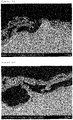
- Figure 2 shows a SEM image of a cross section of the intermediate of sample 1.
- porosity area of pores/total area
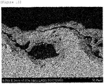
- Table 1 Aqueous solution Heat treatment Raw material for Ni component Raw material for Li component Molar ratio of Li to Ni (Li:Ni) Concentration of nickel acetate (nickel nitrate) (mol/L) Temperature ( ° C) Time (min) Number of times of repeating application to heat treatment Sample 1 Nickel acetate tetrahydrate Lithium nitrate 0.1:1.9 0.56 500 15 20 Sample 2 600 Sample 3 0.3:1.7 500 Sample 4 600 Sample 5 0.5:1.5 500 Sample 6 600 Sample 7 Nickel nitrate hexahydrate 0.1:1.9 2 500 8 Sample 8 600 Sample 9 0.3:1.7 500 Sample 10 600 Sample 11 0.5:1.5 500 Sample 12 600 Table 2 Intermediate layer (oxide) SEM image Composition Thickness ( ⁇ m ) Layer average density (g/cm 3 ) Sample 1 Li 0.1 Ni 1.9 O 2 3.8 5.6 Figure 2 Sample 2 6.5 5.5 Figure 3 Sample 3 Li 0.3 Ni 1.7 O 2 6.7 5.8 Figure 4 Sample 4 6.5 5.8 Figure 5 Sample 5 Li 0.5 Ni 1.5 O
- the concentration of nickel acetate in the aqueous solution was set to 0.56 mol/L.
- expanded mesh (10 cm ⁇ 10 cm, LW ⁇ 3.7 SW ⁇ 0.9 ST ⁇ 0.8 T) made of nickel was prepared.
- This expanded mesh was subjected to a blast treatment (0.3 MPa) with a 60-mesh alumina particle, and was then immersed in 20% by mass hydrochloric acid to be subjected to a chemical etching treatment near the boiling point for 6 minutes.
- the aqueous solution was applied, with a brush, on the surface of the anode substrate after the chemical etching treatment, and the applied aqueous solution was then dried at 80°C for 15 minutes. Subsequently, a heat treatment was performed in an air atmosphere at 600°C for 15 minutes.
- the treatments from applying the aqueous solution to the heat treatment were repeated 20 times to obtain an intermediate having an intermediate layer (composition: Li 0.5 Ni 1.5 O 2 ) formed on the surface of the anode substrate.
- the intermediate layer formed in the resultant intermediate had a thickness of 5.1 to 8.3 ⁇ m and a layer average density of 5.8 to 5.9 g/cm 3 .
- the resultant coating solution was applied on the surface of the intermediate layer in the intermediate in such a way that the amount of the metals per application was 1 g/m 2 , the applied coating solution was dried at room temperature for 10 minutes and then at 60°C for 10 minutes. Subsequently, thermal decomposition of performing a heat treatment in an air circulation type electric furnace at 350°C for 15 minutes was performed.
- the amount of the metals in the formed catalyst layer was 4 g/m 2 .
- a hexaammineiridium solution was applied on the surface of the catalyst layer of the anode for alkaline water electrolysis obtained in Example 1 in such a way that the amount of the metal (Ir) per application was 1 g/m 2 .
- thermal decomposition of performing a heat treatment in an air circulation type electric furnace at 350°C for 15 minutes was performed.
- the treatments from applying the hexaammineiridium solution to the thermal decomposition were repeated 4 times to obtain an anode for alkaline water electrolysis having catalyst layers with a lamination structure having the first catalyst layer (composition: NiCo 2 O 4 ) and the second catalyst layer (composition: IrO 2 ) each formed in the mentioned order on the surface of the intermediate layer.
- the amount of the metal in the formed second catalyst layer was 4 g/m 2 .
- IrHAC iridium hydroxyacetochloride complex
- the anode substrate prepared in Example 1 in such a way that the amount of the metals per application was 1 g/m 2 , the applied coating solution was dried at room temperature for 10 minutes and then at 60°C for 10 minutes. Subsequently, thermal decomposition of performing a heat treatment in an air circulation type electric furnace at 350°C for 15 minutes was performed.
- the treatments from applying the coating solution to the thermal decomposition were repeated 4 times to obtain an anode for alkaline water electrolysis having a catalyst layer (composition: NiCo 2 O 4 ) formed directly on the surface of the anode substrate.
- the amount of the metals in the formed catalyst layer was 4 g/m 2 .
- a small-sized, zero-gap type electrolysis cell was prepared using each produced anode for alkaline water electrolysis as an anode and using a separator and a cathode.
- the electrode area was set to 19 cm 2 .
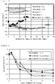
- a 25% by mass KOH aqueous solution was used as an electrolytic solution, and the electrolytic solution was warmed to 80°C to perform electrolysis with a current density of 4 kA/m 2 (Comparative Example 1), 6 kA/m 2 (Example 1), 10 kA/m 2 (Example 2), and 10 kA/m 2 (Example 3) for 6 hours.
- Each test sample before the accelerated life test was first subjected to SSV (Slow Scan Voltammetry) under the condition shown below. The voltage and current density of each sample at the time of generating oxygen was calculated from the result of SSV.
- SSV Small Scan Voltammetry
- the electrode for electrolysis of the present invention is suitable as, for example, an anode for alkaline water electrolysis that constitutes electrolysis facilities and the like using electric power in which there is a large fluctuation in output, such as renewable energy, as a power source.
Landscapes
- Chemical & Material Sciences (AREA)
- Engineering & Computer Science (AREA)
- Materials Engineering (AREA)
- Organic Chemistry (AREA)
- Metallurgy (AREA)
- Chemical Kinetics & Catalysis (AREA)
- Electrochemistry (AREA)
- Inorganic Chemistry (AREA)
- Ceramic Engineering (AREA)
- Physics & Mathematics (AREA)
- Thermal Sciences (AREA)
- General Chemical & Material Sciences (AREA)
- Mechanical Engineering (AREA)
- Electrodes For Compound Or Non-Metal Manufacture (AREA)
- Electrolytic Production Of Non-Metals, Compounds, Apparatuses Therefor (AREA)
Claims (4)
- Electrode pour électrolyse comprenant :un substrat électriquement conducteur dont au moins une surface comprend du nickel ou un alliage à base de nickel ;une couche intermédiaire formée sur la surface du substrat électriquement conducteur et comprenant un oxyde de nickel contenant du lithium représenté par la formule de composition LixNi2-xO2, avec 0,02≤x≤0,5 ; etune couche de catalyseur formée sur une surface de la couche intermédiaire,dans laquelle la couche intermédiaire a une densité moyenne de couche de 5,1 g/cm3 ou plus et 6,67 g/cm3 ou moins et l'épaisseur de la couche intermédiaire est de 0,01 µm ou plus et 100 µm ou moins, et dans laquelle la couche de catalyseur comprend au moins un catalyseur sélectionné dans le groupe consistant en un oxyde de nickel cobalt spinelle, un oxyde de lanthanide nickel cobalt pérovskite, un oxyde d'iridium, un oxyde de ruthénium, et un oxyde de lithium nickel cobalt.
- Procédé de production d'une électrode pour électrolyse, qui est un procédé pour produire l'électrode pour électrolyse selon la revendication 1, le procédé comprenant :une étape d'application d'une solution aqueuse comprenant un ion de lithium et un ion de nickel sur une surface du substrat électriquement conducteur dont au moins une surface comprend du nickel ou un alliage à base de nickel ;une étape de traitement thermique du substrat électriquement conducteur sur la surface duquel est appliquée la solution aqueuse, formant ainsi une couche intermédiaire comprenant un oxyde de nickel contenant du lithium représenté par la formule de composition LixNi2-xO2, avec 0,02≤x≤0,5 sur la surface du substrat électriquement conducteur ; etune étape de formation d'une couche de catalyseur sur une surface de la couche intermédiaire formée.
- Procédé de production d'une électrode pour électrolyse selon la revendication 2, dans lequel la solution aqueuse est préparée par dissolution d'au moins un d'un carboxylate de nickel et d'un carboxylate de lithium dans de l'eau.
- Procédé de production d'une électrode pour électrolyse selon la revendication 2 ou 3, comprenant en outre une étape de réalisation d'un traitement thermique à 450°C ou plus et 600°C ou moins après la formation de la couche de catalyseur.
Applications Claiming Priority (2)
| Application Number | Priority Date | Filing Date | Title |
|---|---|---|---|
| JP2018040569 | 2018-03-07 | ||
| PCT/JP2019/008289 WO2019172160A1 (fr) | 2018-03-07 | 2019-03-04 | Électrode d'électrolyse et son procédé de fabrication |
Publications (3)
| Publication Number | Publication Date |
|---|---|
| EP3763849A1 EP3763849A1 (fr) | 2021-01-13 |
| EP3763849A4 EP3763849A4 (fr) | 2021-12-08 |
| EP3763849B1 true EP3763849B1 (fr) | 2022-11-30 |
Family
ID=67846263
Family Applications (1)
| Application Number | Title | Priority Date | Filing Date |
|---|---|---|---|
| EP19763900.8A Active EP3763849B1 (fr) | 2018-03-07 | 2019-03-04 | Électrode d'électrolyse et son procédé de fabrication |
Country Status (9)
| Country | Link |
|---|---|
| US (1) | US11866834B2 (fr) |
| EP (1) | EP3763849B1 (fr) |
| JP (1) | JP7273024B2 (fr) |
| KR (1) | KR102232627B1 (fr) |
| CN (1) | CN111868308B (fr) |
| CA (1) | CA3093203C (fr) |
| DK (1) | DK3763849T3 (fr) |
| ES (1) | ES2934123T3 (fr) |
| WO (1) | WO2019172160A1 (fr) |
Families Citing this family (19)
| Publication number | Priority date | Publication date | Assignee | Title |
|---|---|---|---|---|
| DK3763849T3 (da) | 2018-03-07 | 2022-12-12 | De Nora Permelec Ltd | Elektrolyseelektrode og fremgangsmåde til fremstilling af samme |
| JP7125707B2 (ja) * | 2018-07-19 | 2022-08-25 | 時空化学株式会社 | 電極の製造方法、電極及び水素の製造方法 |
| JP7474436B2 (ja) * | 2020-03-09 | 2024-04-25 | デノラ・ペルメレック株式会社 | アルカリ水電解方法及びアルカリ水電解用アノード |
| EP4166692B1 (fr) | 2020-06-11 | 2024-09-11 | University of Yamanashi | Catalyseur d'électrode et cellule électrochimique à membrane échangeuse d'anions |
| JP7625204B2 (ja) * | 2020-07-30 | 2025-02-03 | 国立大学法人京都大学 | アルカリ水電解用アノード及びその製造方法 |
| JP6975297B1 (ja) * | 2020-08-28 | 2021-12-01 | デノラ・ペルメレック株式会社 | アルカリ水電解用アノード |
| IT202000020587A1 (it) * | 2020-08-28 | 2022-02-28 | Industrie De Nora Spa | Electrode with enhanced shutdown tolerance- elettrodo con tolleranza agli arresti migliorata |
| JP7694893B2 (ja) * | 2020-10-15 | 2025-06-18 | 国立大学法人京都大学 | アルカリ水電解用アノード及びその製造方法 |
| JP7261418B2 (ja) * | 2020-10-15 | 2023-04-20 | 国立大学法人京都大学 | アルカリ水電解用アノード及びその製造方法 |
| JP7174091B2 (ja) * | 2021-02-24 | 2022-11-17 | デノラ・ペルメレック株式会社 | アルカリ水電解用アノード |
| JP7634400B2 (ja) * | 2021-03-25 | 2025-02-21 | 旭化成株式会社 | 電極、水電解用陽極、電解セル、及び水素の製造方法 |
| IT202100011936A1 (it) * | 2021-05-10 | 2022-11-10 | Industrie De Nora Spa | Elettrodo per l'evoluzione di gas nei processi elettrolitici electrode for gas evolution in electrolytic processes |
| WO2023189350A1 (fr) | 2022-03-31 | 2023-10-05 | デノラ・ペルメレック株式会社 | Électrode d'électrolyse et son procédé de production |
| EP4600408A1 (fr) | 2022-11-10 | 2025-08-13 | De Nora Permelec Ltd | Électrode positive pour électrolyse et son procédé de production |
| CN116288512A (zh) * | 2023-03-06 | 2023-06-23 | 三一氢能有限公司 | 一种碱性水电解制氢用阳极及其制备方法和应用 |
| KR102816925B1 (ko) * | 2023-07-26 | 2025-06-10 | 주식회사 테크로스 | 중간층을 포함하는 수전해 촉매 전극 및 이의 제조 방법 |
| FR3158390B1 (fr) * | 2024-01-11 | 2026-02-27 | Gen Hy Cube | Membrane conductrice anionique, procédé de fabrication d’une telle membrane , cellule électrochimique comprenant une telle membrane et installation comprenant une telle cellule |
| FR3158389A1 (fr) * | 2024-01-11 | 2025-07-18 | Gen-Hy Cube | Membrane conductrice anionique, procédé de fabrication d’une telle membrane , cellule électrochimique comprenant une telle membrane et installation comprenant une telle cellule |
| EP4675010A1 (fr) * | 2024-07-03 | 2026-01-07 | Oberland Mangold GmbH | Couche catalytique pour électrolyse alcaline |
Family Cites Families (17)
| Publication number | Priority date | Publication date | Assignee | Title |
|---|---|---|---|---|
| FR21614E (fr) * | 1953-01-16 | 1921-01-10 | Alphaero Engines Foreign Paten | Perfectionnements aux moteurs à combustion interne |
| GB864457A (en) | 1956-08-23 | 1961-04-06 | Era Patents Ltd | Improvements relating to hydrogen-oxygen cells particularly for use as electrolysers |
| US2928783A (en) | 1956-08-23 | 1960-03-15 | Era Patents Ltd | Porous nickel electrode |
| JP2928783B2 (ja) | 1992-12-28 | 1999-08-03 | 保志 伊須 | ナス類の接木方法とこれに使用する器具 |
| FR2711366B1 (fr) * | 1993-10-20 | 1995-12-15 | Elf Aquitaine | Synthèse du méthylmercaptan à partir du diméthyldisulfure. |
| JPH08106902A (ja) * | 1994-10-03 | 1996-04-23 | Murata Mfg Co Ltd | 電池用薄膜電極及びその製造方法 |
| JP5189781B2 (ja) * | 2007-03-23 | 2013-04-24 | ペルメレック電極株式会社 | 水素発生用電極 |
| KR100864457B1 (ko) | 2007-10-12 | 2008-10-20 | 주식회사 우전그린 | 노면표시 도로 구조물 |
| JP4916040B1 (ja) * | 2011-03-25 | 2012-04-11 | 学校法人同志社 | 電解採取用陽極および該陽極を用いた電解採取法 |
| JP2015086420A (ja) * | 2013-10-29 | 2015-05-07 | 国立大学法人横浜国立大学 | アルカリ水電解用陽極 |
| DE102014222372A1 (de) | 2014-11-03 | 2016-05-04 | Bayerische Motoren Werke Aktiengesellschaft | Elektrolyt für Lithium-basierte Energiespeicher |
| JP6615682B2 (ja) * | 2016-04-12 | 2019-12-04 | デノラ・ペルメレック株式会社 | アルカリ水電解用陽極及びアルカリ水電解用陽極の製造方法 |
| CA3036352C (fr) | 2016-09-09 | 2020-09-15 | De Nora Permelec Ltd | Methode de production d'anode d'electrolyse d'eau alcaline et anode destinee a l'electrolyse d'eau alcaline |
| JP2018178221A (ja) | 2017-04-18 | 2018-11-15 | 株式会社豊田自動織機 | 脂肪酸塩の製造方法 |
| DK3763849T3 (da) | 2018-03-07 | 2022-12-12 | De Nora Permelec Ltd | Elektrolyseelektrode og fremgangsmåde til fremstilling af samme |
| WO2020032256A1 (fr) | 2018-08-09 | 2020-02-13 | 国立研究開発法人理化学研究所 | Procédé et appareil d'électrolyse de l'eau, et procédé de détermination du potentiel d'attaque d'électrolyse de l'eau |
| JP6975297B1 (ja) | 2020-08-28 | 2021-12-01 | デノラ・ペルメレック株式会社 | アルカリ水電解用アノード |
-
2019
- 2019-03-04 DK DK19763900.8T patent/DK3763849T3/da active
- 2019-03-04 US US16/975,868 patent/US11866834B2/en active Active
- 2019-03-04 ES ES19763900T patent/ES2934123T3/es active Active
- 2019-03-04 CN CN201980017425.4A patent/CN111868308B/zh active Active
- 2019-03-04 KR KR1020207028348A patent/KR102232627B1/ko active Active
- 2019-03-04 CA CA3093203A patent/CA3093203C/fr active Active
- 2019-03-04 EP EP19763900.8A patent/EP3763849B1/fr active Active
- 2019-03-04 WO PCT/JP2019/008289 patent/WO2019172160A1/fr not_active Ceased
- 2019-03-04 JP JP2020505004A patent/JP7273024B2/ja active Active
Also Published As
| Publication number | Publication date |
|---|---|
| KR102232627B1 (ko) | 2021-03-25 |
| US11866834B2 (en) | 2024-01-09 |
| US20200407860A1 (en) | 2020-12-31 |
| CA3093203A1 (fr) | 2019-09-12 |
| CN111868308B (zh) | 2021-07-20 |
| EP3763849A4 (fr) | 2021-12-08 |
| DK3763849T3 (da) | 2022-12-12 |
| CA3093203C (fr) | 2021-03-16 |
| ES2934123T3 (es) | 2023-02-17 |
| EP3763849A1 (fr) | 2021-01-13 |
| CN111868308A (zh) | 2020-10-30 |
| JP7273024B2 (ja) | 2023-05-12 |
| JPWO2019172160A1 (ja) | 2021-02-18 |
| KR20200119342A (ko) | 2020-10-19 |
| WO2019172160A1 (fr) | 2019-09-12 |
Similar Documents
| Publication | Publication Date | Title |
|---|---|---|
| EP3763849B1 (fr) | Électrode d'électrolyse et son procédé de fabrication | |
| CN109689937B (zh) | 碱性水电解用阳极的制造方法和碱性水电解用阳极 | |
| US11692276B2 (en) | Alkaline water electrolysis method, and anode for alkaline water electrolysis | |
| US11390958B2 (en) | Alkaline water electrolysis method and alkaline water electrolysis anode | |
| US11965256B2 (en) | Anode for alkaline water electrolysis and method for producing same | |
| EP4190944B1 (fr) | Anode pour électrolyse d'eau alcaline et son procédé de production | |
| EP4600408A1 (fr) | Électrode positive pour électrolyse et son procédé de production | |
| EP4474530A1 (fr) | Électrode d'électrolyse et son procédé de production | |
| CA3186983C (fr) | Anode pour l'electrolyse a l'eau alcaline et methode de production connexe |
Legal Events
| Date | Code | Title | Description |
|---|---|---|---|
| STAA | Information on the status of an ep patent application or granted ep patent |
Free format text: STATUS: THE INTERNATIONAL PUBLICATION HAS BEEN MADE |
|
| PUAI | Public reference made under article 153(3) epc to a published international application that has entered the european phase |
Free format text: ORIGINAL CODE: 0009012 |
|
| STAA | Information on the status of an ep patent application or granted ep patent |
Free format text: STATUS: REQUEST FOR EXAMINATION WAS MADE |
|
| 17P | Request for examination filed |
Effective date: 20200907 |
|
| AK | Designated contracting states |
Kind code of ref document: A1 Designated state(s): AL AT BE BG CH CY CZ DE DK EE ES FI FR GB GR HR HU IE IS IT LI LT LU LV MC MK MT NL NO PL PT RO RS SE SI SK SM TR |
|
| AX | Request for extension of the european patent |
Extension state: BA ME |
|
| DAV | Request for validation of the european patent (deleted) | ||
| DAX | Request for extension of the european patent (deleted) | ||
| REG | Reference to a national code |
Ref country code: DE Ref legal event code: R079 Ref document number: 602019022584 Country of ref document: DE Free format text: PREVIOUS MAIN CLASS: C25B0011040000 Ipc: C25B0001040000 |
|
| A4 | Supplementary search report drawn up and despatched |
Effective date: 20211108 |
|
| RIC1 | Information provided on ipc code assigned before grant |
Ipc: C25B 11/093 20210101ALI20211102BHEP Ipc: C25B 11/077 20210101ALI20211102BHEP Ipc: C25B 11/075 20210101ALI20211102BHEP Ipc: C25B 11/069 20210101ALI20211102BHEP Ipc: C25B 11/052 20210101ALI20211102BHEP Ipc: C25B 1/04 20210101AFI20211102BHEP |
|
| GRAP | Despatch of communication of intention to grant a patent |
Free format text: ORIGINAL CODE: EPIDOSNIGR1 |
|
| STAA | Information on the status of an ep patent application or granted ep patent |
Free format text: STATUS: GRANT OF PATENT IS INTENDED |
|
| INTG | Intention to grant announced |
Effective date: 20220720 |
|
| RIN1 | Information on inventor provided before grant (corrected) |
Inventor name: NAKAI, TAKAAKI Inventor name: TSUJII, FUMIYA Inventor name: ZAENAL, AWALUDIN Inventor name: KATO, AKIHIRO Inventor name: NISHIKI, YOSHINORI Inventor name: TANIGUCHI, TATSUYA Inventor name: NAGASHIMA, IKUO Inventor name: KURODA, YOSHIYUKI Inventor name: MITSUSHIMA, SHIGENORI |
|
| GRAS | Grant fee paid |
Free format text: ORIGINAL CODE: EPIDOSNIGR3 |
|
| GRAA | (expected) grant |
Free format text: ORIGINAL CODE: 0009210 |
|
| STAA | Information on the status of an ep patent application or granted ep patent |
Free format text: STATUS: THE PATENT HAS BEEN GRANTED |
|
| AK | Designated contracting states |
Kind code of ref document: B1 Designated state(s): AL AT BE BG CH CY CZ DE DK EE ES FI FR GB GR HR HU IE IS IT LI LT LU LV MC MK MT NL NO PL PT RO RS SE SI SK SM TR |
|
| REG | Reference to a national code |
Ref country code: CH Ref legal event code: EP Ref country code: GB Ref legal event code: FG4D |
|
| REG | Reference to a national code |
Ref country code: DK Ref legal event code: T3 Effective date: 20221206 |
|
| REG | Reference to a national code |
Ref country code: AT Ref legal event code: REF Ref document number: 1534736 Country of ref document: AT Kind code of ref document: T Effective date: 20221215 |
|
| REG | Reference to a national code |
Ref country code: NL Ref legal event code: FP Ref country code: IE Ref legal event code: FG4D |
|
| REG | Reference to a national code |
Ref country code: DE Ref legal event code: R096 Ref document number: 602019022584 Country of ref document: DE |
|
| REG | Reference to a national code |
Ref country code: SE Ref legal event code: TRGR |
|
| REG | Reference to a national code |
Ref country code: NO Ref legal event code: T2 Effective date: 20221130 |
|
| REG | Reference to a national code |
Ref country code: ES Ref legal event code: FG2A Ref document number: 2934123 Country of ref document: ES Kind code of ref document: T3 Effective date: 20230217 |
|
| REG | Reference to a national code |
Ref country code: LT Ref legal event code: MG9D |
|
| PG25 | Lapsed in a contracting state [announced via postgrant information from national office to epo] |
Ref country code: PT Free format text: LAPSE BECAUSE OF FAILURE TO SUBMIT A TRANSLATION OF THE DESCRIPTION OR TO PAY THE FEE WITHIN THE PRESCRIBED TIME-LIMIT Effective date: 20230331 Ref country code: LT Free format text: LAPSE BECAUSE OF FAILURE TO SUBMIT A TRANSLATION OF THE DESCRIPTION OR TO PAY THE FEE WITHIN THE PRESCRIBED TIME-LIMIT Effective date: 20221130 Ref country code: FI Free format text: LAPSE BECAUSE OF FAILURE TO SUBMIT A TRANSLATION OF THE DESCRIPTION OR TO PAY THE FEE WITHIN THE PRESCRIBED TIME-LIMIT Effective date: 20221130 |
|
| REG | Reference to a national code |
Ref country code: AT Ref legal event code: MK05 Ref document number: 1534736 Country of ref document: AT Kind code of ref document: T Effective date: 20221130 |
|
| PG25 | Lapsed in a contracting state [announced via postgrant information from national office to epo] |
Ref country code: RS Free format text: LAPSE BECAUSE OF FAILURE TO SUBMIT A TRANSLATION OF THE DESCRIPTION OR TO PAY THE FEE WITHIN THE PRESCRIBED TIME-LIMIT Effective date: 20221130 Ref country code: PL Free format text: LAPSE BECAUSE OF FAILURE TO SUBMIT A TRANSLATION OF THE DESCRIPTION OR TO PAY THE FEE WITHIN THE PRESCRIBED TIME-LIMIT Effective date: 20221130 Ref country code: LV Free format text: LAPSE BECAUSE OF FAILURE TO SUBMIT A TRANSLATION OF THE DESCRIPTION OR TO PAY THE FEE WITHIN THE PRESCRIBED TIME-LIMIT Effective date: 20221130 Ref country code: IS Free format text: LAPSE BECAUSE OF FAILURE TO SUBMIT A TRANSLATION OF THE DESCRIPTION OR TO PAY THE FEE WITHIN THE PRESCRIBED TIME-LIMIT Effective date: 20230330 Ref country code: HR Free format text: LAPSE BECAUSE OF FAILURE TO SUBMIT A TRANSLATION OF THE DESCRIPTION OR TO PAY THE FEE WITHIN THE PRESCRIBED TIME-LIMIT Effective date: 20221130 Ref country code: GR Free format text: LAPSE BECAUSE OF FAILURE TO SUBMIT A TRANSLATION OF THE DESCRIPTION OR TO PAY THE FEE WITHIN THE PRESCRIBED TIME-LIMIT Effective date: 20230301 |
|
| P01 | Opt-out of the competence of the unified patent court (upc) registered |
Effective date: 20230514 |
|
| PG25 | Lapsed in a contracting state [announced via postgrant information from national office to epo] |
Ref country code: SM Free format text: LAPSE BECAUSE OF FAILURE TO SUBMIT A TRANSLATION OF THE DESCRIPTION OR TO PAY THE FEE WITHIN THE PRESCRIBED TIME-LIMIT Effective date: 20221130 Ref country code: RO Free format text: LAPSE BECAUSE OF FAILURE TO SUBMIT A TRANSLATION OF THE DESCRIPTION OR TO PAY THE FEE WITHIN THE PRESCRIBED TIME-LIMIT Effective date: 20221130 Ref country code: EE Free format text: LAPSE BECAUSE OF FAILURE TO SUBMIT A TRANSLATION OF THE DESCRIPTION OR TO PAY THE FEE WITHIN THE PRESCRIBED TIME-LIMIT Effective date: 20221130 Ref country code: CZ Free format text: LAPSE BECAUSE OF FAILURE TO SUBMIT A TRANSLATION OF THE DESCRIPTION OR TO PAY THE FEE WITHIN THE PRESCRIBED TIME-LIMIT Effective date: 20221130 Ref country code: AT Free format text: LAPSE BECAUSE OF FAILURE TO SUBMIT A TRANSLATION OF THE DESCRIPTION OR TO PAY THE FEE WITHIN THE PRESCRIBED TIME-LIMIT Effective date: 20221130 |
|
| PG25 | Lapsed in a contracting state [announced via postgrant information from national office to epo] |
Ref country code: SK Free format text: LAPSE BECAUSE OF FAILURE TO SUBMIT A TRANSLATION OF THE DESCRIPTION OR TO PAY THE FEE WITHIN THE PRESCRIBED TIME-LIMIT Effective date: 20221130 Ref country code: AL Free format text: LAPSE BECAUSE OF FAILURE TO SUBMIT A TRANSLATION OF THE DESCRIPTION OR TO PAY THE FEE WITHIN THE PRESCRIBED TIME-LIMIT Effective date: 20221130 |
|
| REG | Reference to a national code |
Ref country code: DE Ref legal event code: R097 Ref document number: 602019022584 Country of ref document: DE |
|
| PLBE | No opposition filed within time limit |
Free format text: ORIGINAL CODE: 0009261 |
|
| STAA | Information on the status of an ep patent application or granted ep patent |
Free format text: STATUS: NO OPPOSITION FILED WITHIN TIME LIMIT |
|
| PG25 | Lapsed in a contracting state [announced via postgrant information from national office to epo] |
Ref country code: MC Free format text: LAPSE BECAUSE OF FAILURE TO SUBMIT A TRANSLATION OF THE DESCRIPTION OR TO PAY THE FEE WITHIN THE PRESCRIBED TIME-LIMIT Effective date: 20221130 |
|
| REG | Reference to a national code |
Ref country code: CH Ref legal event code: PL |
|
| 26N | No opposition filed |
Effective date: 20230831 |
|
| PG25 | Lapsed in a contracting state [announced via postgrant information from national office to epo] |
Ref country code: SI Free format text: LAPSE BECAUSE OF FAILURE TO SUBMIT A TRANSLATION OF THE DESCRIPTION OR TO PAY THE FEE WITHIN THE PRESCRIBED TIME-LIMIT Effective date: 20221130 |
|
| REG | Reference to a national code |
Ref country code: DE Ref legal event code: R081 Ref document number: 602019022584 Country of ref document: DE Owner name: KAWASAKI JUKOGYO KABUSHIKI KAISHA, KOBE-SHI, JP Free format text: FORMER OWNERS: DE NORA PERMELEC LTD., FUJISAWA-SHI, KANAGAWA, JP; KAWASAKI JUKOGYO KABUSHIKI KAISHA, KOBE-SHI, HYOGO, JP; NATIONAL UNIVERSITY CORPORATION YOKOHAMA NATIONAL UNIVERSITY, YOKOHAMA-SHI, KANAGAWA, JP Ref country code: DE Ref legal event code: R081 Ref document number: 602019022584 Country of ref document: DE Owner name: DE NORA PERMELEC LTD., FUJISAWA-SHI, JP Free format text: FORMER OWNERS: DE NORA PERMELEC LTD., FUJISAWA-SHI, KANAGAWA, JP; KAWASAKI JUKOGYO KABUSHIKI KAISHA, KOBE-SHI, HYOGO, JP; NATIONAL UNIVERSITY CORPORATION YOKOHAMA NATIONAL UNIVERSITY, YOKOHAMA-SHI, KANAGAWA, JP |
|
| REG | Reference to a national code |
Ref country code: NO Ref legal event code: CHAD Owner name: DE NORA PERMELEC LTD, JP |
|
| REG | Reference to a national code |
Ref country code: NL Ref legal event code: PD Owner name: KAWASAKI JUKOGYO KABUSHIKI KAISHA; JP Free format text: DETAILS ASSIGNMENT: CHANGE OF OWNER(S), ASSIGNMENT; FORMER OWNER NAME: NATIONAL UNIVERSITY CORPORATION YOKOHAMA NATIONAL UNIVERSITY Effective date: 20231207 Ref country code: GB Ref legal event code: 732E Free format text: REGISTERED BETWEEN 20231116 AND 20231122 |
|
| PG25 | Lapsed in a contracting state [announced via postgrant information from national office to epo] |
Ref country code: LU Free format text: LAPSE BECAUSE OF NON-PAYMENT OF DUE FEES Effective date: 20230304 |
|
| REG | Reference to a national code |
Ref country code: IE Ref legal event code: MM4A |
|
| PG25 | Lapsed in a contracting state [announced via postgrant information from national office to epo] |
Ref country code: LI Free format text: LAPSE BECAUSE OF NON-PAYMENT OF DUE FEES Effective date: 20230331 Ref country code: IE Free format text: LAPSE BECAUSE OF NON-PAYMENT OF DUE FEES Effective date: 20230304 Ref country code: CH Free format text: LAPSE BECAUSE OF NON-PAYMENT OF DUE FEES Effective date: 20230331 |
|
| REG | Reference to a national code |
Ref country code: BE Ref legal event code: PD Owner name: KAWASAKI JUKOGYO KABUSHIKI KAISHA; JP Free format text: DETAILS ASSIGNMENT: CHANGE OF OWNER(S), ASSIGNMENT; FORMER OWNER NAME: NATIONAL UNIVERSITY CORPORATION YOKOHAMA NATIONAL UNIVERSITY Effective date: 20240103 |
|
| REG | Reference to a national code |
Ref country code: ES Ref legal event code: PC2A Owner name: KAWASAKI JUKOGYO KABUSHIKI KAISHA Effective date: 20240718 |
|
| PG25 | Lapsed in a contracting state [announced via postgrant information from national office to epo] |
Ref country code: BG Free format text: LAPSE BECAUSE OF FAILURE TO SUBMIT A TRANSLATION OF THE DESCRIPTION OR TO PAY THE FEE WITHIN THE PRESCRIBED TIME-LIMIT Effective date: 20221130 |
|
| PG25 | Lapsed in a contracting state [announced via postgrant information from national office to epo] |
Ref country code: BG Free format text: LAPSE BECAUSE OF FAILURE TO SUBMIT A TRANSLATION OF THE DESCRIPTION OR TO PAY THE FEE WITHIN THE PRESCRIBED TIME-LIMIT Effective date: 20221130 |
|
| PGFP | Annual fee paid to national office [announced via postgrant information from national office to epo] |
Ref country code: ES Payment date: 20250403 Year of fee payment: 7 |
|
| PG25 | Lapsed in a contracting state [announced via postgrant information from national office to epo] |
Ref country code: CY Free format text: LAPSE BECAUSE OF FAILURE TO SUBMIT A TRANSLATION OF THE DESCRIPTION OR TO PAY THE FEE WITHIN THE PRESCRIBED TIME-LIMIT; INVALID AB INITIO Effective date: 20190304 |
|
| PG25 | Lapsed in a contracting state [announced via postgrant information from national office to epo] |
Ref country code: HU Free format text: LAPSE BECAUSE OF FAILURE TO SUBMIT A TRANSLATION OF THE DESCRIPTION OR TO PAY THE FEE WITHIN THE PRESCRIBED TIME-LIMIT; INVALID AB INITIO Effective date: 20190304 |
|
| PG25 | Lapsed in a contracting state [announced via postgrant information from national office to epo] |
Ref country code: TR Free format text: LAPSE BECAUSE OF FAILURE TO SUBMIT A TRANSLATION OF THE DESCRIPTION OR TO PAY THE FEE WITHIN THE PRESCRIBED TIME-LIMIT Effective date: 20221130 |
|
| PGFP | Annual fee paid to national office [announced via postgrant information from national office to epo] |
Ref country code: NL Payment date: 20260213 Year of fee payment: 8 |
|
| REG | Reference to a national code |
Ref country code: ES Ref legal event code: PC2A Owner name: KAWASAKI JUKOGYO KABUSHIKI KAISHA Effective date: 20260323 |
|
| PGFP | Annual fee paid to national office [announced via postgrant information from national office to epo] |
Ref country code: SE Payment date: 20260211 Year of fee payment: 8 |
|
| PGFP | Annual fee paid to national office [announced via postgrant information from national office to epo] |
Ref country code: GB Payment date: 20260202 Year of fee payment: 8 |
|
| PGFP | Annual fee paid to national office [announced via postgrant information from national office to epo] |
Ref country code: NO Payment date: 20260310 Year of fee payment: 8 Ref country code: DE Payment date: 20260128 Year of fee payment: 8 Ref country code: DK Payment date: 20260313 Year of fee payment: 8 |
|
| PGFP | Annual fee paid to national office [announced via postgrant information from national office to epo] |
Ref country code: BE Payment date: 20260217 Year of fee payment: 8 Ref country code: IT Payment date: 20260220 Year of fee payment: 8 |
|
| PGFP | Annual fee paid to national office [announced via postgrant information from national office to epo] |
Ref country code: FR Payment date: 20260209 Year of fee payment: 8 |