EP4249719A1 - Profilé de raccordement - Google Patents
Profilé de raccordement Download PDFInfo
- Publication number
- EP4249719A1 EP4249719A1 EP23162321.6A EP23162321A EP4249719A1 EP 4249719 A1 EP4249719 A1 EP 4249719A1 EP 23162321 A EP23162321 A EP 23162321A EP 4249719 A1 EP4249719 A1 EP 4249719A1
- Authority
- EP
- European Patent Office
- Prior art keywords
- profile strip
- base leg
- connection profile
- leg
- elastic
- Prior art date
- Legal status (The legal status is an assumption and is not a legal conclusion. Google has not performed a legal analysis and makes no representation as to the accuracy of the status listed.)
- Pending
Links
- 239000002390 adhesive tape Substances 0.000 claims abstract description 20
- 239000012790 adhesive layer Substances 0.000 claims abstract description 10
- 230000001681 protective effect Effects 0.000 claims description 10
- 238000004026 adhesive bonding Methods 0.000 claims description 3
- 239000013589 supplement Substances 0.000 claims 1
- XLYOFNOQVPJJNP-UHFFFAOYSA-N water Substances O XLYOFNOQVPJJNP-UHFFFAOYSA-N 0.000 description 8
- 239000011505 plaster Substances 0.000 description 6
- 238000007789 sealing Methods 0.000 description 4
- 229910052782 aluminium Inorganic materials 0.000 description 3
- XAGFODPZIPBFFR-UHFFFAOYSA-N aluminium Chemical compound [Al] XAGFODPZIPBFFR-UHFFFAOYSA-N 0.000 description 3
- 230000000694 effects Effects 0.000 description 3
- 239000000463 material Substances 0.000 description 3
- 238000004140 cleaning Methods 0.000 description 2
- 239000006260 foam Substances 0.000 description 2
- 238000009413 insulation Methods 0.000 description 2
- 230000035515 penetration Effects 0.000 description 2
- 239000000853 adhesive Substances 0.000 description 1
- 230000001070 adhesive effect Effects 0.000 description 1
- 238000011109 contamination Methods 0.000 description 1
- 230000008878 coupling Effects 0.000 description 1
- 238000010168 coupling process Methods 0.000 description 1
- 238000005859 coupling reaction Methods 0.000 description 1
- 230000007547 defect Effects 0.000 description 1
- 239000004744 fabric Substances 0.000 description 1
- 239000011888 foil Substances 0.000 description 1
- 239000010410 layer Substances 0.000 description 1
- 229910052751 metal Inorganic materials 0.000 description 1
- 239000002184 metal Substances 0.000 description 1
- 238000000034 method Methods 0.000 description 1
- 230000000149 penetrating effect Effects 0.000 description 1
- 230000003014 reinforcing effect Effects 0.000 description 1
- 238000000926 separation method Methods 0.000 description 1
- 230000007704 transition Effects 0.000 description 1
Images




Classifications
-
- E—FIXED CONSTRUCTIONS
- E04—BUILDING
- E04F—FINISHING WORK ON BUILDINGS, e.g. STAIRS, FLOORS
- E04F13/00—Coverings or linings, e.g. for walls or ceilings
- E04F13/02—Coverings or linings, e.g. for walls or ceilings of plastic materials hardening after applying, e.g. plaster
- E04F13/04—Bases for plaster
- E04F13/06—Edge-protecting borders
-
- E—FIXED CONSTRUCTIONS
- E04—BUILDING
- E04F—FINISHING WORK ON BUILDINGS, e.g. STAIRS, FLOORS
- E04F13/00—Coverings or linings, e.g. for walls or ceilings
- E04F13/02—Coverings or linings, e.g. for walls or ceilings of plastic materials hardening after applying, e.g. plaster
- E04F13/04—Bases for plaster
- E04F13/06—Edge-protecting borders
- E04F13/068—Edge-protecting borders combined with mesh material or the like to allow plaster to bond therewith
-
- E—FIXED CONSTRUCTIONS
- E06—DOORS, WINDOWS, SHUTTERS, OR ROLLER BLINDS IN GENERAL; LADDERS
- E06B—FIXED OR MOVABLE CLOSURES FOR OPENINGS IN BUILDINGS, VEHICLES, FENCES OR LIKE ENCLOSURES IN GENERAL, e.g. DOORS, WINDOWS, BLINDS, GATES
- E06B1/00—Border constructions of openings in walls, floors, or ceilings; Frames to be rigidly mounted in such openings
- E06B1/62—Tightening or covering joints between the border of openings and the frame or between contiguous frames
-
- E—FIXED CONSTRUCTIONS
- E04—BUILDING
- E04F—FINISHING WORK ON BUILDINGS, e.g. STAIRS, FLOORS
- E04F13/00—Coverings or linings, e.g. for walls or ceilings
- E04F13/02—Coverings or linings, e.g. for walls or ceilings of plastic materials hardening after applying, e.g. plaster
- E04F13/04—Bases for plaster
- E04F13/06—Edge-protecting borders
- E04F2013/065—Edge-protecting borders for lower edges of outer insulation layers
-
- E—FIXED CONSTRUCTIONS
- E06—DOORS, WINDOWS, SHUTTERS, OR ROLLER BLINDS IN GENERAL; LADDERS
- E06B—FIXED OR MOVABLE CLOSURES FOR OPENINGS IN BUILDINGS, VEHICLES, FENCES OR LIKE ENCLOSURES IN GENERAL, e.g. DOORS, WINDOWS, BLINDS, GATES
- E06B1/00—Border constructions of openings in walls, floors, or ceilings; Frames to be rigidly mounted in such openings
- E06B1/62—Tightening or covering joints between the border of openings and the frame or between contiguous frames
- E06B2001/624—Tightening or covering joints between the border of openings and the frame or between contiguous frames with parts to be embedded in the stucco layer or otherwise linked to this layer
Definitions
- the invention relates to a connection profile strip with the features of the introductory part of claim 1.
- connection profile strips which are intended as window connection profile strips or plaster sealing profile strips for windows and/or doors with an attachment shell made of metal (aluminum) or plastic, are known.
- connection profile for built-in parts adjacent to insulation layers with plaster, such as window frames, door frames or the like.
- An attachment shell made of aluminum or plastic is preferably attached to the built-in part.
- the known connection profile has a base leg attached to the built-in part and is equipped with a plastering leg which has a cover web that overlaps the reveal-side edge of the facing shell.
- a disadvantage of the known profiles of the generic type is that a shadow gap arises between the connecting profile and the facing shell, particularly when movements occur between the individual components. Water can penetrate through this joint to the adhesive surface of the connecting profile strip on the window or door frame. Since it is not possible to see the bonding of the connection profile to the frame of the window or door, it cannot be determined whether the bonding is correct, i.e. whether a permanent and proper bonding is guaranteed.
- connection profile is detached from the frame of the window or door or if the bonding is inadequate, water can penetrate into the facade or into the structure of the building behind it. This water can damage the facade and the structure.
- connection profile strip As mentioned, a detachment of the known connection profile from the frame of a window or door and/or poor gluing of the connection profile strip cannot be seen from the outside, so that this defect remains undetected until visible damage is caused by penetrating moisture (water).
- the invention is based on the object of providing a connection profile strip of the type mentioned at the beginning, which avoids the problems described.
- connection profile strip according to the invention are the subject of the subclaims.
- connection profile strip is glued to the facing shell (made of aluminum or plastic) and a band is also provided which is to be attached to the base leg of the connection profile strip and the frame of the window or door and forms a seal. This creates a tight seal on the window or door frame.
- connection profile strip The band provided in the connection profile strip according to the invention and forming a seal can be glued to the connection profile strip or attached by coextrusion.
- connection profile strip the band forming a seal can be glued to the frame of the window or door, for example with an adhesive tape.
- connection profile strip With the connection profile strip according to the invention, there is no open joint between the connection profile strip and the facing shell, through which water can enter the floor of the window or door.
- a further advantage is that because of the flexible tape glued to the frame of the window or door, movements that occur between the frame of the window or door, the facing shell and/or the facade can be compensated for.
- the connecting profile strip according to the invention When using the connecting profile strip according to the invention, there are two seals between the connecting profile strip and the floor of the window or door and the facing shell: a primary seal, which is formed at least by the bond between the base leg of the connecting profile strip and the facing shell, and a secondary seal, which is formed by the (Foil) tape that extends from the base leg of the connecting profile strip to the floor of the window or door is formed.
- the connecting profile strip according to the invention has, in addition to the bonding between the connecting profile strip and the facing shell, an elastic strip which rests against the facing shell in the position of use, the primary seal is primarily, i.e. mainly, formed by the elastic strip which seals against the facing shell. In this case, the bond between the connecting profile strip and the facing shell supports the primary seal.
- the primary seal is formed solely by the bonding, for example comprising an elastic adhesive tape, between the connecting profile strip and the facing shell.
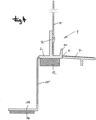
- Connection profile strip 1 shown has a base leg 2 and a plastering leg 3.
- a reinforcing fabric 5 is attached to the plaster leg 3 via a plastic strip 4.
- a protective leg 7 is provided at the lower end of the plastering leg 3 or at the edge of the base leg 2 located there.
- the elastic strip 9 is in the in Fig. 1 shown, not yet installed state of the connecting profile strip 1 is held in its compressed (compacted) state by a plate 10.
- the edges of the plate 10 running in the direction of the longitudinal extent of the connecting profile strip 1 are accommodated in grooves 11 in the base leg 2 and in the protective leg 7 that are open to one another. If the protective leg 7 is removed after installing the connection profile strip 1, the plate 10 is also removed so that the elastic strip 9 can expand.
- an elastic adhesive tape 12 in particular a double-sided adhesive tape, is attached.
- the adhesive tape 12 forms the in Fig. 1 and 2 shown embodiment of the connecting profile strip 1 together with the elastic strip 9, a primary seal 30 between the connecting profile strip 1 and the attachment shell 22.
- the primary seal 30 is primarily formed by the elastic strip 9 and supported by the elastic adhesive tape 12.
- connection profile strips 1 At the in Fig. 1 On the upper side of the base leg 2, a longitudinal groove 13 and a barb 14 are provided. A coupling (not shown) between adjoining connection profile strips 1 can be inserted into the space 17 formed in this way in order to connect adjacent connection profile strips 1 to one another and to seal the joints between connection profile strips 1.
- connection profile strip 1 In the longitudinal edge of the base leg 2, which lies opposite the longitudinal edge on which the plastering leg 3 is provided, is in the in Fig. 1 shown embodiment of the connection profile strip 1, a flexible band 15 (film made of soft PVC) is provided.
- the band 15 serves as a seal (secondary seal 40) between the Connection profile strip 1 and an adjacent component, such as a floor 21 of a window or a door.
- an adhesive layer 16 for example in the form of a double-sided adhesive tape.
- connection profile strip 1 corresponds to that in Fig. 1 shown embodiment with the proviso that the sealing element (secondary seal 40) is formed by a flexible band 15 extruded onto the base leg 2, on the free edge of which an angle profile 18 carrying the adhesive layer 16 is provided.
- the band 15 is made of flexible material, whereas the angle profile 18 is made of rigid material.
- the band 15 is made of soft PVC, whereas the angle profile 18 can be made of hard PVC.
- connection profile strip 1 As well as at the in Fig. 2
- a cleaning edge 20 is provided, which protrudes from the base leg 2.
- FIG. 3 The embodiment shown of a connecting profile strip 1 according to the invention is a simplified embodiment in which no elastic strip 9 is provided on the base leg 2 but only an elastic adhesive tape 12, which forms the primary seal in this embodiment.
- On the base leg 2 is - similar to that in Fig. 1 embodiment shown - an elastic band 15, which carries the adhesive layer 16, is provided as a sealing element.
- a protective leg 7 which has a tear-off point 6 formed separation point is connected to the base leg 2, so that the cleaning edge 20 results after the protective leg 7 has been separated.
- connection profile strip 1 corresponds to that in Fig. 3 shown embodiment with the proviso that the band 15 on the base leg 2 - similar Fig. 2 - is extruded.
- the band 15 is provided with the angle profile 18 and the adhesive layer 16.
- Fig. 5 shows how a connection profile strip 1 (similar to that in Fig. 1 embodiment shown) is arranged on a floor 21 of a window (or a door), with an attachment shell 22 being provided on the floor 21. It can be seen that the tape 15 is glued to the stick 21 via the adhesive layer 16. The elastic strip 9 is expanded and lies sealingly against the attachment shell 22 (primary seal 30). In addition, it can be seen that the base leg 2 is connected to the attachment shell 22 via the elastic adhesive tape 12.
- Fig. 6 shows - like Fig. 5 - like a connection profile strip 1 in Fig. 2 shown embodiment is arranged in the installed position on the attachment shell 22 and on the stick 21.
- the elastic strip 9 provides a secure seal ("primary seal 30"), even if there are relative movements between the facing shell 22 and/or the stick 21 to which the facing shell 22 is attached and an adjacent part of the building . If, for some reason, the bond between the elastic adhesive tape 12 and the facing shell 22 comes loose and the primary seal 30 formed by the elastic strip 9 is ineffective, the tape 15, which is glued to the stick 21, will still provide a secure seal
- connection profile strip 1 (Secondary seal 40) and reliably prevents the penetration of water into insulation and/or into adjacent structural parts. This applies to all embodiments of the connection profile strip 1 according to the invention.
- connection profile strip 1 When using a connection profile strip 1 according to the invention, the following procedure can be carried out, for example.
- the tape 15 is attached to the in. using the adhesive layer 16 Fig. 5 upward-facing surface 23 of the floor 21 of the window or door.
- the next step is to separate the protective leg 7 after the plaster has been applied, so that on the one hand the plaster edge 20 is exposed on the base leg 2 and on the other hand the plate 10 is removed (at the same time as the protective leg 7 is separated).
- This allows the elastic strip 9 to expand (expand) and perform its sealing function (primary seal 30).
- the free surface of the elastic strip 9 then rests on the outside of the attachment shell 22.
- the Fig. 5 and 6 show the primary seal 30 and the secondary seal 40.
- the primary seal 30 is used in the embodiment of connecting profile strips 1 Fig. 1 and 2 formed by the elastic strip 9 and supported by the bonding of the elastic adhesive tape 12 to the facing shell 22.
- the secondary seal 40 is formed by the band 15, which is fastened with one longitudinal edge to the base leg 2 and with the other longitudinal edge to the edge surface 23 of the stick 21.
- the band 15 is made of flexible material and is either elastic at least transversely to its longitudinal extent or is - as in the Fig. 5 and 6 indicated by dashed lines - wavy at least once (i.e. curved "loop-like" one or more times).
- the corrugation is aligned parallel to the direction of the longitudinal extent of the connecting profile strip 1.
- the band 15, which forms the secondary seal 40 can be both transversely elastic and corrugated in an embodiment contemplated within the scope of the invention.
- the effect of the secondary seal 40 remains even if the bond between the connecting profile strip 1 and the attachment shell 22 has dissolved and in the embodiments of the connecting profile strip 1 according to Fig. 1 and 2 the elastic strip 9 no longer seals. The then greater distance between the connecting profile strip 1 and the facing shell 22 merely causes the band 15 to stretch and/or stretch.
- the band 15 of the secondary seal 40 also has the advantageous effect that the function of the secondary seal 40 is given even with different distances between the stick 21 and the attachment shell 22.
- a connecting profile strip 1 comprises a base leg 2 and a plastering leg 3.
- An elastic strip 9 is provided on the base leg 2, which rests on an attachment shell 22 of a floor 21 of a window or a door, forming a primary seal 30.
- the base leg 2 of the connecting profile strip 1 is glued to the attachment shell 22 using an elastic adhesive tape 12.
- a band 15 is attached to the base leg 2, the free edge of which is glued to the stick 21 via an adhesive layer 16 to form a secondary seal 40.
Landscapes
- Engineering & Computer Science (AREA)
- Architecture (AREA)
- Civil Engineering (AREA)
- Structural Engineering (AREA)
- Specific Sealing Or Ventilating Devices For Doors And Windows (AREA)
- Building Environments (AREA)
- Door And Window Frames Mounted To Openings (AREA)
Applications Claiming Priority (1)
| Application Number | Priority Date | Filing Date | Title |
|---|---|---|---|
| ATGM50053/2022U AT17739U1 (de) | 2022-03-21 | 2022-03-21 | Anschlussprofilleiste |
Publications (1)
| Publication Number | Publication Date |
|---|---|
| EP4249719A1 true EP4249719A1 (fr) | 2023-09-27 |
Family
ID=81749635
Family Applications (1)
| Application Number | Title | Priority Date | Filing Date |
|---|---|---|---|
| EP23162321.6A Pending EP4249719A1 (fr) | 2022-03-21 | 2023-03-16 | Profilé de raccordement |
Country Status (3)
| Country | Link |
|---|---|
| EP (1) | EP4249719A1 (fr) |
| AT (1) | AT17739U1 (fr) |
| DE (1) | DE202022102154U1 (fr) |
Families Citing this family (1)
| Publication number | Priority date | Publication date | Assignee | Title |
|---|---|---|---|---|
| AT17960U1 (de) | 2022-12-22 | 2023-09-15 | Mick Mag Christian | Anschlussprofilleiste |
Citations (6)
| Publication number | Priority date | Publication date | Assignee | Title |
|---|---|---|---|---|
| DE9422121U1 (de) * | 1994-11-02 | 1998-03-19 | Protektorwerk Florenz Maisch GmbH & Co KG, 76571 Gaggenau | Abschlußleiste zum Abdichten eines Rahmenteils gegenüber einer Laibung |
| EP1221524A2 (fr) * | 2001-01-05 | 2002-07-10 | Illbruck GmbH | Elément de raccord en forme de ruban |
| EP2669459A1 (fr) * | 2012-05-30 | 2013-12-04 | Sto Ag | Dispositif de fermeture d'un joint de dilatation placé au niveau de la façade d'un bâtiment |
| AT513757B1 (de) | 2013-02-01 | 2014-07-15 | AF Tec Beteiligungs GmbH | Anschlussprofil |
| EP3699371A1 (fr) * | 2019-02-19 | 2020-08-26 | K-Uni Kunststoffproduktions- und Handels-GmbH | Profilé de raccordement pour composants adjacents au crépi |
| EP3805480A1 (fr) * | 2019-10-08 | 2021-04-14 | Protektorwerk Florenz Maisch GmbH & Co. KG | Bande d'étanchéité en plâtre |
Family Cites Families (3)
| Publication number | Priority date | Publication date | Assignee | Title |
|---|---|---|---|---|
| AT501439B1 (de) * | 2004-12-29 | 2009-07-15 | Peter Kassmannhuber | Laibungsanschlussprofil für an putz und an eine dämmschicht angrenzende bauteile |
| HRP20240958T1 (hr) * | 2019-03-12 | 2024-10-25 | LIKOV s.r.o. | Profil za povezivanje komponenata koje graniče sa žbukom s višedjelnom brtvom |
| AT523110A1 (de) * | 2019-10-31 | 2021-05-15 | Mick Mag Christian | Anschlussprofilleiste |
-
2022
- 2022-03-21 AT ATGM50053/2022U patent/AT17739U1/de unknown
- 2022-04-22 DE DE202022102154.6U patent/DE202022102154U1/de active Active
-
2023
- 2023-03-16 EP EP23162321.6A patent/EP4249719A1/fr active Pending
Patent Citations (6)
| Publication number | Priority date | Publication date | Assignee | Title |
|---|---|---|---|---|
| DE9422121U1 (de) * | 1994-11-02 | 1998-03-19 | Protektorwerk Florenz Maisch GmbH & Co KG, 76571 Gaggenau | Abschlußleiste zum Abdichten eines Rahmenteils gegenüber einer Laibung |
| EP1221524A2 (fr) * | 2001-01-05 | 2002-07-10 | Illbruck GmbH | Elément de raccord en forme de ruban |
| EP2669459A1 (fr) * | 2012-05-30 | 2013-12-04 | Sto Ag | Dispositif de fermeture d'un joint de dilatation placé au niveau de la façade d'un bâtiment |
| AT513757B1 (de) | 2013-02-01 | 2014-07-15 | AF Tec Beteiligungs GmbH | Anschlussprofil |
| EP3699371A1 (fr) * | 2019-02-19 | 2020-08-26 | K-Uni Kunststoffproduktions- und Handels-GmbH | Profilé de raccordement pour composants adjacents au crépi |
| EP3805480A1 (fr) * | 2019-10-08 | 2021-04-14 | Protektorwerk Florenz Maisch GmbH & Co. KG | Bande d'étanchéité en plâtre |
Also Published As
| Publication number | Publication date |
|---|---|
| DE202022102154U1 (de) | 2022-05-10 |
| AT17739U1 (de) | 2023-01-15 |
Similar Documents
| Publication | Publication Date | Title |
|---|---|---|
| EP4036346B1 (fr) | Profilé de raccordement pour composants adjacents au crépi | |
| DE2810517A1 (de) | Flug- und dichtvorrichtung | |
| DE102007010997A1 (de) | Fugenband für Sanitäreinrichtungen | |
| AT506410B1 (de) | Anschlussprofil für an putz angrenzende bauteile | |
| AT10453U1 (de) | Laibungsanschlussprofil für an putz angrenzende bauteile | |
| EP2116683A2 (fr) | Profil de raccordement pour des composants limités par un enduit sur des couches de matériaux isolants | |
| EP3816363A1 (fr) | Moulure de raccordement | |
| AT516184B1 (de) | Anschlussprofil für an Putz angrenzende Bauteile | |
| EP4249719A1 (fr) | Profilé de raccordement | |
| AT501439B1 (de) | Laibungsanschlussprofil für an putz und an eine dämmschicht angrenzende bauteile | |
| AT6500U1 (de) | Laibungsanschlussprofil | |
| DE102008057798B4 (de) | Zweiteiliges Laibungsanschlussprofil | |
| AT501199A1 (de) | Zweiteiliges laibungsanschlussprofil für an putz angrenzende bauteile | |
| AT8398U1 (de) | Zweiteiliges laibungsanschlussprofil | |
| AT506968B1 (de) | Anschlussprofil für an dämmstofflagen mit putz angrenzende bauteile | |
| DE202012007697U1 (de) | Anputzleiste, Abschlussschiene und Putz-Eckleiste | |
| EP3121358A1 (fr) | Élement de chassis et chassis de membrane ainsi fabrique | |
| AT513757B1 (de) | Anschlussprofil | |
| EP3473782A1 (fr) | Profilé de raccordement pour composants adjacents au crépi | |
| AT517223B1 (de) | Fugenabdichtung zwischen Dämmelementen zur Gebäudedämmung | |
| DE8528709U1 (de) | Fensterzarge | |
| DE102005058732A1 (de) | Verfahren zur Abdichtung eines Spaltes zwischen einem Fensterrahmen und einer Laibung sowie Abdichtungselement zur Anbringung in einem Spalt | |
| DE202006009790U1 (de) | Zweiteiliges Laibungsanschlussprofil | |
| EP3822446B1 (fr) | Élément de profil | |
| EP3653805B1 (fr) | Profil de raccordement |
Legal Events
| Date | Code | Title | Description |
|---|---|---|---|
| PUAI | Public reference made under article 153(3) epc to a published international application that has entered the european phase |
Free format text: ORIGINAL CODE: 0009012 |
|
| STAA | Information on the status of an ep patent application or granted ep patent |
Free format text: STATUS: THE APPLICATION HAS BEEN PUBLISHED |
|
| AK | Designated contracting states |
Kind code of ref document: A1 Designated state(s): AL AT BE BG CH CY CZ DE DK EE ES FI FR GB GR HR HU IE IS IT LI LT LU LV MC ME MK MT NL NO PL PT RO RS SE SI SK SM TR |
|
| STAA | Information on the status of an ep patent application or granted ep patent |
Free format text: STATUS: REQUEST FOR EXAMINATION WAS MADE |
|
| 17P | Request for examination filed |
Effective date: 20231127 |
|
| RAX | Requested extension states of the european patent have changed |
Extension state: BA Payment date: 20231127 |
|
| RBV | Designated contracting states (corrected) |
Designated state(s): AL AT BE BG CH CY CZ DE DK EE ES FI FR GB GR HR HU IE IS IT LI LT LU LV MC ME MK MT NL NO PL PT RO RS SE SI SK SM TR |