EP4249865A1 - Überwachungsvorrichtung, tonerfassungsvorrichtung und überwachungsverfahren - Google Patents
Überwachungsvorrichtung, tonerfassungsvorrichtung und überwachungsverfahren Download PDFInfo
- Publication number
- EP4249865A1 EP4249865A1 EP21894381.9A EP21894381A EP4249865A1 EP 4249865 A1 EP4249865 A1 EP 4249865A1 EP 21894381 A EP21894381 A EP 21894381A EP 4249865 A1 EP4249865 A1 EP 4249865A1
- Authority
- EP
- European Patent Office
- Prior art keywords
- sound
- pressure signal
- sound pressure
- abnormality
- microphones
- Prior art date
- Legal status (The legal status is an assumption and is not a legal conclusion. Google has not performed a legal analysis and makes no representation as to the accuracy of the status listed.)
- Withdrawn
Links
Images






Classifications
-
- G—PHYSICS
- G01—MEASURING; TESTING
- G01H—MEASUREMENT OF MECHANICAL VIBRATIONS OR ULTRASONIC, SONIC OR INFRASONIC WAVES
- G01H17/00—Measuring mechanical vibrations or ultrasonic, sonic or infrasonic waves, not provided for in the other groups of this subclass
-
- G—PHYSICS
- G01—MEASURING; TESTING
- G01H—MEASUREMENT OF MECHANICAL VIBRATIONS OR ULTRASONIC, SONIC OR INFRASONIC WAVES
- G01H3/00—Measuring characteristics of vibrations by using a detector in a fluid
-
- G—PHYSICS
- G01—MEASURING; TESTING
- G01M—TESTING STATIC OR DYNAMIC BALANCE OF MACHINES OR STRUCTURES; TESTING OF STRUCTURES OR APPARATUS, NOT OTHERWISE PROVIDED FOR
- G01M13/00—Testing of machine parts
- G01M13/04—Bearings
- G01M13/045—Acoustic or vibration analysis
-
- G—PHYSICS
- G01—MEASURING; TESTING
- G01M—TESTING STATIC OR DYNAMIC BALANCE OF MACHINES OR STRUCTURES; TESTING OF STRUCTURES OR APPARATUS, NOT OTHERWISE PROVIDED FOR
- G01M7/00—Vibration-testing of structures; Shock-testing of structures
- G01M7/02—Vibration-testing by means of a shake table
-
- H—ELECTRICITY
- H04—ELECTRIC COMMUNICATION TECHNIQUE
- H04R—LOUDSPEAKERS, MICROPHONES, GRAMOPHONE PICK-UPS OR LIKE ACOUSTIC ELECTROMECHANICAL TRANSDUCERS; ELECTRIC HEARING AIDS; PUBLIC ADDRESS SYSTEMS
- H04R1/00—Details of transducers, loudspeakers or microphones
- H04R1/20—Arrangements for obtaining desired frequency or directional characteristics
- H04R1/32—Arrangements for obtaining desired frequency or directional characteristics for obtaining desired directional characteristic only
- H04R1/40—Arrangements for obtaining desired frequency or directional characteristics for obtaining desired directional characteristic only by combining a number of identical transducers
- H04R1/406—Arrangements for obtaining desired frequency or directional characteristics for obtaining desired directional characteristic only by combining a number of identical transducers microphones
-
- H—ELECTRICITY
- H04—ELECTRIC COMMUNICATION TECHNIQUE
- H04R—LOUDSPEAKERS, MICROPHONES, GRAMOPHONE PICK-UPS OR LIKE ACOUSTIC ELECTROMECHANICAL TRANSDUCERS; ELECTRIC HEARING AIDS; PUBLIC ADDRESS SYSTEMS
- H04R3/00—Circuits for transducers
- H04R3/005—Circuits for transducers for combining the signals of two or more microphones
-
- G—PHYSICS
- G01—MEASURING; TESTING
- G01H—MEASUREMENT OF MECHANICAL VIBRATIONS OR ULTRASONIC, SONIC OR INFRASONIC WAVES
- G01H3/00—Measuring characteristics of vibrations by using a detector in a fluid
- G01H3/04—Frequency
- G01H3/06—Frequency by electric means
-
- G—PHYSICS
- G01—MEASURING; TESTING
- G01H—MEASUREMENT OF MECHANICAL VIBRATIONS OR ULTRASONIC, SONIC OR INFRASONIC WAVES
- G01H3/00—Measuring characteristics of vibrations by using a detector in a fluid
- G01H3/10—Amplitude; Power
- G01H3/12—Amplitude; Power by electric means
- G01H3/125—Amplitude; Power by electric means for representing acoustic field distribution
Definitions
- the present disclosure relates to a monitoring device, a sound collecting device, and a monitoring method for monitoring a state of a device.
- JP2013-200144A discloses a technique of performing various processing such as fast Fourier transform on a signal from a sound collector to learn and diagnose a sample value.
- JP2001-151330A discloses a technique using a non-directional microphone and a directional microphone, in relation to a belt conveyor abnormality diagnostic device.
- JP2017-32488A discloses a technique in which a microphone array, in which sound collecting elements are two-dimensionally arranged, is arranged inside a device, and a two-dimensional position of a sound source, in which an abnormal sound is generated, is specified.
- the position of the sound source of the abnormal sound is specified based on a position of a sound collecting element in which arrival time of the abnormal sound is the earliest or a position of a sound collecting element in which the abnormal sound is detected most strongly.
- a device unit of the sound source, in which the abnormal sound is generated is specified based on a device map related to a planar arrangement of the device and based on the position of the sound source.
- JP2013-15468A discloses a technique of extracting an abnormal region using a sound collecting device in which a plurality of microphones are attached at equal intervals.
- a plurality of virtual screens are virtually set, each virtual screen is divided into a grid, and a sound pressure level for each grid point is calculated by performing a beamforming processing on a sound pressure signal obtained from the sound collecting device. Further, by comparing the sound pressure level with a reference sound pressure level, the sound pressure abnormal region is extracted from the plurality of grid points.
- a sound collecting device (microphone array) having a plurality of microphones is arranged in a housing of a target device, and the monitoring device detects an abnormality of a device such as presence or absence of an abnormality and an abnormal portion.
- the sound collecting device is required to have a size that the sound collecting device can be arranged in the housing of the device or in the immediate vicinity of a portion of the device to be monitored, and is required to have such an accuracy that the sound collecting device can detect a sound necessary for detecting an abnormality of the device.
- the monitoring device including the sound collecting device having the plurality of microphones, by detecting sound waves emitted from a sound source corresponding to an abnormal portion with the plurality of microphones, it is possible to detect a position of the sound source corresponding to the abnormal portion, based on a difference between arrival time of sound waves in each microphone (that is, a phase difference) and a sound pressure level.
- a difference between arrival time of sound waves in each microphone that is, a phase difference
- a detection range of the sound waves in the sound collecting device can be increased. Therefore, in the sound collecting device including the plurality of microphones, in a case where the interval between the microphones can be increased, it is possible to improve the detection accuracy of the abnormality of the device such as the presence or absence of an abnormality and the abnormal portion.
- the sound collecting device including the plurality of microphones increases as the interval between the microphones increases.
- the sound collecting device is less likely to be arranged in the housing of the device or in the immediate vicinity of the portion of the device to be monitored.
- the monitoring device in which the sound collecting device having the plurality of microphones is arranged in the housing of a device or in the immediate vicinity of the portion of the device to be monitored, it is difficult to increase the interval between the microphones to increase the detection accuracy of the abnormality of the device such as the presence or absence of an abnormality and the abnormal portion.
- the present disclosure relates to a monitoring device and a monitoring method capable of detecting an abnormality and an abnormal portion of a target device based on sound waves detected by a plurality of microphones, relates to a sound collecting device used in the monitoring device and the monitoring method, and makes it possible to accurately detect an abnormality of a device without increasing the size of the sound collecting device.
- a monitoring device for monitoring an operation state of a device, the monitoring device including: a sound collecting device in which a plurality of microphones are arranged, the plurality of microphones being configured to convert a sound wave emitted from the device into a primary sound pressure signal, the sound wave including an audible sound and an ultrasonic wave; and an information processing device configured to perform: a first processing of detecting presence or absence of an abnormality of the device, based on a signal, in an audible range, of the primary sound pressure signal; and a second processing of performing a beamforming processing on a signal, in an ultrasonic range, of the primary sound pressure signal to generate a secondary sound pressure signal, and detecting an abnormal portion of the device, based on the secondary sound pressure signal.
- the sound wave for detecting the abnormal portion of the device by setting the sound wave for detecting the abnormal portion of the device to the ultrasonic wave, it is possible to accurately detect the abnormal portion without increasing the interval between the microphones. Further, by setting the sound wave for detecting the abnormality of the device to the audible sound, it is possible to accurately detect the abnormality of the device based on a typical audible sound emitted from the device having the abnormality. As a result, it is possible to accurately detect the abnormality of the device without increasing the size of the sound collecting device.
- the information processing device is configured to perform the second processing, in a case where the information processing device detects, in the first processing, that there is an abnormality in the device.
- the information processing device is configured to further perform a third processing of detecting an abnormal content of the device, based on a signal, in the audible range, of the primary sound pressure signal, in a case where the information processing device detects, in the first processing, that there is an abnormality in the device.
- the information processing device is configured to detect the abnormal portion of the device, based on the secondary sound pressure signal in a frequency band that does not include a natural vibration frequency of the device.
- the information processing device is configured to perform a fourth processing of acquiring an initial primary sound pressure signal, the initial primary sound pressure signal being the primary sound pressure signal of the sound wave emitted from the device at an initial stage of an operation of the device, and, in the second processing, the information processing device is configured to detect the abnormal portion of the device, based on a difference between an initial secondary sound pressure signal and the secondary sound pressure signal, the initial secondary sound pressure signal being the secondary sound pressure signal generated by performing the beamforming processing on the initial primary sound pressure signal, the secondary sound pressure signal being generated in the second processing after the initial stage of the operation of the device.
- the plurality of microphones include: a first microphone group in which an interval between the microphones is set to a distance suitable for detection of the ultrasonic wave; and a second microphone group in which an interval between the microphones is set to a distance suitable for detection of the audible sound and larger than the distance of the first microphone group.
- the sound collecting device can be easily arranged in a housing of the device or in the immediate vicinity of a portion of the device to be monitored.
- a sound collecting device used in a monitoring device for monitoring an operation state of a device, the sound collecting device including: a plurality of microphones configured to convert a sound wave emitted from the device into a sound pressure signal, the sound wave including an audible sound and an ultrasonic wave, in which the plurality of microphones include: a first microphone group in which an interval between the microphones is set to a distance suitable for detection of the ultrasonic wave; and a second microphone group in which an interval between the microphones is set to a distance suitable for detection of the audible sound and larger than the distance in the first microphone group.
- the seventh aspect it is possible to accurately detect the sound waves of the audible sound and the ultrasonic wave with one sound collecting device without increasing the size of the sound collecting device.
- the sound collecting device can be easily arranged in a housing of the device or in the immediate vicinity of a portion of the device to be monitored.
- a monitoring method for monitoring an operation state of a device by a sound collecting device in which a plurality of microphones are arranged including: acquiring, as a primary sound pressure signal, a sound wave emitted from the device through the plurality of microphones, the sound wave including an audible sound and an ultrasonic wave; detecting presence or absence of an abnormality of the device, based on a signal, in an audible range, of the acquired primary sound pressure signal; and in a case where it is detected that there is an abnormality in the device, detecting an abnormal portion of the device, based on a secondary sound pressure signal generated by performing a beamforming processing on a signal, in an ultrasonic range, of the acquired primary sound pressure signal.
- the sound wave for detecting the abnormal portion of the device by setting the sound wave for detecting the abnormal portion of the device to the ultrasonic wave, it is possible to accurately detect the abnormal portion without increasing the interval between the microphones. Further, by setting the sound wave for detecting the abnormality of the device to the audible sound, it is possible to accurately detect the abnormality of the device based on a typical audible sound emitted from the device having the abnormality. As a result, it is possible to accurately detect the abnormality of the device without increasing the size of the sound collecting device.
- the monitoring method further includes, in a case where it is detected that there is an abnormality in the device, detecting an abnormal content of the device, based on a signal, in the audible range, of the acquired primary sound pressure signal.
- the monitoring device and the monitoring method capable of detecting an abnormality and an abnormal portion of a target device based on sound waves detected by the plurality of microphones, and the sound collecting device used in the monitoring device and the monitoring method, it is possible to accurately detect an abnormality of the device without increasing the size of the sound collecting device.
- a term "sound wave” refers to an elastic wave that propagates in a medium (for example, gas, liquid, or solid).
- the sound wave includes an ultrasonic wave (that is, 20 kHz or more) and an ultra-low-frequency sound (that is, less than 20 Hz), in addition to "sound” (hereinafter, referred to as audible sound) which is an audible frequency of a human (that is, 20 Hz or more and less than 20 kHz).
- the monitoring device 1 illustrated in FIG. 1 is a device configured to monitor an operation state of a device 2, illustrated in FIG. 2 , to be monitored based on sound waves.
- the monitoring device 1 is installed in, for example, a room in which the device 2 is installed.
- the monitoring device 1 includes a sound collecting device 11, an information processing device 12, a display device 15, an input device 16, and a communication device 17.
- the sound collecting device 11 includes a plurality of microphones 110 arranged on a plane. That is, the sound collecting device 11 is a microphone array (plane array).
- the microphone 110 is a sound pressure sensor configured to convert, into a primary sound pressure signal SP1, a synthesized sound wave SW2 in which the sound waves SW1 emitted from a plurality of target regions R are synthesized (see FIG. 2 ).
- the microphone 110 configured to convert, into the primary sound pressure signal SP1, the synthesized sound wave SW2 of the audible sound (that is, 20 Hz or more and less than 20 kHz) and the ultrasonic wave (that is, 20 kHz or more).
- the microphone 110 is, for example, a non-directional microphone. The arrangement of the microphone 110 will be described later.
- the information processing device 12 includes a calculation device 13 and a storage device 14.
- the information processing device 12 is, for example, a computer device.
- the storage device 14 is a device configured to store various types of information, and includes, for example, a hard disk drive (HDD), a random access memory (RAM), and a read only memory (ROM).
- HDD hard disk drive
- RAM random access memory
- ROM read only memory
- the storage device 14 functionally includes a map information database 141 and a sound pressure signal storage unit 142.
- the map information database 141 and the sound pressure signal storage unit 142 are each configured by a predetermined storage area in the storage device 14.
- the map information database 141 and the sound pressure signal storage unit 142 may be configured by the same storage area or configured by different storage areas.
- the storage device 14 is configured to further store a computer program 143.
- the device 2 illustrated in FIG. 2 is an example of a device in which a general-purpose device (for example, a blower, a pump, a compressor, or a machine tool), including a bearing, a rotary shaft, and a motor, is simplified.
- the device 2 includes a pair of bearings 21 and 22, a rotary shaft 23 rotatably supported by the bearings 21 and 22, and a motor 24 configured to drive the rotary shaft 23.
- the bearings 21 and 22 are held by blocks 25 and 26, respectively.
- FIG. 2 illustrates a case where the abnormal portion P is present in the bearing 22 in the device 2 (in other words, a case where an abnormality occurs in the bearing 22).
- regions where the bearings 21 and 22 are present are referred to as target regions R1 and R2, respectively.
- the "target region” is a region where a component in which an abnormality is assumed to occur in the device 2 is positioned.
- target regions R1 and R2 will be simply referred to as “target regions R” unless otherwise distinguished.
- description of "detecting an abnormal portion” means “detecting the target region R including the abnormal portion P".
- the sound collecting device 11 is installed at some point distant from the plurality of target regions R.
- the sound collecting device 11 is installed at a position spaced several tens of centimeters to several meters away from the plurality of target regions R, in a state where the sound collecting device 11 faces the plurality of target regions R.
- the sound collecting device 11 is arranged at a position where the sound collecting device 11 faces the target regions R1 and R2 in the housing 2a.
- the sound collecting device 11 since the sound collecting device 11 is installed at a position separated from the plurality of target regions R by a predetermined distance, it is possible to acquire the synthesized sound wave SW2 in which the sound waves SW1 emitted from the plurality of target regions R are synthesized, instead of acquiring only the sound wave SW1 emitted from the specific target region R.
- the map information database 141 of the information processing device 12 illustrated in FIG. 1 is configured to store map information M1.
- the map information M1 is information on position of each of the plurality of target regions R with respect to the sound collecting device 11.
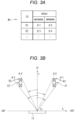
- FIGs. 3A and 3B are explanatory diagrams illustrating an example of the map information M1.
- the map information M1 is stored as table format information including an identification number ID of the target region R and an angle indicating a direction in which the target region R is present.
- the relative position between the sound collecting device 11 and the target region R is uniquely determined in the map information M1. Therefore, a user inputs, to the input device 16, position information of the target region R with respect to the sound collecting device 11 to store the position information in the map information database 141.
- the map information M1 may be acquired by receiving the map information M1 from a management device via the communication device 17.
- FIG. 3B is a schematic diagram illustrating an example of the map information M1 on a predetermined XY plane.
- the XY plane is a plane perpendicular to a plane (hereinafter referred to as an array surface) on which the plurality of microphones 110 of the sound collecting device 11 are arranged.
- FIG. 3B illustrates the positions of the plurality of target regions R projected on the predetermined XY plane in a case where the plurality of target regions R are viewed, from the sound collecting device 11, in a direction parallel to the array surface.
- FIG. 3B illustrates the positions of the plurality of target regions R projected on the predetermined XY plane in a case where the plurality of target regions R are viewed, from the sound collecting device 11, in a direction parallel to the array surface.
- an angle in a positive direction of the Y-axis is set to 0° on the XY plane in which a center of the array surface of the sound collecting device 11 is set as an origin O, and the minimum angle and the maximum angle of the range, in which a contour of the target region R is present as viewed from the origin O, are stored in the map information M1.
- an angle ⁇ 1 illustrated in FIG. 3B is the maximum angle ⁇ 1 of the target region R1
- an angle ⁇ 2 is the minimum angle ⁇ 2 of the target region R1. That is, a range in which the angle is ⁇ 2 or more and ⁇ 1 or less as viewed from the origin O is a range in which the target region R1 is present.
- an angle ⁇ 3 illustrated in FIG. 3B is the maximum angle ⁇ 3 of the target region R2
- an angle ⁇ 4 is the minimum angle ⁇ 4 of the target region R2. That is, the range in which the angle is ⁇ 4 or more and ⁇ 3 or less as viewed from the origin O is a range in which the target region R2 is present.
- only an angle of a straight line passing through the origin O and the center of the target region R may be stored in the map information M1.
- the map information M1 may further include information on an angle in a direction orthogonal to the XY plane. That is, the Z direction orthogonal to the XY plane is defined, and in an XYZ coordinate system, in a case where the plurality of target regions R are viewed, from the sound collecting device 11, in the direction parallel to the array surface, the minimum angle and the maximum angle viewed from the origin O of the range in which the contour of the target region R is present may be added to the information stored in the map information M1, for the plurality of target regions R projected on a predetermined YZ plane.
- the sound pressure signal storage unit 142 illustrated in FIG. 1 is configured to store the primary sound pressure signal SP1 acquired by the sound collecting device 11 and a secondary sound pressure signal SP2 calculated by the calculation device 13.
- the calculation device 13 is a device configured to read the computer program 143 from the storage device 14 and configured to perform various calculations, and is, for example, a central processing unit (CPU).
- the calculation device 13 realizes a function as the generation unit 131 and a function as the detection unit 132 by executing the computer program 143 stored in the storage device 14.
- the generation unit 131 is configured to perform the beamforming processing on the primary sound pressure signal SP1 to generate the secondary sound pressure signal SP2 from the primary sound pressure signal SP1.
- the detection unit 132 is configured to detect an abnormality in the target region R, based on the primary sound pressure signal SP1 or the secondary sound pressure signal SP2. Specific functions of the generation unit 131 and the detection unit 132 will be described later.
- the display device 15 is electrically connected to the information processing device 12, and is configured to display the monitoring information of the target region R to the user.
- the display device 15 is, for example, a display and a speaker.
- the monitoring information includes, for example, information on an abnormality detection result and an abnormality cause detected by the detection unit 132.
- the input device 16 is electrically connected to the information processing device 12, and is configured to transmit, to the information processing device 12, information input from the user.
- the input device 16 is, for example, a mouse and a keyboard.
- the communication device 17 is electrically connected to the information processing device 12, and is configured to transmit and receive various information to and from an external device (for example, the management device configured to manage the plurality of monitoring devices 1), which is not illustrated.
- the communication device 17 is configured to transmit, to the management device, the monitoring information of the target region R, and configured to receive, from the management device, various types of setting information such as the map information M1.
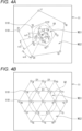
- FIG. 4A is an explanatory diagram illustrating the arrangement of the plurality of microphones 110 in the sound collecting device 11.
- 21 microphones 110 are arranged on the array surface of the sound collecting device 11.
- the microphones 110 of a first round that is, numbers 2 to 6
- the microphones 110 of a second round that is, numbers 7 to 11
- the microphones 110 of a second round that is, numbers 7 to 11
- the microphones 110 of a third round that is, numbers 12 to 16
- the microphones 110 of a fourth round that is, numbers 17 to 21
- the microphones 110 of a fourth round that is, numbers 17 to 21
- a phase, in a rotation direction around the microphone 110 of the number 1, of the regular pentagon of the second round is different from a phase of the regular pentagon of the first round by an angle ⁇ 1 in a counterclockwise direction in FIG. 4A .
- a phase, in the rotation direction around the microphone 110 of the number 1, of the regular pentagon of the third round is different from the phase of the regular pentagon of the second round by an angle ⁇ 2 in the counterclockwise direction in FIG. 4A .
- the angle ⁇ 2 is larger than the angle ⁇ 1 ( ⁇ 2 > ⁇ 1).
- a phase, in the rotation direction around the microphone 110 of the number 1, of the regular pentagon of the fourth round is different from the phase of the regular pentagon of the third round by an angle ⁇ 3 in the counterclockwise direction in FIG. 4A .
- the angle ⁇ 3 is larger than the angle ⁇ 2 ( ⁇ 3 > ⁇ 2).
- the microphones 110 arranged on the array surface of the sound collecting device 11 can be arranged to be more dispersed as compared with a case where the microphones 110 of the first to fourth rounds are arranged without providing a phase difference in the peripheral direction.
- the angle is expressed as ⁇ 3 > ⁇ 2 > ⁇ 1
- intervals between the microphones 110 in the peripheral direction and a radial direction are larger as the microphones 110 are positioned more outward.
- the intervals between the microphones 110 in the peripheral direction and the radial direction are smaller as the microphones 110 are positioned more inward.
- the microphones 110 that is, the numbers 1 to 11 that are arranged in the center, the first round, and the second round and arranged on an inner side of a circle Q1 as illustrated in FIG. 4A configure a first microphone group MG1 in which the interval between the microphones 110 is a distance suitable for the detection of the ultrasonic wave.
- the microphones 110 that is, the numbers 12 to 21 that are arranged on the third and fourth rounds and arranged on an outer side of the circle Q1 configure a second microphone group MG2 in which the interval between the microphones 110 is a distance suitable for the detection of the audible sound.
- the interval between the microphones 110 in the first microphone group MG1 is about 2.3 mm to 8.5 mm.
- a wavelength of the ultrasonic waves is, for example, about 17 mm at 20 kHz and about 7 mm at 50 kHz. Therefore, according to the sound wave detected in the first microphone group MG1, a sufficient phase difference can be obtained for the detection of the target region R including the abnormal portion P.
- the interval between the microphones 110 in the second microphone group MG2 is 8.5 mm or more. Therefore, each microphone 110 of the second microphone group MG2 is suitable for detecting audible sound having a longer wavelength than the ultrasonic waves, and is configured to detect a wide range of sound waves as compared with the first microphone group MG1.
- the sound collecting device 11 is configured to output, as the primary sound pressure signal SP1, a detection result of the ultrasonic wave by the first microphone group MG1 and a detection result of the audible sound by the second microphone group MG2.
- the sound collecting device 11 can accurately detect the audible sound suitable for the presence or absence of an abnormality in the device 2 and the detection of an abnormal content, and can accurately detect the ultrasonic wave suitable for the detection of the abnormal portion.
- the arrangement of the plurality of microphones 110 in the sound collecting device 11 is not limited to the arrangement illustrated in FIG. 4A , and may be, for example, a hexagonal arrangement as illustrated in FIG. 4B .
- the centers of the microphones 110 of the number 2 to 7 are positioned on vertexes of a regular hexagon in which a length of one side is D1, and the center of the microphone 110 of the number 1 is positioned at a center of gravity of the regular hexagon.
- the centers of the microphones 110 of the numbers 8 to 19 are positioned on the respective vertexes and middle points of the respective sides of the regular hexagon that surrounds the regular hexagon and whose one side is twice as long as D1.
- the plurality of microphones 110 positioned at the outermost periphery are positioned on the sides or the vertexes of the regular hexagon.
- the microphones 110 of the numbers 1 to 7 arranged on an inner side of a circle Q2 illustrated in FIG. 4B configure the first microphone group MG1 in which the interval between the microphones 110 is set to a distance suitable for the detection of the ultrasonic wave
- the microphones 110 of the numbers 8 to 19 arranged on an outer side of the circle Q2 configure the second microphone group MG2 in which the interval between the microphones 110 is set to a distance suitable for the detection of the audible sound.
- the sound collecting device 11 of the present embodiment is the sound collecting device 11 used in the monitoring device 1 configured to monitor the operation state of the device 2, and includes the plurality of microphones 110 configured to convert, into the sound pressure signal, the sound wave including the audible sound and the ultrasonic wave emitted from the device 2.
- the plurality of microphones 110 include the first microphone group MG1 in which the interval between the microphones 110 is set to a distance suitable for the detection of the ultrasonic wave, and the second microphone group MG2 in which the interval between the microphones 110 is set to a distance suitable for the detection of the audible sound and larger than the distance in the first microphone group MG1.
- the sound collecting device 11 can be easily arranged in the housing of the device 2 or in the immediate vicinity of the portion of the device 2 to be monitored.
- FIG. 5 is a flowchart illustrating a procedure of a monitoring processing according to the embodiment.
- the monitoring device 1 gives an instruction, to the monitoring device 1, to perform the monitoring processing, using the input device 16, the monitoring device 1 starts the monitoring processing.
- the monitoring device 1 periodically performs the following monitoring processing until the device 2 is stopped or until the user gives an instruction, to the monitoring device 1, to stop the monitoring processing, using the input device 16.
- a sound collecting step S1 is performed.
- the sound collecting step S1 is performed while the device 2 illustrated in FIG. 2 is operating. That is, during the sound collecting step S1, the plurality of respective target regions R1 and R2 generate the sound waves SW1, and the sound collecting device 11 propagates the synthesized sound wave SW2 in which sound waves SW1 are synthesized (see FIG. 2 ).
- the plurality of microphones 110 included in the sound collecting device 11 is configured to convert the input synthesized sound wave SW2 into the primary sound pressure signal SP1 and output the primary sound pressure signal SP1 to the information processing device 12.
- the microphone 110 is configured to convert, into the primary sound pressure signal SP1, the synthesized sound wave SW2 of the audible sound (that is, 20 Hz or more and less than 20 kHz) and the ultrasonic wave (that is, 20 kHz or more).
- the plurality of primary sound pressure signals SP1 acquired for each microphone 110 are stored in the sound pressure signal storage unit 142. Accordingly, the sound collecting step S1 ends.
- the information processing device 12 is configured to acquire the primary sound pressure signal SP1 detected in the sound collecting step S1 at an initial stage of an operation in which there is no abnormality in the device 2, as an initial primary sound pressure signal SP0 in distinction from the other primary sound pressure signal SP1. Then, the information processing device 12 is configured to store the initial primary sound pressure signal SP0 in the sound pressure signal storage unit 142.
- an abnormality detection step S2 is performed.
- the detection unit 132 is configured to detect the presence or absence of an abnormality in the target region R, using, in particular, a signal in a frequency range of an audible sound (that is, 20 Hz or more and less than 20 kHz) in the primary sound pressure signal SP1 stored in the sound pressure signal storage unit 142.
- a characteristic sound wave (hereinafter, referred to as a characteristic sound wave SW3) in the order of several hundred kHz (that is, an audible range) is generated from the target region R in which the abnormality occurs.
- the detection unit 132 is configured to detect the presence or absence of the characteristic sound wave SW3 from the signal particularly in the frequency range of the audible sound (that is, 20 Hz or more and less than 20 kHz) of the primary sound pressure signal SP1.
- the characteristic sound wave SW3 may be emitted from the target region R in which there is no abnormality. That is, it is difficult to detect the target region R including the abnormal portion P based on the characteristic sound wave SW3.
- the sound collecting device 11 can detect the synthesized sound wave SW2 in which the sound waves SW1 from the range including the plurality of target regions R are collected. Therefore, in a case where an abnormality occurs in one of the target regions R and the characteristic sound wave SW3 is generated, the sound collecting device 11 can reliably detect the synthesized sound wave SW2 including the sound wave SW1 and the characteristic sound wave SW3.
- the detection unit 132 is configured to attempt to detect the characteristic sound wave SW3 in the audible range using the primary sound pressure signal SP1 stored in the sound pressure signal storage unit 142. In a case where the detection unit 132 detects the characteristic sound wave SW3, the detection unit 132 is configured to output a result of "abnormality" to the storage device 14. In a case where the detection unit 132 does not detect the characteristic sound wave SW3, the detection unit 132 is configured to output a result of "no abnormality" to the storage device 14. In the abnormality detection step S2, the detection of the target region R in which the abnormality occurs is not performed. The detection of the target region R in which the abnormality occurs is performed in a subsequent abnormal portion detection step S4.
- the detection unit 132 can accurately detect the presence or absence of an abnormality in the device 2 by detecting a typical sound wave emitted from the abnormal device 2 from a signal, in an audible range, of the primary sound pressure signal SP1. In this case, since it is not necessary for the detection unit 132 to determine the presence or absence of an abnormality for each of the plurality of target regions R, the detection unit 132 can detect the presence or absence of an abnormality in the device 2 with a small amount of calculation.
- the information processing device 12 performs determination based on the detection result of the detection unit 132.
- the detection unit 132 outputs the result of the "abnormality" in the abnormality detection step S2 (that is, in the case of "YES")
- the processing then proceeds to the abnormal portion detection step S4.
- the processing proceeds to a notification step S6.
- the information processing device 12 detects that there is an abnormality in the device 2 in the abnormality detection step S2
- the information processing device 12 is configured to perform the abnormal portion detection step S4.
- the amount of calculation of the information processing device 12 can be reduced.
- calculation time of the information processing device 12 is shortened, and the presence or absence of abnormality of the device 2 can be determined in real time.
- the abnormal portion detection step S4 is performed.
- the detection unit 132 is configured to perform a processing of detecting the target region R including the abnormal portion P, by using the secondary sound pressure signal SP2 stored in the sound pressure signal storage unit 142.
- the secondary sound pressure signal SP2 is generated by performing the beamforming processing on the primary sound pressure signal SP1.
- a beam scanning range is set within a detection range, of an angle with respect to an origin O of the sound collecting device 11, of the synthesized sound wave SW2 .
- the beam scanning range is scanned for each beam scanning range of about 0.5° to 1° to process the primary sound pressure signal SP1.
- a power spectral density hereinafter referred to as power spectral density (PSD)
- PSD power spectral density
- a known method for example, delay and sum beamforming or filter and sum beamforming
- the interval between the microphones 110 is about 2.3 mm to 8.5 mm, which is smaller than half the wavelength of the ultrasonic wave. For this reason, in a case where the signal, in the ultrasonic range, of the primary sound pressure signal SP1, detected in the first microphone group MG1 is used, a phase difference, of the signal detected by each microphone 110, of one wavelength or more can be reliably obtained. In a case where the primary sound pressure signal SP1 is used, good localization accuracy can be obtained in the secondary sound pressure signal SP2 after the beamforming processing. Accordingly, the monitoring device 1 can accurately detect the target region R based on the secondary sound pressure signal SP2.
- the center of the sound collecting device 11 is defined as the origin O, and an angle of a front direction of the sound collecting device 11 from the origin O is defined as 0°.
- a scanning angle of the beam with respect to the angle of 0° is referred to as a beam scanning angle, and the "beam scanning range” is set to a range from -35° to +35°.
- the detection unit 132 is configured to detect the target region R including the abnormal portion P, by using the secondary sound pressure signal SP2 of the ultrasonic range (that is, 20 kHz or more).
- the deterioration of a lubrication state of a rotation portion, which causes scratches on the rotation portion (for example, the bearing) of the device 2 is likely to appear as a sound wave of about 30 kHz to 35 kHz. Therefore, the sound wave of the ultrasonic range (that is, 20 kHz or more) is suitable for detection of the target region R including the abnormal portion P of the rotation portion.
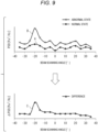
- FIG. 8 illustrates the secondary sound pressure signal SP2 generated from the device 2 having no abnormality.
- the secondary sound pressure signal SP2 can be generated based on the initial primary sound pressure signal SP0.
- the secondary sound pressure signal SP2 generated by performing the beamforming processing on the initial primary sound pressure signal SP0 is distinguished and is referred to as an initial secondary sound pressure signal SP3.
- FIG. 8 illustrates the initial secondary sound pressure signal SP3 in the ultrasonic range, and power spectra independent of the beam scanning angle (hereinafter, referred to as power spectrum (PS)) appear in the vicinity of 30 kHz, 36 kHz, 42 kHz, and 48 kHz.
- PS power spectrum
- the PS of the natural vibration frequency becomes noise in a case where the target region R including the abnormal portion P is detected. Therefore, in a case where the detection unit 132 detects the target region R, it is preferable to use the secondary sound pressure signal SP2 in a frequency band in which the natural vibration frequency of the device 2 is avoided.
- the secondary sound pressure signal SP2 in the frequency band from 43 kHz to 47 kHz, corresponding to the range surrounded by a dotted line illustrated in FIG. 8 is used to detect the target region R including the abnormal portion P.
- the PSD can be illustrated on a graph by changing shade and a color tone according to the density of PS in a graph of PS as indicated by lines or points in FIG. 8 .
- the information processing device 12 of the present embodiment is configured to detect the abnormal portion P of the device 2, based on the secondary sound pressure signal SP2 in the frequency band that does not include the natural vibration frequency of the device 2, in the processing of the abnormal portion detection step S4. With this configuration, it is possible to more accurately detect the abnormal portion P of the device 2.
- FIG. 9 illustrates a relationship between the beam scanning angle and the PSD of the secondary sound pressure signal SP2 of a frequency (for example, 46 kHz) selected from the frequency band (see FIG. 8 ) suitable for detection of the target region R including the abnormal portion P.
- FIG. 9 illustrates a graph A related to the device 2 in which the operation state is normal and a graph B related to the device 2 in which the operation state is abnormal.
- the graph A is a graph based on the initial secondary sound pressure signal SP3.
- the monitoring device 1 is configured to detect the abnormal portion P, based on the difference between the initial secondary sound pressure signal SP3 (that is, the graph A) of the device 2 having no abnormality in the operation state and the secondary sound pressure signal SP2 (that is, the graph B) of the device 2 having an abnormality.
- the difference that is, the graph C
- the initial secondary sound pressure signal SP3 that is, the graph A
- the secondary sound pressure signal SP2 that is, the graph B
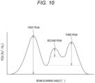
- the detection unit 132 is configured to determine that an angle of a portion having the largest peak value of the difference (that is, the first peak) is an angle at which the target region R including the abnormal portion P is present.
- the detection unit 132 is configured to collate, with the map information M1, the angle, at which the target region R including the abnormal portion P is present, determined from the secondary sound pressure signal SP2 (that is, the angle of -20° in the present embodiment) to detect the target region R in which the abnormality occurs. Accordingly, the abnormal portion detection step S4 ends.
- the detection unit 132 is configured to detect an angle of each sound wave SW1, as the propagation direction, from the synthesized sound wave SW2 detected by the sound collecting device 11, and configured to collate the angle with the map information M1, to detect the target region R including the abnormal portion P.
- the information processing device 12 of the present embodiment is configured to perform the processing of acquiring the initial primary sound pressure signal SP0 of the sound wave emitted from the device 2 at an initial stage of the operation in the sound collecting step S1, and in the processing of performing the abnormal portion detection step S4, the information processing device 12 is configured to detect the abnormal portion P of the device 2 based on the difference between the initial secondary sound pressure signal SP3 generated by performing the beamforming processing on the initial primary sound pressure signal SP0 and the secondary sound pressure signal SP2 after the initial stage of the operation of the device 2. With this configuration, it is possible to more accurately detect the abnormal portion P of the device 2.
- an abnormal content detection step S5 is performed.
- the detection unit 132 is configured to perform a processing of detecting a content of the abnormality.
- the detection unit 132 is configured to detect the content of the abnormality occurring in the target region R, using, in particular, a signal in a frequency range of an audible sound (that is, 20 Hz or more and less than 20 kHz) in the primary sound pressure signal SP1 stored in the sound pressure signal storage unit 142.
- the detection unit 132 is configured to acquire a feature amount included in the signal, in the audible range, of the primary sound pressure signal SP1. For example, a feature amount in the target region R is compared with a plurality of pieces of abnormality information stored in a predetermined database.
- the characteristic sound wave SW3 in the audible range of about several hundred Hz used in the abnormality detection step S2 can be used as the feature amount.
- the abnormality information matching the feature amount (that is, the characteristic sound wave SW3) among the plurality of pieces of abnormality information it is determined that the abnormality of the target region R is an abnormality based on the abnormality information.
- the abnormality is an unknown abnormality. Accordingly, the abnormal content detection step S5 ends.
- the information processing device 12 of the present embodiment is configured to detect that there is an abnormality in the device 2 in the abnormality detection step S2, the information processing device 12 can further perform the processing of the abnormal content detection step S5 of detecting the abnormal content of the device 2 based on the signal, in the audible range, of the primary sound pressure signal SP1.
- the sound wave for which the abnormal content is detected as the audible sound (that is, the characteristic sound wave SW3 in the present embodiment)
- the abnormal content detection step S5 can be performed after the determination result of "abnormality" in the device 2 is output in the abnormality detection step S2. That is, the abnormal content detection step S5 may be performed before the abnormal portion detection step S4 or may be performed in parallel with the abnormal portion detection step S4.
- the notification step S6 is performed.
- the information processing device 12 is configured to output the monitoring information to the display device 15 based on the abnormality determination result, the detection result of the abnormal target region R, and a detection result of the abnormal content stored in the sound pressure signal storage unit 142. In this case, it is preferable to output the monitoring information for each of the plurality of target regions R.
- the information processing device 12 may be configured to output the monitoring information to the management device via the communication device 17. In a case where it is determined that there is an abnormality in the target region R, a warning sound may be issued from the speaker of the display device 15. Accordingly, the notification step S6 ends.
- a first pattern PT1 is a case where the bearing 22 having the abnormal portion P in a rolling element is used.
- a second pattern PT2 is a case where the bearing 22 having the abnormal portion P in an inner ring is used.
- a third pattern PT3 is a case where the bearing 21 having the abnormal portion P in a rolling element is used.
- a fourth pattern PT4 is a case where the bearing 21 having the abnormal portion P in an inner ring is used.
- a fifth pattern PT5 is a case where the bearing 21 having the abnormal portion P in the inner ring and the bearing 22 having the abnormal portion P in the rolling element are used.
- FIG. 11A illustrates detection results of the difference of the PSD in the case of the first pattern PT1 and the second pattern PT2.
- the peak of the PSD appears in the vicinity of the angle of -22°.
- the angle of -22° is included in a range of -16° to -31° that is an existence range of the target region R2 (that is, the bearing 22) stored in the map information M1. Then, based on the detection result, the detection unit 132 determines that there is the abnormal portion P in the target region R2 in which the bearing 22 is present.
- FIG. 11B illustrates detection results of the difference of the PSD in the case of the third pattern PT3 and the fourth pattern PT4.
- the peak of the PSD appears in the vicinity of the angle of +22°.
- the angle of +22° is included in a range of +16° to +31° that is an existence range of the target region R1 (that is, the bearing 21) stored in the map information M1. Then, based on the detection result, the detection unit 132 determines that there is the abnormal portion P in the target region R1 in which the bearing 21 is present.
- FIG. 11C illustrates a detection result of the difference of the PSD in the case of the fifth pattern PT5.
- the peak of the PSD appears in the vicinity of the angle of -22° and in the vicinity of the angle of +22°.
- the angle of +22° is included in the range of +16° to +31° that is the existence range of the bearing 21 stored in the map information M1, and the angle of -22° is included in the range of -16° to -31° that is the existence range of the bearing 22.
- the detection unit 132 of the monitoring device 1 determined that there is the abnormal portion P in each of the target region R1 in which the bearing 21 is present and the target region R2 in which the bearing 22 is present, based on the experimental result.
- the monitoring device 1 of the present embodiment is the monitoring device 1 configured to monitor the operation state of the device 2, and the monitoring device 1 includes the sound collecting device 11 in which the plurality of microphones 110 configured to convert the sound wave including the audible sound and the ultrasonic wave emitted from the device 2 into the primary sound pressure signal SP1 are arranged, and the information processing device 12 configured to perform processing of performing the abnormality detection step S2 of detecting the presence or absence of the abnormality of the device 2 based on the signal, in the audible range, of the primary sound pressure signal SP1, and a processing of generating the secondary sound pressure signal SP2 by performing the beamforming processing on the signal, in the ultrasonic range, of the primary sound pressure signal SP1 and performing the abnormal portion detection step S4 of detecting the target region R including the abnormal portion P of the device 2 based on the secondary sound pressure signal SP2.
- the monitoring device 1 it is possible to accurately detect the target region R including the abnormal portion P without increasing the interval between the microphones 110 by setting, to the ultrasonic wave, the sound wave for detecting the target region R including the abnormal portion P of the device 2. Further, by setting, to the audible sound, the sound wave for detecting the abnormality of the device 2, it is possible to accurately detect the abnormality of the device 2 based on the typical audible sound emitted from the device 2 having the abnormality. As a result, it is possible to accurately detect the abnormality of the device without increasing the size of the sound collecting device 11.
- the embodiments disclosed above are illustrative and non-restrictive in every respect. That is, the monitoring device of the present disclosure is not limited to the illustrated embodiment, and may be another form within the scope of the present disclosure.
Landscapes
- Physics & Mathematics (AREA)
- General Physics & Mathematics (AREA)
- Acoustics & Sound (AREA)
- Health & Medical Sciences (AREA)
- Otolaryngology (AREA)
- Engineering & Computer Science (AREA)
- Signal Processing (AREA)
- General Health & Medical Sciences (AREA)
- Measurement Of Mechanical Vibrations Or Ultrasonic Waves (AREA)
- Testing Of Devices, Machine Parts, Or Other Structures Thereof (AREA)
Applications Claiming Priority (2)
| Application Number | Priority Date | Filing Date | Title |
|---|---|---|---|
| JP2020192520A JP7559521B2 (ja) | 2020-11-19 | 2020-11-19 | 監視装置、集音装置及び監視方法 |
| PCT/JP2021/037928 WO2022107507A1 (ja) | 2020-11-19 | 2021-10-13 | 監視装置、集音装置及び監視方法 |
Publications (2)
| Publication Number | Publication Date |
|---|---|
| EP4249865A1 true EP4249865A1 (de) | 2023-09-27 |
| EP4249865A4 EP4249865A4 (de) | 2024-10-02 |
Family
ID=81708954
Family Applications (1)
| Application Number | Title | Priority Date | Filing Date |
|---|---|---|---|
| EP21894381.9A Withdrawn EP4249865A4 (de) | 2020-11-19 | 2021-10-13 | Überwachungsvorrichtung, tonerfassungsvorrichtung und überwachungsverfahren |
Country Status (5)
| Country | Link |
|---|---|
| US (1) | US20230408328A1 (de) |
| EP (1) | EP4249865A4 (de) |
| JP (1) | JP7559521B2 (de) |
| CN (1) | CN116529569A (de) |
| WO (1) | WO2022107507A1 (de) |
Cited By (2)
| Publication number | Priority date | Publication date | Assignee | Title |
|---|---|---|---|---|
| CN117232643A (zh) * | 2023-11-10 | 2023-12-15 | 万帮数字能源股份有限公司 | 充电桩的声功率级测试方法及装置 |
| EP4567549A1 (de) * | 2023-12-05 | 2025-06-11 | Yokogawa Electric Corporation | Detektionsvorrichtung, zeitsynchronisationsverfahren, nichttransitorisches computerlesbares aufzeichnungsmedium und detektionssystem |
Families Citing this family (2)
| Publication number | Priority date | Publication date | Assignee | Title |
|---|---|---|---|---|
| WO2026083670A1 (ja) * | 2024-10-18 | 2026-04-23 | Jfeスチール株式会社 | 音響診断装置及び音響診断方法 |
| JP7827233B1 (ja) * | 2024-10-18 | 2026-03-10 | Jfeスチール株式会社 | 音響診断装置及び音響診断方法 |
Family Cites Families (29)
| Publication number | Priority date | Publication date | Assignee | Title |
|---|---|---|---|---|
| JPH1151300A (ja) * | 1997-07-30 | 1999-02-26 | Toshiba Corp | リーク監視装置 |
| JP4401501B2 (ja) * | 1999-11-29 | 2010-01-20 | 東北電力株式会社 | ベルトコンベヤ異常診断装置 |
| JP2003156387A (ja) * | 2001-11-22 | 2003-05-30 | Matsushita Electric Ind Co Ltd | 異常音検出装置および異常音検出方法 |
| JP2006105727A (ja) * | 2004-10-04 | 2006-04-20 | Nsk Ltd | 機械装置の異常感知ユニット |
| JP2008268187A (ja) * | 2007-03-26 | 2008-11-06 | Nippon Steel Corp | 極低速回転機械の異常診断方法及び装置 |
| JP2010197124A (ja) * | 2009-02-24 | 2010-09-09 | Tokyo Electric Power Co Inc:The | 異音検出装置、方法及びプログラム |
| JP5189536B2 (ja) * | 2009-03-26 | 2013-04-24 | 池上通信機株式会社 | 監視装置 |
| JP2011191181A (ja) * | 2010-03-15 | 2011-09-29 | Toshiba Industrial Products Manufacturing Corp | 回転機器の異常診断システム、回転機器の異常診断装置及び回転機器の異常診断方法 |
| KR101715779B1 (ko) * | 2010-11-09 | 2017-03-13 | 삼성전자주식회사 | 음원 신호 처리 장치 및 그 방법 |
| JP2012202958A (ja) * | 2011-03-28 | 2012-10-22 | Ono Sokki Co Ltd | 騒音源同定システム |
| JP5642027B2 (ja) * | 2011-07-06 | 2014-12-17 | 株式会社日立パワーソリューションズ | 異音診断装置および異音診断方法 |
| KR101126777B1 (ko) * | 2011-09-29 | 2012-03-29 | 한국철도기술연구원 | 음원 특성 규명을 위한 마이크로폰 어레이 |
| JP5930789B2 (ja) | 2012-03-23 | 2016-06-08 | 三菱電機株式会社 | 異常音診断装置 |
| JP6061693B2 (ja) * | 2013-01-18 | 2017-01-18 | 株式会社日立パワーソリューションズ | 異常診断装置およびこれを用いた異常診断方法 |
| JP6223935B2 (ja) * | 2014-09-12 | 2017-11-01 | 株式会社神戸製鋼所 | 回転機械異常検出装置および該方法ならびに回転機 |
| KR101522996B1 (ko) * | 2015-01-30 | 2015-05-27 | (주)코어센스 | 비파괴 검사용 복합 영상 출력장치 |
| JP2017032488A (ja) | 2015-08-05 | 2017-02-09 | 株式会社リコー | 情報処理装置、診断方法、およびプログラム |
| US9800973B1 (en) * | 2016-05-10 | 2017-10-24 | X Development Llc | Sound source estimation based on simulated sound sensor array responses |
| JP6781612B2 (ja) * | 2016-12-02 | 2020-11-04 | 大成建設株式会社 | シールドマシンの劣化診断方法 |
| JP2018179626A (ja) * | 2017-04-07 | 2018-11-15 | 新日本無線株式会社 | 超音波受信器 |
| JP7011533B2 (ja) * | 2018-05-22 | 2022-01-26 | Jfeスチール株式会社 | 部分放電音源の表示方法および部分放電音源の表示装置 |
| WO2020162426A1 (ja) * | 2019-02-05 | 2020-08-13 | 日本電気株式会社 | 解析装置、解析方法、およびプログラム、ならびに、センサの構造 |
| JP2020192520A (ja) | 2019-05-21 | 2020-12-03 | フロイント産業株式会社 | 連続コーティング装置 |
| CN110672313B (zh) * | 2019-10-22 | 2021-06-01 | 上海声茵科技有限公司 | 一种基于声音信号的故障诊断方法及其设备 |
| US11688413B2 (en) * | 2019-12-19 | 2023-06-27 | Taiwan Semiconductor Manufacturing Co., Ltd. | Method and system for audio recognition of arcing during semiconductor process |
| JP2021143869A (ja) * | 2020-03-10 | 2021-09-24 | 株式会社ジェイテクト | 監視装置及び監視方法 |
| CN111580050A (zh) * | 2020-05-28 | 2020-08-25 | 国网上海市电力公司 | 一种用于识别gis设备异响声源位置的装置及方法 |
| JP2022032077A (ja) * | 2020-08-11 | 2022-02-25 | 株式会社ジェイテクト | 監視装置、集音装置及び監視方法 |
| US12072413B1 (en) * | 2021-03-31 | 2024-08-27 | Amazon Technologies, Inc. | Method for wall detection and localization |
-
2020
- 2020-11-19 JP JP2020192520A patent/JP7559521B2/ja active Active
-
2021
- 2021-10-13 EP EP21894381.9A patent/EP4249865A4/de not_active Withdrawn
- 2021-10-13 WO PCT/JP2021/037928 patent/WO2022107507A1/ja not_active Ceased
- 2021-10-13 US US18/036,717 patent/US20230408328A1/en not_active Abandoned
- 2021-10-13 CN CN202180077776.1A patent/CN116529569A/zh active Pending
Cited By (3)
| Publication number | Priority date | Publication date | Assignee | Title |
|---|---|---|---|---|
| CN117232643A (zh) * | 2023-11-10 | 2023-12-15 | 万帮数字能源股份有限公司 | 充电桩的声功率级测试方法及装置 |
| CN117232643B (zh) * | 2023-11-10 | 2024-03-22 | 万帮数字能源股份有限公司 | 充电桩的声功率级测试方法及装置 |
| EP4567549A1 (de) * | 2023-12-05 | 2025-06-11 | Yokogawa Electric Corporation | Detektionsvorrichtung, zeitsynchronisationsverfahren, nichttransitorisches computerlesbares aufzeichnungsmedium und detektionssystem |
Also Published As
| Publication number | Publication date |
|---|---|
| JP2022081152A (ja) | 2022-05-31 |
| US20230408328A1 (en) | 2023-12-21 |
| EP4249865A4 (de) | 2024-10-02 |
| JP7559521B2 (ja) | 2024-10-02 |
| WO2022107507A1 (ja) | 2022-05-27 |
| CN116529569A (zh) | 2023-08-01 |
Similar Documents
| Publication | Publication Date | Title |
|---|---|---|
| EP4249865A1 (de) | Überwachungsvorrichtung, tonerfassungsvorrichtung und überwachungsverfahren | |
| US20170205316A1 (en) | Rotary machine abnormality detection device and method thereof and rotary machine | |
| US10247599B2 (en) | Rotating machine abnormality detection device and method and rotating machine | |
| US8831233B2 (en) | Monitoring apparatus and method | |
| KR20090094171A (ko) | 극저속 회전 기계의 이상 진단 방법 및 장치 | |
| US10288475B2 (en) | Rotating machine abnormality detection device, rotating machine abnormality detection method, and rotating machine | |
| JP7077426B2 (ja) | 診断装置及びこれを備えた設備並びに診断方法 | |
| JP7228497B2 (ja) | 信号処理装置、信号処理方法およびプログラム | |
| JP2014137323A (ja) | 異常診断装置およびこれを用いた異常診断方法 | |
| TW202045899A (zh) | 解析裝置、解析方法及程式、以及感測器之構造 | |
| CN114242085A (zh) | 旋转设备的故障诊断方法、装置 | |
| JP2008249702A (ja) | 音響測定装置及び音響測定方法 | |
| JP2005300517A (ja) | ころがり軸受の異常診断方法および装置 | |
| Aizawa et al. | An acoustic-array based structural health monitoring technique for wind turbine blades | |
| EP3954975A1 (de) | Überwachungsvorrichtung, geräuscherfassungsvorrichtung und überwachungsverfahren | |
| US20210289303A1 (en) | Monitoring apparatus and monitoring method | |
| JP2011191166A (ja) | 音響診断方法、プログラム及び装置 | |
| CN117053919A (zh) | 基于传声器阵列的永磁电机噪声成分可视化方法和系统 | |
| JP4209793B2 (ja) | 音響信号に基づく異常診断方法及び該方法を実行するために用いるプログラム | |
| JP2001296258A (ja) | 結晶方位測定方法 | |
| CN119469005B (zh) | 定子组装检测方法、装置、设备及存储介质 | |
| CN115184868B (zh) | 一种定位噪声源三维位置的方法 | |
| CN120369611B (zh) | 一种基于等效模态振型导数的结构损伤识别方法 | |
| JPH04316198A (ja) | プラント異常検出装置 | |
| Barański | Noise source analysis of the nitrogen generation system |
Legal Events
| Date | Code | Title | Description |
|---|---|---|---|
| STAA | Information on the status of an ep patent application or granted ep patent |
Free format text: STATUS: THE INTERNATIONAL PUBLICATION HAS BEEN MADE |
|
| PUAI | Public reference made under article 153(3) epc to a published international application that has entered the european phase |
Free format text: ORIGINAL CODE: 0009012 |
|
| STAA | Information on the status of an ep patent application or granted ep patent |
Free format text: STATUS: REQUEST FOR EXAMINATION WAS MADE |
|
| 17P | Request for examination filed |
Effective date: 20230516 |
|
| AK | Designated contracting states |
Kind code of ref document: A1 Designated state(s): AL AT BE BG CH CY CZ DE DK EE ES FI FR GB GR HR HU IE IS IT LI LT LU LV MC MK MT NL NO PL PT RO RS SE SI SK SM TR |
|
| DAV | Request for validation of the european patent (deleted) | ||
| DAX | Request for extension of the european patent (deleted) | ||
| A4 | Supplementary search report drawn up and despatched |
Effective date: 20240902 |
|
| RIC1 | Information provided on ipc code assigned before grant |
Ipc: G01M 13/045 20190101ALI20240827BHEP Ipc: G01M 7/02 20060101ALI20240827BHEP Ipc: G01H 3/12 20060101ALI20240827BHEP Ipc: G01H 3/06 20060101ALI20240827BHEP Ipc: G01H 3/00 20060101ALI20240827BHEP Ipc: G01M 99/00 20110101ALI20240827BHEP Ipc: G01H 17/00 20060101AFI20240827BHEP |
|
| STAA | Information on the status of an ep patent application or granted ep patent |
Free format text: STATUS: THE APPLICATION HAS BEEN WITHDRAWN |
|
| 18W | Application withdrawn |
Effective date: 20250610 |