EP4251063B1 - Sonde ultrasonore à capacité de suivi de cible - Google Patents
Sonde ultrasonore à capacité de suivi de cible Download PDFInfo
- Publication number
- EP4251063B1 EP4251063B1 EP21835043.7A EP21835043A EP4251063B1 EP 4251063 B1 EP4251063 B1 EP 4251063B1 EP 21835043 A EP21835043 A EP 21835043A EP 4251063 B1 EP4251063 B1 EP 4251063B1
- Authority
- EP
- European Patent Office
- Prior art keywords
- ultrasound
- targets
- ultrasound image
- image
- target
- Prior art date
- Legal status (The legal status is an assumption and is not a legal conclusion. Google has not performed a legal analysis and makes no representation as to the accuracy of the status listed.)
- Active
Links
Images

Classifications
-
- A—HUMAN NECESSITIES
- A61—MEDICAL OR VETERINARY SCIENCE; HYGIENE
- A61B—DIAGNOSIS; SURGERY; IDENTIFICATION
- A61B34/00—Computer-aided surgery; Manipulators or robots specially adapted for use in surgery
- A61B34/20—Surgical navigation systems; Devices for tracking or guiding surgical instruments, e.g. for frameless stereotaxis
-
- A—HUMAN NECESSITIES
- A61—MEDICAL OR VETERINARY SCIENCE; HYGIENE
- A61B—DIAGNOSIS; SURGERY; IDENTIFICATION
- A61B8/00—Diagnosis using ultrasonic, sonic or infrasonic waves
- A61B8/08—Clinical applications
- A61B8/0833—Clinical applications involving detecting or locating foreign bodies or organic structures
- A61B8/0841—Clinical applications involving detecting or locating foreign bodies or organic structures for locating instruments
-
- A—HUMAN NECESSITIES
- A61—MEDICAL OR VETERINARY SCIENCE; HYGIENE
- A61B—DIAGNOSIS; SURGERY; IDENTIFICATION
- A61B8/00—Diagnosis using ultrasonic, sonic or infrasonic waves
- A61B8/08—Clinical applications
- A61B8/0833—Clinical applications involving detecting or locating foreign bodies or organic structures
- A61B8/085—Clinical applications involving detecting or locating foreign bodies or organic structures for locating body or organic structures, e.g. tumours, calculi, blood vessels, nodules
-
- A—HUMAN NECESSITIES
- A61—MEDICAL OR VETERINARY SCIENCE; HYGIENE
- A61B—DIAGNOSIS; SURGERY; IDENTIFICATION
- A61B8/00—Diagnosis using ultrasonic, sonic or infrasonic waves
- A61B8/44—Constructional features of the ultrasonic, sonic or infrasonic diagnostic device
- A61B8/4444—Constructional features of the ultrasonic, sonic or infrasonic diagnostic device related to the probe
- A61B8/4472—Wireless probes
-
- A—HUMAN NECESSITIES
- A61—MEDICAL OR VETERINARY SCIENCE; HYGIENE
- A61B—DIAGNOSIS; SURGERY; IDENTIFICATION
- A61B8/00—Diagnosis using ultrasonic, sonic or infrasonic waves
- A61B8/44—Constructional features of the ultrasonic, sonic or infrasonic diagnostic device
- A61B8/4483—Constructional features of the ultrasonic, sonic or infrasonic diagnostic device characterised by features of the ultrasound transducer
-
- A—HUMAN NECESSITIES
- A61—MEDICAL OR VETERINARY SCIENCE; HYGIENE
- A61B—DIAGNOSIS; SURGERY; IDENTIFICATION
- A61B8/00—Diagnosis using ultrasonic, sonic or infrasonic waves
- A61B8/46—Ultrasonic, sonic or infrasonic diagnostic devices with special arrangements for interfacing with the operator or the patient
- A61B8/461—Displaying means of special interest
-
- A—HUMAN NECESSITIES
- A61—MEDICAL OR VETERINARY SCIENCE; HYGIENE
- A61B—DIAGNOSIS; SURGERY; IDENTIFICATION
- A61B8/00—Diagnosis using ultrasonic, sonic or infrasonic waves
- A61B8/46—Ultrasonic, sonic or infrasonic diagnostic devices with special arrangements for interfacing with the operator or the patient
- A61B8/461—Displaying means of special interest
- A61B8/463—Displaying means of special interest characterised by displaying multiple images or images and diagnostic data on one display
-
- A—HUMAN NECESSITIES
- A61—MEDICAL OR VETERINARY SCIENCE; HYGIENE
- A61B—DIAGNOSIS; SURGERY; IDENTIFICATION
- A61B8/00—Diagnosis using ultrasonic, sonic or infrasonic waves
- A61B8/52—Devices using data or image processing specially adapted for diagnosis using ultrasonic, sonic or infrasonic waves
- A61B8/5207—Devices using data or image processing specially adapted for diagnosis using ultrasonic, sonic or infrasonic waves involving processing of raw data to produce diagnostic data, e.g. for generating an image
-
- A—HUMAN NECESSITIES
- A61—MEDICAL OR VETERINARY SCIENCE; HYGIENE
- A61B—DIAGNOSIS; SURGERY; IDENTIFICATION
- A61B8/00—Diagnosis using ultrasonic, sonic or infrasonic waves
- A61B8/52—Devices using data or image processing specially adapted for diagnosis using ultrasonic, sonic or infrasonic waves
- A61B8/5215—Devices using data or image processing specially adapted for diagnosis using ultrasonic, sonic or infrasonic waves involving processing of medical diagnostic data
- A61B8/5223—Devices using data or image processing specially adapted for diagnosis using ultrasonic, sonic or infrasonic waves involving processing of medical diagnostic data for extracting a diagnostic or physiological parameter from medical diagnostic data
-
- A—HUMAN NECESSITIES
- A61—MEDICAL OR VETERINARY SCIENCE; HYGIENE
- A61B—DIAGNOSIS; SURGERY; IDENTIFICATION
- A61B8/00—Diagnosis using ultrasonic, sonic or infrasonic waves
- A61B8/56—Details of data transmission or power supply
-
- A—HUMAN NECESSITIES
- A61—MEDICAL OR VETERINARY SCIENCE; HYGIENE
- A61B—DIAGNOSIS; SURGERY; IDENTIFICATION
- A61B34/00—Computer-aided surgery; Manipulators or robots specially adapted for use in surgery
- A61B34/20—Surgical navigation systems; Devices for tracking or guiding surgical instruments, e.g. for frameless stereotaxis
- A61B2034/2046—Tracking techniques
- A61B2034/2063—Acoustic tracking systems, e.g. using ultrasound
Definitions
- ultrasound systems that include wired or wireless ultrasound probes connected to visual displays. These systems may be used by a clinician to hold and manipulate the ultrasound probe to place a vascular access device (VAD) such as a catheter in a patient.
- VAD vascular access device
- Ultrasound imaging is commonly used for guiding a needle to targets such as veins of the patient. The needle may be monitored in real-time prior and after a percutaneous insertion. This way a clinician may be able to determine the distance and the orientation of the needle to the target vein and ensure accurate insertion with minimal discomfort to the patient.
- inadvertent and unintentional movements of an ultrasound probe during the ultrasound imaging may occur. Such movement may cause the clinician to lose sight of the target vein and the needle.
- Finding and locating the needle and the target vein to be viewed on a screen of the visual display may be difficult and may waste valuable time.
- the distance and orientation of the needle right before the percutaneous insertion may be difficult to determine since a needle plane including the needle is perpendicular (or near perpendicular) to an image plane of the ultrasound probe.
- US 2013/0188832 A1 discloses a system comprising a survey imaging mode implemented to provide a volume image of a relatively large survey area.
- a target of interest is identified within the survey area for use in a target imaging mode.
- a target imaging mode is implemented to provide a volume image of a relatively small target area corresponding to the identified target of interest.
- the target imaging mode adapts the beamforming, volume field of view, and other signal and image processing algorithms to the target area.
- US 2016/0374644 A1 discloses systems and methods for probe insertion using feedback from ultrasound guidance using anatomical features. There is disclosed ultrasound imaging for the generation of ultrasound images of anatomical features such as bone and/or visualizing ultrasound images of anatomical features in a subject being imaged. The disclosure includes real-time feedback using graphical user interface and ultrasonic imaging for the purpose of probe insertion. Probe insertion is idealistically displayed or physically guided.
- an ultrasound probe including, in some embodiments, an image target tracking capability.
- the ultrasound probe system may provide a consistent ultrasound view throughout an ultrasound guided procedure while compensating for inadvertent movements of the ultrasound probe.
- the exemplary tracking feature advantageously allows for incidental movement of the ultrasound probe during the procedure without drastic movement of the most important imaging data on the screen.
- an ultrasound imaging system comprising an ultrasound probe including a transducer array configured to acquire ultrasound images, and a console including a processor and non-transitory computer-readable medium having stored thereon a plurality of logic modules that, when executed by the processor, are configured to perform operations including receiving an ultrasound image, detecting one or more targets within the ultrasound image, and generating a visualization from the ultrasound image to center the one or more detected targets within a displayed portion of the ultrasound image.
- generating the visualization includes cropping the ultrasound image to center the one or more detected targets within a displayed portion of the ultrasound image.
- generating the visualization includes increasing a magnification of a cropped portion of the ultrasound image to center the one or more detected targets within a displayed portion of the ultrasound image.
- the ultrasound probe is operatively connected to the console via a wired or wireless connection.
- the console includes a display, and wherein the plurality of logic modules that, when executed by the processor, are configured to perform further operations including render the visualization of the cropped ultrasound image on a display.
- detecting the one or more targets includes distinguishing a component within the ultrasound image according to varying color saturation within the ultrasound image.
- detecting the one or more targets includes identifying each of the one or more targets as a blood vessel, bone, organ or medical device.
- identifying each of the one or more targets includes comparing characteristics of each of the one or more targets to thresholds set to define organs, blood vessels, bones or medical devices.
- the characteristics include one or more of a detected pulsatility upon analysis of the ultrasound image and a prior ultrasound image, dimensions of each of the one or more targets or color saturation of each of the one or more targets.
- a result of comparing the characteristics to the one or more thresholds is a confidence level for each of the one or more targets indicating a likelihood of an identification of a particular target.
- the plurality of logic modules that, when executed by the processor, are configured to perform further operations including detect that at least a first target of the one or more of the targets is within a threshold distance of an edge of the ultrasound image.
- the plurality of logic modules that, when executed by the processor, are configured to perform further operations including generate an alert indicating to a clinician that the first target is within the threshold of the edge of the ultrasound image.
- the alert includes a text notification or an arrow indicating a direction to move the ultrasound probe.
- the one or more targets includes a blood vessel and a needle. In yet other embodiments, the one or more targets includes a distal tip of the needle.
- the ultrasound imaging system includes an ultrasound probe including a transducer array configured to acquire ultrasound images, and a console including a processor and non-transitory computer-readable medium having stored thereon a plurality of logic modules that, when executed by the processor, are configured to perform operations including receiving an ultrasound image, detecting one or more targets within the ultrasound image, and generating a visualization from the ultrasound image by cropping the ultrasound image around the one or more detected targets.
- the method comprises receiving an ultrasound image, detecting one or more targets within the ultrasound image, and generating a visualization from the ultrasound image to center the one or more detected targets within a displayed portion of the ultrasound image.
- generating the visualization includes cropping the ultrasound image to center the one or more detected targets within a displayed portion of the ultrasound image. In some embodiments, generating the visualization includes increasing a magnification of a cropped portion of the ultrasound image to center the one or more detected targets within a displayed portion of the ultrasound image.
- the ultrasound probe is operatively connected to the console via a wired or wireless connection.
- the console includes a display, and wherein the plurality of logic modules that, when executed by the processor, are configured to perform further operations including render the visualization of the cropped ultrasound image on a display.
- detecting the one or more targets includes distinguishing a component within the ultrasound image according to varying color saturation within the ultrasound image.
- detecting the one or more targets includes identifying each of the one or more targets as a blood vessel, bone, organ or medical device.
- identifying each of the one or more targets includes comparing characteristics of each of the one or more targets to thresholds set to define organs, blood vessels, bones or medical devices.
- the characteristics include one or more of a detected pulsatility upon analysis of the ultrasound image and a prior ultrasound image, dimensions of each of the one or more targets or color saturation of each of the one or more targets.
- a result of comparing the characteristics to the one or more thresholds is a confidence level for each of the one or more targets indicating a likelihood of an identification of a particular target.
- the plurality of logic modules that, when executed by the processor, are configured to perform further operations including detect that at least a first target of the one or more of the targets is within a threshold distance of an edge of the ultrasound image.
- the plurality of logic modules that, when executed by the processor, are configured to perform further operations including generate an alert indicating to a clinician that the first target is within the threshold of the edge of the ultrasound image.
- the alert includes a text notification or an arrow indicating a direction to move the ultrasound probe.
- the one or more targets includes a blood vessel and a needle. In yet other embodiments, the one or more targets includes a distal tip of the needle.
- distal refers to a direction relatively closer to a patient on which a medical device is to be used as described herein, while the word “proximal” refers to a direction relatively further from the patient.
- proximal refers to a direction relatively further from the patient.
- the words “including,” “has,” and “having,” as used herein, including the claims, shall have the same meaning as the word “comprising.”
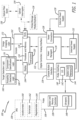
- the console 102 may house a variety of components of the ultrasound imaging system 100.
- a processor 116 and memory 118 such as random-access memory (RAM) or non-volatile memory - e.g., electrically erasable programmable read-only memory EEPROM may be included in the console 102 for controlling functions of the ultrasound imaging system 100, as well as for executing various logic operations or algorithms during operation of the ultrasound imaging system 100 in accordance with executable instructions 120 stored in the memory 118 for execution by the processor 116.
- RAM random-access memory
- non-volatile memory - e.g., electrically erasable programmable read-only memory EEPROM may be included in the console 102 for controlling functions of the ultrasound imaging system 100, as well as for executing various logic operations or algorithms during operation of the ultrasound imaging system 100 in accordance with executable instructions 120 stored in the memory 118 for execution by the processor 116.
- the console 102 is configured to instantiate by way of the instructions 120 one or more processes for adjusting a distance of activated ultrasonic transducers 148 from a predefined target (e.g., a target vein) or an area, an orientation of the activated ultrasonic transducers 148 to the predefined target or area, or both the distance and the orientation of the activated ultrasonic transducers 148 with respect to the predefined target or area, as well as process electrical signals from the ultrasound probe 106 into ultrasound images.
- the activated ultrasonic transducers 148 may be adjusted using ultrasound-imaging data, magnetic-field data, fiber-optic shape-sensing data, or a combination thereof received by the console 102.
- the console 102 may activate certain ultrasonic transducers of a 2-D array of the ultrasonic transducers 148 or moving the already activated transducers in a linear array of the ultrasonic transducers 148.
- a digital controller/analog interface 122 may be also included with the console 102 and is in communication with both the processor 116 and other system components to govern interfacing between the ultrasound probe 106 and other system components set forth herein.
- the ultrasound imaging system 100 further includes ports 124 for connection with additional components such as optional components 126 including a printer, storage media, keyboard, etc.
- the ports 124 can be implemented as universal serial bus (USB) ports, though other types of ports can be used for this connection or any other connections shown or described herein.
- a power connection 128 is included with the console 102 to enable operable connection to an external power supply 130.
- An internal power supply 132 e.g., a battery
- Power management circuitry 134 is included with the digital controller/analog interface 122 of the console 102 to regulate power use and distribution.
- a stand-alone optical interrogator 154 may be communicatively coupled to the console 102 by way of one of the ports 124.
- the console 102 may include an optical interrogator integrated into the console 502. Such an optical interrogator is configured to emit input optical signals into a companion optical-fiber stylet 156 for shape sensing with the ultrasound imaging system 100.
- the optical-fiber stylet 156 may be configured to be inserted into a lumen of a medical device such as the needle and may convey the input optical signals from the optical interrogator 154 to a number of fiber Bragg grating (FBG) sensors along a length of the optical-fiber stylet 156.
- the optical interrogator 154 may be also configured to receive reflected optical signals conveyed by the optical-fiber stylet 156 reflected from the number of the FBG sensors, the reflected optical signals may be indicative of a shape of the optical-fiber stylet 156.
- the optical interrogator 154 may be also configured to convert the reflected optical signals into corresponding electrical signals for processing by the console 102 into distance and orientation information with respect to the target and for dynamically adjusting a distance of the activated ultrasonic transducers 148, an orientation of the activated ultrasonic transducers 148, or both the distance and the orientation of the activated ultrasonic transducers 148 with respect to the target (e.g., a target vein) or the medical device (e.g., a needle) when it is brought into proximity of the target.
- the distance and orientation of the activated ultrasonic transducers 148 may be adjusted with respect to the vein as the target.
- An image plane may be established by the activated ultrasonic transducers 148 being disposed at a particular angle to the target vein based on the orientation of the target vein (e.g., perpendicular or parallel among other configurations).
- an image plane can be established by the activated ultrasonic transducers 148 being perpendicular to a medical-device plane including the needle 204.
- the distance and orientation information may also be used for displaying an iconographic representation of the medical device on the display.
- the display screen 104 may be integrated into (or connected to) the console 102 to provide a GUI and display information for a clinician in a form of ultrasound images of the target acquired by the ultrasound probe 106.
- the ultrasound imaging system 100 may enable the distance and orientation of a magnetized medical device such as the needle to be superimposed in real-time atop an ultrasound image of the target, thus enabling a clinician to accurately guide the magnetized medical device to the intended target (e.g., the vein).
- the display screen 104 can alternatively be separate from the console 102 and communicatively (e.g., wirelessly) coupled thereto.
- a console button interface 136 may be used to immediately call up a desired mode to the display screen 104 by the clinician for assistance in an ultrasound-based medical procedure.
- the display screen 104 may be implemented as an LCD device.
- the ultrasound probe 106 may optionally include an internal measurement unit (IMU) 158 that may house and accelerometer 160, a gyroscope 162 and a magnetometer 164.
- the ultrasound probe 106 may be employed in connection with ultrasound-based visualization of a target such as the vein in preparation for inserting the needle or another medical device into the target. Such visualization gives real-time ultrasound guidance and assists in reducing complications typically associated with such insertion, including inadvertent arterial puncture, hematoma, pneumothorax, etc.
- the ultrasound probe 106 may be configured to provide to the console 102 electrical signals corresponding to the ultrasound-imaging data, the magnetic-field data, the shape-sensing data, or a combination thereof for the real-time ultrasound needle guidance.
- target detection logic 166 may be executed by the processor 116 to detect vessels and other anatomic targets in the ultrasound images.
- the target detection logic 166 may include pulsatility detection logic 168 and component identification logic 170.
- the target detection logic 166 may use pulsatility detection logic 168 and component identification logic 170.
- the pulsatility detection logic 168 may compare a sequence of images of a vessel to detect pulses indicated by periodic changes in dimensions of the vessel (e.g., expansions in a diameter of the vessel).
- the target detection logic 106 may also detect bones by identifying tissues with high density based on color saturation in the ultrasound images.
- the component identification logic 170 may analyze reflection of echoes in each ultrasound image.
- the respective logics 166, 168 and 170 may be stored on a non-transitory computer-readable medium of the console 102.
- An image cropping logic 172 may be executed on the processor 116 to crop images with the detected anatomic target (e.g., a target vein) so the anatomic target is in the center of the cropped image that of a total ultrasound imaging area as will be discussed in more detail herein.
- “cropping” may refer to reducing the amount of the ultrasound image that is displayed. Further, cropping may include increasing a magnification of the cropped portion of the ultrasound image.
- the target detection logic 166 and image cropping logic 172 may collectively be referred to as "console logic" or "logic of the console 102"; however, the term console logic may also include reference to any of the other logic modules illustrated in FIG. 1 .
- a probe connected to a console is shown in accordance with some embodiments.
- the ultrasound probe 200 is connected to a console 102 over a wired connection.
- a wireless connection may be used.
- the ultrasound probe 200 includes a body that may house a console operatively connected to an ultrasound imaging device 220.
- the ultrasound probe 200 may be configured to assist a user such as a clinician in insertion of an access device such as a needle into a target vein 210 of a patient.
- Ultrasonic transducers located in a head 202 of the ultrasound probe are configured to capture 2-D ultrasound images 222 to be displayed on a screen 104 of the console 102.
- the head 202 may house a linear array of the ultrasonic transducers (not shown) or a 2-D array of the ultrasonic transducers.
- the ultrasonic transducers may be implemented as piezoelectric transducers or capacitive micro-machined ultrasonic transducers (CMUTs).
- CMUTs capacitive micro-machined ultrasonic transducers
- the transducers may be configured to maintain the target in an image plane or switch to a different image plane (e.g., from a perpendicular plane to a medical-device plane to a plane parallel to the medical-device plane) including the target.
- the ultrasound probe 200 is configured with the moveable linear array of the ultrasonic transducers, the ultrasonic transducers may be already activated for ultrasound imaging. For example, a subset of the ultrasonic transducers or all of the available ultrasonic transducers may be moved together on the moveable linear array as needed for ultrasound imaging based on the ultrasound-imaging data to maintain the target in an image plane established by the activated ultrasonic transducers or to switch to a different image plane including the target.
- the probe head 202 may be placed against the skin of a patient proximate to a needle-insertion site so the activated ultrasonic transducers in the probe head 202 may generate and emit the generated ultrasound signals into the patient as a sequence of pulses. Then, the transmitters (not shown) may receive reflected ultrasound signals (i.e., reflections of the generated ultrasonic pulses from the patient's body). The reflected ultrasound signals may be converted into corresponding electrical signals for processing into ultrasound images by the console of the probe 200.
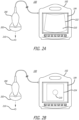
- a clinician may employ the ultrasound imaging system 100 depicted in FIG. 2A to determine a suitable insertion site and establish vascular access to the target vein 210 with a needle or another medical device.
- the ultrasound imaging system 100 depicted in FIG. 2A is capable of target vein 210 visualization in the total available ultrasound image 222 shown on a display 104 of a console 102.
- the image data is received from the probe 200 into the console 102 depicted in FIG. 1 .
- the target detection logic 166 may process the image data to render the ultrasound images in the total available ultrasound image 222.
- the target detection logic 166 may use pulsatility detection logic 168 and component identification logic 170.
- the pulsatility detection logic 168 may compare a sequence of images of a vessel to detect pulses indicated by periodic changes in dimensions of the vessel (e.g., expansions in a diameter of the vessel).
- the component identification logic 170 may also detect bones by identifying tissues with high density based on color saturation in the ultrasound images.
- the component identification logic 170 may analyze reflection of echoes in each image. This can be implemented using thresholds set to define organs, blood vessels and bones.
- the respective logics may be stored on a non-transitory computer-readable medium of the console 102.
- the target detection logic 166 may process the image data including the target vein 210 to render the ultrasound images 222.
- the ultrasound imaging system 100 depicted in FIG. 2A may be used for insertion procedure site assessment. Note that while the ultrasound probe assembly depicted in FIG. 2A has a generic shape, the ultrasound probe 200 may be of a different shape as long as the probe captures the insertion site and a target vein 210.
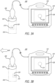
- the probe 200 is shown as being connected to the console 102, which is displaying a target vein 210 in a cropped image 224 of a total available ultrasound image.
- the ultrasound probe 200 is connected to the console 102 over a wired connection.
- a wireless connection may be used.
- the ultrasound probe 200 includes a body that may house a console operatively connected to an ultrasound imaging device 220.
- the ultrasound probe 200 may be configured to assist a user such as a clinician in insertion of an access device such as a needle into a target vein 210 of a patient.
- the probe head 202 may be placed against the skin of a patient proximate to a needle-insertion site so the activated ultrasonic transducers in the probe head 202 may generate and emit ultrasound signals into the patient as a sequence of pulses. Then, the transmitters (not shown) may receive reflected ultrasound signals (i.e., reflections of the generated ultrasonic pulses from the patient's body). The reflected ultrasound signals may be converted into corresponding electrical signals for processing into ultrasound images by the console of the probe 200.
- a clinician may employ the ultrasound imaging system 100 depicted in FIG. 2B to determine a suitable insertion site and establish vascular access to the target vein 210 with a needle or another medical device.
- the ultrasound imaging system 100 depicted in FIG. 2B is capable of imaging and detecting a target vein 210 and providing visualizations as a cropped image 320 shown on the display 104 of the console 102.
- the cropped image 224 is a subset of the total ultrasound image.
- the image data is received from the probe 200 by the console 102 as depicted in FIG. 1 .
- the target detection logic 166 running on the console 102 may process the image data to detect an anatomic target (the target vein 210) within the ultrasound images.
- the target detection logic 166 may use pulsatility detection logic 168 and component identification logic 170 depicted in FIG. 1 .
- the pulsatility detection logic 168 may compare a sequence of images of a vessel to detect pulses indicated by periodic changes in dimensions of the vessel (e.g., expansions in a diameter of the vessel).
- the component identification logic 170 may also detect bones by identifying tissues with high density based on color saturation in the ultrasound images.
- the component identification logic 170 may analyze reflection of echoes in each ultrasound image. This can be implemented using thresholds set to define anatomic targets such as organs, blood vessels, bones, etc.
- the cropped image 224 may be magnified to fill, or substantially fill, the display 104. As seen in a comparison of FIGS. 2A-2B , the image of the target vein 210 in FIG. 2B appears larger than the image of the target vein 210 in FIG. 2A , which indicates a magnification has occurred with the cropped image 224.
- the ultrasound image of the imaging area 300 is provided to the console 102 where the console logic processes the ultrasound image.
- the target detection logic 166 analyzes the ultrasound image to detect the target vein 210.
- the target detection logic 166 may place a bounding box surrounding the target vein 210 or may detect coordinates of a box around the target vein 210.
- the term "box” is not limited to a square or rectangle but may refer to any other shape, such as a circle, oval, etc.
- the image cropping logic 172 crops the ultrasound image illustrating imaging area 300 around the image of the target vein 210 in such a way that the target vein 210 is located in the center of the cropped image 320.
- the image cropping logic 172 when executed by the processor 116, may crop the ultrasound image illustrating the imaging area 300 at the bounding box or coordinates determined by the target detection logic 166. Then, the cropped image 320 containing the target vein 210 may be displayed on the screen of the console 102.
- FIG. 3B a view of visualization of a cropped image of a target vein when the probe shifts is shown in accordance with some embodiments.
- the probe 200 inadvertently shifts in a first direction, e.g., to the left.
- the shift of the probe 200 may produce a corresponding shift of the location of the target vein 210 within the imaging area 300, where the corresponding shift of the target vein 210 may be thought of as being in a second direction opposite the first direction.
- logic of the ultrasound imaging system 100 is configured to detect the target vein 210 and display an image on the console 102 where the target vein 210 is displayed in the center of the image (i.e., compensating for the shift of the probe 200). Therefore, even as the probe 200 may be inadvertently shifted, the image displayed by the console 102 does maintains the target vein 210 at the center of the displayed image; thus, enabling the clinician to continue focusing on the target vein 210 itself as opposed to focusing on the inadvertent shift of the probe 200.
- the cropped image 320 advantageously does not change in response to the shifting of the probe 200.
- the ultrasound imaging system 100 may identify and distinguish anatomic targets such as the target vein 210. Then, the ultrasound imaging system 100 may identify the anatomic target and perform image tracking of that target.
- the console 102 of the ultrasound imaging system 100 may employ console logic (e.g., target detection logic 166 and image cropping logic 172, as referenced above) to receive a sequence of ultrasound images (or a continuous signal) from the probe 200. Further, the console logic may repeatedly detect the target vein 210 within each image and may crop the current image for visualization (e.g., as the cropped image 320). This way, the display of the cropped image 320 of the target vein 210 remains unaffected by the shifting of the probe 200 allowing the clinician to advantageously maintain sight of the visualization of the target vein 210.
- console logic e.g., target detection logic 166 and image cropping logic 172, as referenced above
- the ultrasound imaging system 100 may retain and communicate information on the location of the identified target vein 210.
- the console logic may determine that a shift of the probe 200 has resulted in the target vein 210 being within a threshold distance from an edge of the imaging area 300 and in response, generate a warning or indication (e.g., such as the warning 322) that is configured to inform the user (e.g., a clinician) that the target vein 210 may soon be out of sight of the probe 200 due to shifts or movement of the probe 200.
- a warning or indication e.g., such as the warning 322
- the console logic may detect the target vein 210 in each ultrasound image received from the probe 200.
- the console logic provides a "movement warning" alert that is displayed on the display 104, e.g., as an overlay on the cropped image 320.
- the console logic may detect the location of the target vein 210 relative to boundaries of the total ultrasound image area 300.
- the visual alert may be accompanied by an arrow indicating which way to move the probe to get away from the edge of the screen. This way, the clinician is alerted in time before losing sight of the visualization of the target vein 210.
- the "movement warning" alert may be generated by an alert generating logic component of the console logic.
- the warning or alert may be an audio alert such as beeping.
- the warning or alert may be a vibration of the probe 200, in which case the probe 200 would include a vibration motor that is communicatively coupled to the console logic.
- the warning or alert may be any combination of a visual alert, an audio alert and/or a vibration.
- the console logic can generate an alert configured to be rendered on the display 104 for viewing by the clinician.
- console logic may analyze each ultrasound image received from the probe 200 in order to detect the target vein 210.
- the console logic provides a "movement warning" alert that is displayed on the display 104, e.g., as an overlay on the cropped image 320.
- the console logic may provide a "Move Probe” message alert 326 that is displayed as an overlay over a rendering of the total imaging area 300.
- the console logic may also provide an arrow 324 that indicates the direction in which the probe needs to be moved in order to resume capturing of the target vein 210. This way, the clinician is alerted to move the probe and resume the visualization of the target vein 210.
- the probe connected to the console of FIG. 2A including imaging of a target vein and a needle is shown in accordance with some embodiments is shown.
- the ultrasound probe 200 may be connected to the console 102 via a wired or wireless connection.
- the probe head 202 may be placed against the skin of a patient proximate to a needle-insertion site so the activated ultrasonic transducers in the probe head 202 may generate and emit the generated ultrasound signals into the patient as a sequence of pulses. Then, the transmitters (not shown) may receive reflected ultrasound signals (i.e., reflections of the generated ultrasonic pulses from the patient's body).
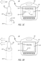
- the probe 200 is shown as being connected to the console 102, which is displaying a target vein 210 and a portion of the needle 404 in a cropped image 420 of a total available ultrasound image.
- the ultrasound imaging system 100 may be configured to obtain an ultrasound image illustrating an ultrasound imaging area 400 and render a cropped image 420 illustrating a portion of the ultrasound imaging area 400 on the display 104 of the console 102.
- target detection logic 166 of the console 102 may process the image data (ultrasound reflection data) to crop the ultrasound images and cause the rendering of the cropped image 420.
- the target detection logic 166 may use pulsatility detection logic 168 and component identification logic 170.
- the pulsatility detection logic 168 may compare a sequence of images of a vessel to detect pulses indicated by periodic changes in dimensions of the vessel (e.g., expansions in a diameter of the vessel).
- the component identification logic 170 may also detect bones by identifying tissues with high density based on color saturation in the ultrasound images.
- the component identification logic 170 may analyze reflection of echoes in each image.
- the identification of components may be implemented based on comparing characteristics of detected components (e.g., pulsatility over a plurality of images, dimensions of the detected components, color saturation, etc.) to thresholds set to define organs, blood vessels and bones. Based on the result of comparing the characteristics of detected components to the one or more thresholds, a confidence level (or score) may be determined indicating a likelihood of an identification of a particular component (e.g., a confidence score that a particular detected component is a bone or a blood vessel).
- the target detection logic 166 may also be configured to detect a needle with an ultrasound image.
- a needle such as the needle 404, may include specific and known reflection characteristics (e.g., dimensions, color saturation, etc.) such that the component identification logic 170 of the target detection logic 166 may detect and identify a needle in the same manner as discussed with respect to vessel and bone detection.
- the ultrasound probe 200 may be configured to assist a user such as a clinician in insertion of an access device, e.g., the needle 404, into a target vein 210 of a patient.
- the probe head 202 may be placed against the skin of a patient proximate to a needle-insertion site so the activated ultrasonic transducers in the probe head 202 may generate and emit ultrasound signals into the patient as a sequence of pulses. Then, the transmitters (not shown) may receive reflected ultrasound signals (i.e., reflections of the generated ultrasonic pulses from the patient's body). The reflected ultrasound signals may be converted into corresponding electrical signals for processing into ultrasound images by the console of the probe 200.
- a clinician may employ the ultrasound imaging system 100 depicted in FIG. 2B to determine a suitable insertion site and establish vascular access to the target vein 210 with a needle or another medical device.
- a determination of a boundary at which to crop the ultrasound image illustrating the imaging area 400 includes determination of the positioning of the needle 404 and its distance from the target vein 210.
- the cropped image 420 may consist of a smaller bounding box surrounding the target vein 210 when the needle 404 is in close proximity to the target vein 210 and consist of a larger bounding box when the needle 404 is further away from the target vein 210. Therefore, in both situations, the cropped image 420 illustrates the target vein 210 and the needle 404.
- the bounding box upon which the cropped image 420 is created is a predetermined size and cropping would not take into consideration a location of the needle 404.
- the term "box" is not limited to a square or rectangle but may refer to any other shape, such as a circle, oval, etc.
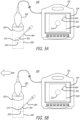
- FIG. 5B a view of visualization of a cropped image of a target vein and a portion of a needle is shown in accordance with some embodiments.
- the probe 200 inadvertently shifts in a first direction, e.g., to the left.
- the shift of the probe 200 may produce a corresponding shift of the location of the target vein 210 within the imaging area 500, where the corresponding shift of the target vein 210 may be thought of as being in a second direction opposite the first direction.
- there is no change occurs in the cropped image 520 of the vein 210 and the distal tip 501 shown to a clinician in the cropped image 520 following the accidental shifting of the probe 200.
- the cropped image 520 advantageously does not change in response to the shifting of the probe 200.
- the ultrasound imaging system 100 may identify and distinguish anatomic targets such as the target vein 210 and the distal tip 501 of the needle 404 in order to perform image tracking of the distal tip 501.
- the ultrasound imaging system 100 may employ console logic to receive a sequence of ultrasound images (or a continuous signal) from the probe 200. Then, the console logic may repeatedly detect the target vein 210 within each image and may crop the current image for visualization in the cropped image 520. This way the target vein 210 displayed in the cropped image 520 remains unaffected by the shifting of the probe 200. In other words, focus is maintained on the target vein 210 and on the tracking of the needle tip 501. Thus, the clinician advantageously does not lose sight of the visualization of the target vein 210 and tracking of the distal tip 501.
- the cropped image 520 advantageously does not change in response to the shifting of the probe 200.
- the ultrasound imaging system 100 may identify and distinguish anatomic targets such as the target vein 210. Then, the ultrasound imaging system 100 may identify the anatomic target and perform image tracking of that target.
- the console 102 of the ultrasound imaging system 100 may employ console logic (e.g., target detection logic 166 and image cropping logic 172, as referenced above) to receive a sequence of ultrasound images (or a continuous signal) from the probe 200. Further, the console logic may repeatedly detect the target vein 210 and the needle 404 within each image and may crop the current image for visualization (e.g., as the cropped image 520).
- console logic e.g., target detection logic 166 and image cropping logic 172, as referenced above
- the display of the cropped image 520 of the target vein 210 remains unaffected by the shifting of the probe 200 allowing the clinician to advantageously maintain sight of the visualization of the target vein 210 and the needle 404 as the needle 404 approaches the target vein 210.
- the ultrasound imaging system 100 may retain and communicate information on the location of the identified target vein 210.
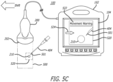
- the console logic may determine that a shift of the probe 200 has resulted in the target vein 210 and/or a distal tip 501 of the needle 404 being within a threshold distance from an edge of the imaging area 300 and in response, generate a warning or indication (e.g., such as the warning 322) that is configured to inform the user (e.g., a clinician) that the target vein 210 or the distal tip 501 of the needle 404 may soon be out of sight of the probe 200 due to shifts or movement of the probe 200.
- the warning or indication may be a visual warning displayed by the console 102 such as the warning 522 as seen in FIG. 5C .
- the warning 522 may include text, e.g., "Movement warning” and/or an indication of a direction in which to move the probe 200 relative to the target vein 210 (e.g., the arrow 324) in order to more centrally locate the ultrasound imaging area 500 over the target vein 210.
- the console logic may detect the target vein 210 and the needle 404, include a distal tip 501 of the needle 404, in each ultrasound image received from the probe 200.
- the console logic provides a "movement warning" alert that is displayed on the display 104, e.g., as an overlay on the cropped image 520.
- the console logic may detect the location of the target vein 210 relative to boundaries of the total ultrasound image area 500.
- the visual alert may be accompanied by an arrow indicating which way to move the probe to get away from the edge of the screen.
Landscapes
- Health & Medical Sciences (AREA)
- Life Sciences & Earth Sciences (AREA)
- Engineering & Computer Science (AREA)
- Surgery (AREA)
- Public Health (AREA)
- General Health & Medical Sciences (AREA)
- Nuclear Medicine, Radiotherapy & Molecular Imaging (AREA)
- Veterinary Medicine (AREA)
- Animal Behavior & Ethology (AREA)
- Biomedical Technology (AREA)
- Heart & Thoracic Surgery (AREA)
- Medical Informatics (AREA)
- Molecular Biology (AREA)
- Pathology (AREA)
- Radiology & Medical Imaging (AREA)
- Biophysics (AREA)
- Physics & Mathematics (AREA)
- Vascular Medicine (AREA)
- Computer Vision & Pattern Recognition (AREA)
- Computer Networks & Wireless Communication (AREA)
- Robotics (AREA)
- Gynecology & Obstetrics (AREA)
- Physiology (AREA)
- Ultra Sonic Daignosis Equipment (AREA)
Claims (15)
- Système d'imagerie par ultrasons (100) comprenant :une sonde ultrasonore (106, 200) incluant un réseau de transducteurs (148) configuré pour acquérir des images ultrasonores ; etune console (102) incluant un processeur (116) et un support lisible par ordinateur non transitoire sur lequel sont stockés une pluralité de modules logiques qui, lorsqu'ils sont exécutés par le processeur (116), sont configurés pour mettre en oeuvre des opérations incluant :une réception d'une image ultrasonore (222),une détection d'une ou plusieurs cible(s) dans l'image ultrasonore (222), etune génération d'une visualisation à partir de l'image ultrasonore (222) pour centrer la ou les cible(s) détectée(s) dans une partie affichée de l'image ultrasonore (222).
- Système d'imagerie par ultrasons (100) selon la revendication 1, dans lequel la génération de la visualisation inclut un recadrage de l'image ultrasonore (222) pour centrer la ou les cible(s) détectée(s) dans une partie affichée de l'image ultrasonore (222), facultativement dans lequel la génération de la visualisation inclut une augmentation d'un grossissement d'une partie recadrée de l'image ultrasonore (222) pour centrer la ou les cibles détectée(s) dans une partie affichée de l'image ultrasonore (222).
- Système d'imagerie par ultrasons (100) selon l'une quelconque des revendications 1 à 2, dans lequel la console (102) inclut un écran (104), et dans lequel la pluralité de modules logiques qui, lorsqu'ils sont exécutés par le processeur (116), sont configurés pour mettre en oeuvre d'autres opérations incluant un rendu de la visualisation de l'image ultrasonore recadrée (224, 320, 420, 520) sur un écran (104).
- Système d'imagerie par ultrasons (100) selon l'une quelconque des revendications 1 à 3, dans lequel la détection de la ou des cible(s) inclut une distinction d'une composante dans l'image ultrasonore (222) en fonction d'une variation de la saturation des couleurs dans l'image ultrasonore (222).
- Système d'imagerie par ultrasons (100) selon l'une quelconque des revendications 1 à 4, dans lequel la détection de la ou des cible(s) inclut une identification de chacune de la ou des cible(s) en tant que vaisseau sanguin, os, organe ou dispositif médical, facultativement dans lequel l'identification de chacune de la ou des cible(s) inclut une comparaison de caractéristiques de chacune de la ou des cible(s) à des seuils réglés pour définir des organes, des vaisseaux sanguins, des os ou des dispositifs médicaux.
- Système d'imagerie par ultrasons (100) selon la revendication 5, dans lequel les caractéristiques incluent un ou plusieurs élément(s) parmi une pulsatilité détectée lors de l'analyse de l'image ultrasonore (222) et d'une image ultrasonore antérieure (222), des dimensions de chacune de la ou des cible(s) ou la saturation des couleurs de chacune de la ou des cible(s), facultativement dans lequel un résultat de la comparaison des caractéristiques avec le ou les seuil(s) est un niveau de confiance pour chacune de la ou des cible(s) indiquant une probabilité d'identification d'une cible particulière.
- Système d'imagerie par ultrasons (100) selon l'une quelconque des revendications 1 à 6, dans lequel la pluralité de modules logiques qui, lorsqu'ils sont exécutés par le processeur (116), sont configurés pour mettre en oeuvre d'autres opérations incluant une détection du fait qu'au moins une première cible parmi la ou les cible(s) est à une distance seuil d'un bord de l'image ultrasonore (222), préférablement dans lequel la pluralité de modules logiques qui, lorsqu'ils sont exécutés par le processeur (116), sont configurés pour mettre en oeuvre d'autres opérations incluant une génération d'une alerte indiquant à un clinicien que la première cible est dans le seuil du bord de l'image ultrasonore (222), plus préférablement dans lequel l'alerte inclut une notification textuelle ou une flèche (324, 524) indiquant une direction dans laquelle déplacer la sonde ultrasonore (106, 200).
- Système d'imagerie par ultrasons (100) selon l'une quelconque des revendications 1 à 7, dans lequel la ou les cible(s) inclu(en)t un vaisseau sanguin et une aiguille (404), facultativement dans lequel la ou les cible(s) inclu(en)t une pointe distale (501) de l'aiguille (404).
- Procédé d'obtention d'images ultrasonores au moyen d'un système d'imagerie ultrasonore (100) incluant une sonde ultrasonore (106, 200) incluant un réseau de transducteurs (148) configuré pour acquérir des images ultrasonores, et une console (102) incluant un processeur (116) et un support lisible par ordinateur non transitoire sur lequel sont stockés une pluralité de modules logiques qui, lorsqu'ils sont exécutés par le processeur (116), sont configurés pour mettre en oeuvre des opérations, le procédé comprenant :une réception, par la console (102), d'une image ultrasonore (222) acquise par la sonde ultrasonore (106, 200) ;une détection d'une ou plusieurs cible(s) dans l'image ultrasonore (222) ; etune génération d'une visualisation à partir de l'image ultrasonore (222) pour centrer la ou les cible(s) détectée(s) dans une partie affichée de l'image ultrasonore (222).
- Procédé selon la revendication 9, dans lequel la génération de la visualisation inclut un recadrage de l'image ultrasonore (222) pour centrer la ou les cible(s) détectée(s) dans une partie affichée de l'image ultrasonore (222), facultativement dans lequel la génération de la visualisation inclut une augmentation d'un grossissement d'une partie recadrée de l'image ultrasonore (222) pour centrer la ou les cible(s) détectée(s) dans une partie affichée de l'image ultrasonore (222).
- Procédé selon l'une quelconque des revendications 9 à 10, dans lequel la détection de la ou des cible(s) inclut une distinction d'une composante dans l'image ultrasonore (222) en fonction d'une variation de la saturation des couleurs dans l'image ultrasonore (222).
- Procédé selon l'une quelconque des revendications 9 à 11, dans lequel la détection de la ou des cible(s) inclut une identification de chacune de la ou des cible(s) en tant que vaisseau sanguin, os, organe ou dispositif médical, facultativement dans lequel l'identification de chacune de la ou des cible(s) inclut une comparaison de caractéristiques de chacune de la ou des cible(s) à des seuils réglés pour définir des organes, des vaisseaux sanguins, des os ou des dispositifs médicaux.
- Procédé selon la revendication 12, dans lequel les caractéristiques incluent un ou plusieurs élément(s) parmi une pulsatilité détectée lors de l'analyse de l'image ultrasonore (222) et d'une image échographique antérieure (222), des dimensions de chacune de la ou des cible(s) ou la saturation des couleurs de chacune de la ou des cible(s), facultativement dans lequel un résultat de la comparaison des caractéristiques avec le ou les seuil(s) est un niveau de confiance pour chacune de la ou des cible(s) indiquant une probabilité d'identification d'une cible particulière.
- Procédé selon l'une quelconque des revendications 9 à 13, dans lequel la pluralité de modules logiques qui, lorsqu'ils sont exécutés par le processeur (116), sont configurés pour mettre en oeuvre d'autres opérations incluant une détection du fait qu'au moins une première cible parmi la ou les cible(s) est à une distance seuil d'un bord de l'image ultrasonore (222), préférablement dans lequel la pluralité de modules logiques qui, lorsqu'ils sont exécutés par le processeur (116), sont configurés pour mettre en oeuvre d'autres opérations incluant une génération d'une alerte indiquant à un clinicien que la première cible est dans le seuil du bord de l'image ultrasonore (222), plus préférablement dans lequel l'alerte inclut une notification textuelle ou une flèche (324, 524) indiquant une direction dans laquelle déplacer la sonde ultrasonore (106, 200).
- Procédé selon l'une quelconque des revendications 9 à 14, dans lequel la ou les cible(s) inclu(en)t un vaisseau sanguin et une aiguille (404), facultativement dans lequel la ou les cible(s) inclu(en)t une pointe distale (501) de l'aiguille (404).
Applications Claiming Priority (2)
| Application Number | Priority Date | Filing Date | Title |
|---|---|---|---|
| US202063119829P | 2020-12-01 | 2020-12-01 | |
| PCT/US2021/061267 WO2022119853A1 (fr) | 2020-12-01 | 2021-11-30 | Sonde ultrasonore à capacité de suivi de cible |
Publications (3)
| Publication Number | Publication Date |
|---|---|
| EP4251063A1 EP4251063A1 (fr) | 2023-10-04 |
| EP4251063C0 EP4251063C0 (fr) | 2025-01-01 |
| EP4251063B1 true EP4251063B1 (fr) | 2025-01-01 |
Family
ID=79164547
Family Applications (1)
| Application Number | Title | Priority Date | Filing Date |
|---|---|---|---|
| EP21835043.7A Active EP4251063B1 (fr) | 2020-12-01 | 2021-11-30 | Sonde ultrasonore à capacité de suivi de cible |
Country Status (4)
| Country | Link |
|---|---|
| US (1) | US12048491B2 (fr) |
| EP (1) | EP4251063B1 (fr) |
| CN (1) | CN114569155A (fr) |
| WO (1) | WO2022119853A1 (fr) |
Families Citing this family (21)
| Publication number | Priority date | Publication date | Assignee | Title |
|---|---|---|---|---|
| US11759166B2 (en) | 2019-09-20 | 2023-09-19 | Bard Access Systems, Inc. | Automatic vessel detection tools and methods |
| CN113952031B (zh) | 2020-07-21 | 2025-10-17 | 巴德阿克塞斯系统股份有限公司 | 磁跟踪超声探头及生成其3d可视化的系统、方法和设备 |
| CN114052905A (zh) | 2020-08-04 | 2022-02-18 | 巴德阿克塞斯系统股份有限公司 | 用于优化的医疗部件插入监测和成像增强的系统和方法 |
| CN217907826U (zh) | 2020-08-10 | 2022-11-29 | 巴德阿克塞斯系统股份有限公司 | 医学分析系统 |
| CN216135922U (zh) | 2020-09-08 | 2022-03-29 | 巴德阿克塞斯系统股份有限公司 | 动态调整超声成像系统 |
| CN114159098B (zh) | 2020-09-10 | 2026-01-02 | 巴德阿克塞斯系统股份有限公司 | 具有压力测量能力的超声探测器 |
| US12492953B2 (en) | 2020-09-18 | 2025-12-09 | Bard Access Systems, Inc. | Ultrasound probe with pointer remote control capability |
| WO2022072727A2 (fr) | 2020-10-02 | 2022-04-07 | Bard Access Systems, Inc. | Systèmes à ultrasons et procédés permettant une attention spatiale soutenue |
| CN121221162A (zh) | 2020-10-15 | 2025-12-30 | 巴德阿克塞斯系统股份有限公司 | 超声成像系统和使用其创建目标区域的三维超声图像的方法 |
| EP4247267A1 (fr) | 2020-11-24 | 2023-09-27 | Bard Access Systems, Inc. | Système à ultrasons avec connaissance de cible et d'instrument médical |
| CN114569155A (zh) | 2020-12-01 | 2022-06-03 | 巴德阿克塞斯系统股份有限公司 | 超声成像系统和用于通过其获得超声图像的方法 |
| WO2022119856A1 (fr) | 2020-12-01 | 2022-06-09 | Bard Access Systems, Inc. | Système à ultrasons avec capacité de détermination de pression et de débit |
| CN217960146U (zh) | 2021-04-15 | 2022-12-06 | 巴德阿克塞斯系统股份有限公司 | 超声成像系统 |
| US12376817B2 (en) | 2021-11-03 | 2025-08-05 | Bard Access Systems, Inc. | Optimized functionality through interoperation of doppler and image based vessel differentiation |
| US12514533B2 (en) | 2022-03-01 | 2026-01-06 | Bard Access Systems, Inc. | Ultrasound imaging system |
| US12514532B2 (en) | 2022-03-01 | 2026-01-06 | Bard Access Systems, Inc. | Ultrasound imaging system |
| EP4489661B1 (fr) | 2022-03-16 | 2025-10-29 | Bard Access Systems, Inc. | Système d'imagerie ultrasonore |
| US12102481B2 (en) | 2022-06-03 | 2024-10-01 | Bard Access Systems, Inc. | Ultrasound probe with smart accessory |
| US12137989B2 (en) * | 2022-07-08 | 2024-11-12 | Bard Access Systems, Inc. | Systems and methods for intelligent ultrasound probe guidance |
| US12564373B2 (en) | 2022-08-15 | 2026-03-03 | Bard Access Systems, Inc. | Spatially aware medical device configured for performance of insertion pathway approximation |
| US20250281158A1 (en) * | 2024-03-06 | 2025-09-11 | Biosense Webster (Israel) Ltd. | Systems and methods for location-based medical rendering |
Family Cites Families (341)
| Publication number | Priority date | Publication date | Assignee | Title |
|---|---|---|---|---|
| US3697917A (en) | 1971-08-02 | 1972-10-10 | Gen Electric | Semiconductor strain gage pressure transducer |
| US5148809A (en) | 1990-02-28 | 1992-09-22 | Asgard Medical Systems, Inc. | Method and apparatus for detecting blood vessels and displaying an enhanced video image from an ultrasound scan |
| FR2662813B1 (fr) | 1990-05-29 | 1992-08-14 | Traitement Synthese Image | Procede d'acquisition d'images d'echographie. |
| US5325293A (en) | 1992-02-18 | 1994-06-28 | Dorne Howard L | System and method for correlating medical procedures and medical billing codes |
| US5441052A (en) | 1992-12-28 | 1995-08-15 | Kabushiki Kaisha Toshiba | Color doppler-type ultrasonic diagnostic apparatus |
| US5349865A (en) | 1993-08-30 | 1994-09-27 | Kavlico Corporation | Wide-pressure-range, adaptable, simplified pressure transducer |
| US5549554A (en) | 1994-04-01 | 1996-08-27 | Advanced Cardiovascular Systems, Inc. | Catheters having separable reusable components |
| US5573529A (en) | 1994-10-31 | 1996-11-12 | Haak; Benjamin A. | Color coded medical instruments |
| US6019724A (en) | 1995-02-22 | 2000-02-01 | Gronningsaeter; Aage | Method for ultrasound guidance during clinical procedures |
| EP0835075A4 (fr) | 1995-06-30 | 1999-06-23 | Boston Scient Corp | Catheter pour imagerie ultrasonique, avec un element coupant |
| US6375615B1 (en) | 1995-10-13 | 2002-04-23 | Transvascular, Inc. | Tissue penetrating catheters having integral imaging transducers and their methods of use |
| US5908387A (en) | 1996-06-21 | 1999-06-01 | Quinton Instrument Company | Device and method for improved quantitative coronary artery analysis |
| US5775322A (en) | 1996-06-27 | 1998-07-07 | Lucent Medical Systems, Inc. | Tracheal tube and methods related thereto |
| US5879297A (en) | 1997-05-08 | 1999-03-09 | Lucent Medical Systems, Inc. | System and method to determine the location and orientation of an indwelling medical device |
| US6263230B1 (en) | 1997-05-08 | 2001-07-17 | Lucent Medical Systems, Inc. | System and method to determine the location and orientation of an indwelling medical device |
| US6129668A (en) | 1997-05-08 | 2000-10-10 | Lucent Medical Systems, Inc. | System and method to determine the location and orientation of an indwelling medical device |
| CA2240757C (fr) | 1997-07-14 | 2001-08-28 | Matsushita Electric Industrial Co., Ltd. | Dispositif de ponction de vaisseau sanguin |
| US5897503A (en) | 1997-08-01 | 1999-04-27 | Acuson Corporation | Ultrasound transducer probe having case handle grip surfaces |
| DE69823214T2 (de) | 1997-10-01 | 2005-03-10 | Boston Scientific Ltd., St. Michael | Kit zur Längenbestimmung von Kathetern vor ihrer Einführung |
| US5970119A (en) | 1997-11-18 | 1999-10-19 | Douglas Holtz (Part Interest) | Radiological scaling and alignment device |
| US20030135115A1 (en) | 1997-11-24 | 2003-07-17 | Burdette Everette C. | Method and apparatus for spatial registration and mapping of a biopsy needle during a tissue biopsy |
| KR100255730B1 (ko) | 1997-12-15 | 2000-05-01 | 이민화 | 동맥/정맥구별이가능한초음파칼라도플러영상시스템 |
| US6231546B1 (en) | 1998-01-13 | 2001-05-15 | Lumend, Inc. | Methods and apparatus for crossing total occlusions in blood vessels |
| US7713190B2 (en) | 1998-02-24 | 2010-05-11 | Hansen Medical, Inc. | Flexible instrument |
| US6004270A (en) | 1998-06-24 | 1999-12-21 | Ecton, Inc. | Ultrasound system for contrast agent imaging and quantification in echocardiography using template image for image alignment |
| US6132379A (en) | 1998-11-04 | 2000-10-17 | Patacsil; Estelito G. | Method and apparatus for ultrasound guided intravenous cannulation |
| US6524249B2 (en) | 1998-11-11 | 2003-02-25 | Spentech, Inc. | Doppler ultrasound method and apparatus for monitoring blood flow and detecting emboli |
| IL127112A0 (en) | 1998-11-18 | 1999-09-22 | Biosonix Ltd | System for measuring flow and method therefor |
| JP2000271136A (ja) | 1999-03-25 | 2000-10-03 | Toshiba Corp | 超音波治療装置及び超音波治療装置制御方法 |
| US6233476B1 (en) | 1999-05-18 | 2001-05-15 | Mediguide Ltd. | Medical positioning system |
| US7534209B2 (en) | 2000-05-26 | 2009-05-19 | Physiosonics, Inc. | Device and method for mapping and tracking blood flow and determining parameters of blood flow |
| EP1185200B1 (fr) | 1999-06-05 | 2008-01-09 | Wilson-Cook Medical Inc. | Indices destinés à un dispositif médical endoscopique |
| US6687386B1 (en) | 1999-06-15 | 2004-02-03 | Hitachi Denshi Kabushiki Kaisha | Object tracking method and object tracking apparatus |
| US6498942B1 (en) | 1999-08-06 | 2002-12-24 | The University Of Texas System | Optoacoustic monitoring of blood oxygenation |
| US6251073B1 (en) | 1999-08-20 | 2001-06-26 | Novasonics, Inc. | Miniaturized ultrasound apparatus and method |
| JP2003515423A (ja) | 1999-12-07 | 2003-05-07 | コーニンクレッカ フィリップス エレクトロニクス エヌ ヴィ | 動脈区分の複合画像列を表示する超音波画像処理方法及びシステム |
| JP2003517912A (ja) | 1999-12-21 | 2003-06-03 | コーニンクレッカ フィリップス エレクトロニクス エヌ ヴィ | 動脈の超音波複合映像シーケンスを表示するための超音波映像処理方法及び検査システム |
| WO2001047421A1 (fr) | 1999-12-28 | 2001-07-05 | Koninklijke Philips Electronics N.V. | Procede et systeme de traitement d'images ultrasonores pour afficher une sequence d'image a codage couleur d'un objet pourvu de parties mobiles |
| US6612992B1 (en) | 2000-03-02 | 2003-09-02 | Acuson Corp | Medical diagnostic ultrasound catheter and method for position determination |
| US6554774B1 (en) | 2000-03-23 | 2003-04-29 | Tensys Medical, Inc. | Method and apparatus for assessing hemodynamic properties within the circulatory system of a living subject |
| US6640976B1 (en) | 2000-06-13 | 2003-11-04 | Careguide, Inc. | Male clean intermittent catheter system |
| US6524246B1 (en) | 2000-10-13 | 2003-02-25 | Sonocine, Inc. | Ultrasonic cellular tissue screening tool |
| US7831449B2 (en) | 2001-02-02 | 2010-11-09 | Thompson Reuters (Healthcare) Inc. | Method and system for extracting medical information for presentation to medical providers on mobile terminals |
| US6592565B2 (en) | 2001-04-26 | 2003-07-15 | Zbylut J. Twardowski | Patient-tailored, central-vein catheters |
| DE60238369D1 (de) | 2001-05-23 | 2011-01-05 | Radi Medical Systems | Interaktives Messsystem |
| US7217266B2 (en) | 2001-05-30 | 2007-05-15 | Anderson R Rox | Apparatus and method for laser treatment with spectroscopic feedback |
| US6592520B1 (en) | 2001-07-31 | 2003-07-15 | Koninklijke Philips Electronics N.V. | Intravascular ultrasound imaging apparatus and method |
| WO2003022169A1 (fr) | 2001-09-12 | 2003-03-20 | Scimed Life Systems, Inc. | Systeme d'identification de dispositifs medicaux |
| US6543642B1 (en) | 2001-09-21 | 2003-04-08 | Daydots International, Inc. | Disposable glove dispenser system |
| US6733458B1 (en) | 2001-09-25 | 2004-05-11 | Acuson Corporation | Diagnostic medical ultrasound systems and methods using image based freehand needle guidance |
| JP3863414B2 (ja) | 2001-11-22 | 2006-12-27 | 株式会社東芝 | 超音波診断装置 |
| US6689067B2 (en) | 2001-11-28 | 2004-02-10 | Siemens Corporate Research, Inc. | Method and apparatus for ultrasound guidance of needle biopsies |
| US6601705B2 (en) | 2001-12-07 | 2003-08-05 | The Procter & Gamble Company | Package containing a window and performance characteristic indicator |
| US6554771B1 (en) | 2001-12-18 | 2003-04-29 | Koninklijke Philips Electronics N.V. | Position sensor in ultrasound transducer probe |
| US6746402B2 (en) | 2002-01-02 | 2004-06-08 | E. Tuncay Ustuner | Ultrasound system and method |
| US6755789B2 (en) | 2002-02-05 | 2004-06-29 | Inceptio Medical Technologies, Llc | Ultrasonic vascular imaging system and method of blood vessel cannulation |
| JP4217023B2 (ja) | 2002-02-25 | 2009-01-28 | 一郎 佐久間 | 血管内皮計測装置 |
| US7734326B2 (en) | 2002-06-20 | 2010-06-08 | Brainlab Ag | Method and device for preparing a drainage |
| US7359554B2 (en) | 2002-08-26 | 2008-04-15 | Cleveland Clinic Foundation | System and method for identifying a vascular border |
| US7697972B2 (en) | 2002-11-19 | 2010-04-13 | Medtronic Navigation, Inc. | Navigation system for cardiac therapies |
| US7599730B2 (en) | 2002-11-19 | 2009-10-06 | Medtronic Navigation, Inc. | Navigation system for cardiac therapies |
| CN1720004B (zh) | 2002-12-04 | 2012-02-08 | 皇家飞利浦电子股份有限公司 | 辅助脉管中导管的导航的设备和方法 |
| US6979294B1 (en) | 2002-12-13 | 2005-12-27 | California Institute Of Technology | Split-screen display system and standardized methods for ultrasound image acquisition and processing for improved measurements of vascular structures |
| US7927278B2 (en) | 2002-12-13 | 2011-04-19 | California Institute Of Technology | Split-screen display system and standardized methods for ultrasound image acquisition and multi-frame data processing |
| US7074187B2 (en) | 2002-12-13 | 2006-07-11 | Selzer Robert H | System and method for improving ultrasound image acquisition and replication for repeatable measurements of vascular structures |
| AU2003303047A1 (en) | 2002-12-18 | 2004-07-09 | Koninklijke Philips Electronics N.V. | Ultrasonic apparatus for estimating artery parameters |
| US20060210130A1 (en) | 2002-12-18 | 2006-09-21 | Laurence Germond-Rouet | Ultrasonic doppler system for determining movement of artery walls |
| US6749569B1 (en) | 2003-01-07 | 2004-06-15 | Esaote S.P.A. | Method and apparatus for ultrasound imaging |
| WO2004075032A2 (fr) | 2003-02-19 | 2004-09-02 | Sicel Technologies Inc. | Detecteurs de fluorescence in vivo, systeme et procedes connexes operant conjointement avec des analytes fluorescents |
| US7727153B2 (en) | 2003-04-07 | 2010-06-01 | Sonosite, Inc. | Ultrasonic blood vessel measurement apparatus and method |
| USD496596S1 (en) | 2003-04-30 | 2004-09-28 | Robert Dalrymple | Image french measuring adjunct |
| WO2004100811A1 (fr) | 2003-05-19 | 2004-11-25 | Hitachi, Ltd. | Equipement de traitement aux ultrasons |
| US20050000975A1 (en) | 2003-05-28 | 2005-01-06 | Carco Darlene Marie | Sterile surgical glove dispenser |
| US7569016B2 (en) | 2003-07-03 | 2009-08-04 | Panasonic Corporation | Ultrasonic diagnostic apparatus |
| TWI221407B (en) | 2003-08-27 | 2004-10-01 | Micro Star Int Co Ltd | Device and method for detecting the location of vein by ultrasound |
| WO2005024729A1 (fr) | 2003-09-04 | 2005-03-17 | Philips Intellectual Property & Standards Gmbh | Dispositif et procede d'affichage d'images ultrasonores d'un vaisseau |
| US7244234B2 (en) | 2003-11-11 | 2007-07-17 | Soma Development Llc | Ultrasound guided probe device and method of using same |
| WO2005070318A1 (fr) | 2004-01-20 | 2005-08-04 | Philips Intellectual Property & Standards Gmbh | Dispositif et procede de navigation d'un catheter |
| CN1933787A (zh) | 2004-01-23 | 2007-03-21 | 特拉克斯医疗有限公司 | 在体内目标位置上完成某些程序的方法和装置 |
| US9681925B2 (en) | 2004-04-21 | 2017-06-20 | Siemens Medical Solutions Usa, Inc. | Method for augmented reality instrument placement using an image based navigation system |
| US8014848B2 (en) | 2004-04-26 | 2011-09-06 | Brainlab Ag | Visualization of procedural guidelines for a medical procedure |
| EP1591074B1 (fr) | 2004-04-26 | 2008-05-21 | BrainLAB AG | Visualisation de directives procédurales pour procédures médicales |
| US20050267365A1 (en) | 2004-06-01 | 2005-12-01 | Alexander Sokulin | Method and apparatus for measuring anatomic structures |
| JP4648652B2 (ja) | 2004-06-24 | 2011-03-09 | テルモ株式会社 | 超音波診断装置および超音波診断装置の作動方法 |
| US20060004290A1 (en) | 2004-06-30 | 2006-01-05 | Smith Lowell S | Ultrasound transducer with additional sensors |
| US20060020204A1 (en) * | 2004-07-01 | 2006-01-26 | Bracco Imaging, S.P.A. | System and method for three-dimensional space management and visualization of ultrasound data ("SonoDEX") |
| US20060013523A1 (en) | 2004-07-16 | 2006-01-19 | Luna Innovations Incorporated | Fiber optic position and shape sensing device and method relating thereto |
| US20060015039A1 (en) | 2004-07-19 | 2006-01-19 | Cassidy Kenneth T | Guidewire bearing markings simplifying catheter selection |
| US7426497B2 (en) | 2004-08-31 | 2008-09-16 | Microsoft Corporation | Method and apparatus for analysis and decomposition of classifier data anomalies |
| US8016758B2 (en) * | 2004-10-30 | 2011-09-13 | Sonowise, Inc. | User interface for medical imaging including improved pan-zoom control |
| EP1815796A4 (fr) | 2004-11-17 | 2009-10-28 | Hitachi Medical Corp | Ultrasonographe et méthode d'affichage d'image par ultrason |
| US7720520B2 (en) | 2004-12-01 | 2010-05-18 | Boston Scientific Scimed, Inc. | Method and system for registering an image with a navigation reference catheter |
| US20060184029A1 (en) * | 2005-01-13 | 2006-08-17 | Ronen Haim | Ultrasound guiding system and method for vascular access and operation mode |
| US7918787B2 (en) | 2005-02-02 | 2011-04-05 | Voyage Medical, Inc. | Tissue visualization and manipulation systems |
| JPWO2006082966A1 (ja) | 2005-02-07 | 2008-06-26 | 松下電器産業株式会社 | 超音波診断装置 |
| US7892177B2 (en) | 2005-02-28 | 2011-02-22 | Scimed Life Systems, Inc. | Systems and methods for estimating the length and position of a stent to be applied within a patient |
| US7785302B2 (en) | 2005-03-04 | 2010-08-31 | C. R. Bard, Inc. | Access port identification systems and methods |
| EP1866871A4 (fr) | 2005-03-30 | 2012-01-04 | Worcester Polytech Inst | Imagerie diagnostique ultrasonore en trois dimensions a main levee a capteurs de determination de position et d'angle |
| US7680307B2 (en) | 2005-04-05 | 2010-03-16 | Scimed Life Systems, Inc. | Systems and methods for image segmentation with a multi-stage classifier |
| ES2425388T3 (es) | 2005-05-06 | 2013-10-15 | Vasonova, Inc. | Aparato para el guiado y posicionamiento de un dispositivo endovascular |
| US8075488B2 (en) | 2005-05-12 | 2011-12-13 | Compumedics Medical Innovation Pty. Ltd. | Ultrasound diagnosis and treatment apparatus |
| WO2007002685A2 (fr) | 2005-06-24 | 2007-01-04 | Volcano Corporation | Co-registration de donnees d'images graphiques representant des elements vasculaires tridimensionnels |
| US7681579B2 (en) | 2005-08-02 | 2010-03-23 | Biosense Webster, Inc. | Guided procedures for treating atrial fibrillation |
| US8147408B2 (en) | 2005-08-31 | 2012-04-03 | Sonosite, Inc. | Medical device guide locator |
| US8852111B2 (en) | 2005-09-02 | 2014-10-07 | Ultrasound Ventures, Llc | Ultrasound guidance system |
| EP1933715A4 (fr) | 2005-10-14 | 2012-08-29 | Cleveland Clinic Foundation | Systeme et procede permettant de caracteriser un tissu vasculaire |
| US8303505B2 (en) | 2005-12-02 | 2012-11-06 | Abbott Cardiovascular Systems Inc. | Methods and apparatuses for image guided medical procedures |
| WO2007092054A2 (fr) | 2006-02-06 | 2007-08-16 | Specht Donald F | procEDE et appareil permettant de visualiser les artEres coronaires A l'aide d'ultrasons |
| JP4812460B2 (ja) | 2006-02-22 | 2011-11-09 | 株式会社ユネクス | 動脈血管判定方法および装置 |
| US20070199848A1 (en) | 2006-02-28 | 2007-08-30 | Ellswood Mark R | Packaging with color-coded identification |
| US8060181B2 (en) | 2006-04-07 | 2011-11-15 | Brainlab Ag | Risk assessment for planned trajectories |
| US8172754B2 (en) | 2006-04-18 | 2012-05-08 | Panasonic Corporation | Ultrasonograph |
| US8112292B2 (en) | 2006-04-21 | 2012-02-07 | Medtronic Navigation, Inc. | Method and apparatus for optimizing a therapy |
| WO2008115188A2 (fr) | 2006-05-08 | 2008-09-25 | C. R. Bard, Inc. | Interface utilisateur et procédés pour un dispositif d'affichage sonographique |
| US20080021322A1 (en) | 2006-05-24 | 2008-01-24 | Michael Benjamin Stone | Ultrasonic imaging apparatus and method |
| US20080033759A1 (en) | 2006-08-02 | 2008-02-07 | Vastrac, Inc. | Information manager for a procedure-based medical practice |
| WO2008017998A2 (fr) | 2006-08-11 | 2008-02-14 | Koninklijke Philips Electronics, N.V. | Système à ultrasons pour l'imagerie de la circulation sanguine cérébrale et la lyse de caillot sanguin au moyen de microbulles |
| JP4886432B2 (ja) | 2006-09-04 | 2012-02-29 | ジーイー・メディカル・システムズ・グローバル・テクノロジー・カンパニー・エルエルシー | 超音波診断装置 |
| US8478377B2 (en) | 2006-10-04 | 2013-07-02 | Dexcom, Inc. | Analyte sensor |
| US20080146915A1 (en) | 2006-10-19 | 2008-06-19 | Mcmorrow Gerald | Systems and methods for visualizing a cannula trajectory |
| WO2008057478A2 (fr) | 2006-11-03 | 2008-05-15 | The Regents Of The University Of Michigan | Procédés et systèmes pour déterminer un volume d'écoulement dans un conduit sanguin ou fluidique, des propriétés de mouvement et mécaniques de structures à l'intérieur du corps |
| US20080177186A1 (en) | 2007-01-18 | 2008-07-24 | Slater Charles R | Methods and Apparatus for Determining a Treatment Volume of a Fluid Treatment Agent for Treating The Interior of a Blood Vessel |
| US20080188752A1 (en) | 2007-02-05 | 2008-08-07 | Penrith Corporation | Automated movement detection with audio and visual information |
| US20110021924A1 (en) | 2007-02-09 | 2011-01-27 | Shriram Sethuraman | Intravascular photoacoustic and utrasound echo imaging |
| US11197651B2 (en) * | 2007-03-08 | 2021-12-14 | Sync-Rx, Ltd. | Identification and presentation of device-to-vessel relative motion |
| US8781193B2 (en) | 2007-03-08 | 2014-07-15 | Sync-Rx, Ltd. | Automatic quantitative vessel analysis |
| US10433929B2 (en) | 2007-03-09 | 2019-10-08 | St. Jude Medical, Atrial Fibrillation Division, Inc. | System and method for local deformable registration of a catheter navigation system to image data or a model |
| US8038619B2 (en) | 2007-04-30 | 2011-10-18 | General Electric Company | Motor driver for ultrasound system |
| AU2008291763A1 (en) | 2007-05-23 | 2009-03-05 | Oscillon Ltd. | Apparatus and method for guided chronic total occlusion penetration |
| US7976469B2 (en) | 2007-06-04 | 2011-07-12 | Medtronic, Inc. | Percutaneous needle guide |
| US8702609B2 (en) | 2007-07-27 | 2014-04-22 | Meridian Cardiovascular Systems, Inc. | Image-guided intravascular therapy catheters |
| US8073215B2 (en) | 2007-09-18 | 2011-12-06 | Siemens Medical Solutions Usa, Inc. | Automated detection of planes from three-dimensional echocardiographic data |
| US8818472B2 (en) | 2007-09-28 | 2014-08-26 | University Of Florida Research Foundation, Inc. | Methods and devices for noninvasive measurement of energy absorbers in blood |
| US8323202B2 (en) | 2007-11-16 | 2012-12-04 | Pneumrx, Inc. | Method and system for measuring pulmonary artery circulation information |
| US10449330B2 (en) | 2007-11-26 | 2019-10-22 | C. R. Bard, Inc. | Magnetic element-equipped needle assemblies |
| US10751509B2 (en) | 2007-11-26 | 2020-08-25 | C. R. Bard, Inc. | Iconic representations for guidance of an indwelling medical device |
| US9649048B2 (en) | 2007-11-26 | 2017-05-16 | C. R. Bard, Inc. | Systems and methods for breaching a sterile field for intravascular placement of a catheter |
| EP2992825B1 (fr) | 2007-11-26 | 2017-11-01 | C.R. Bard Inc. | Système intégré pour placement intravasculaire d'un cathéter |
| US8781555B2 (en) | 2007-11-26 | 2014-07-15 | C. R. Bard, Inc. | System for placement of a catheter including a signal-generating stylet |
| US10524691B2 (en) | 2007-11-26 | 2020-01-07 | C. R. Bard, Inc. | Needle assembly including an aligned magnetic element |
| US8849382B2 (en) | 2007-11-26 | 2014-09-30 | C. R. Bard, Inc. | Apparatus and display methods relating to intravascular placement of a catheter |
| US9521961B2 (en) | 2007-11-26 | 2016-12-20 | C. R. Bard, Inc. | Systems and methods for guiding a medical instrument |
| US20090143672A1 (en) | 2007-12-04 | 2009-06-04 | Harms Steven E | Method for mapping image reference points to facilitate biopsy using magnetic resonance imaging |
| US8073529B2 (en) | 2007-12-04 | 2011-12-06 | Civco Medical Instruments Co., Inc. | Needle guide system for use with ultrasound transducers to effect shallow path needle entry and method of use |
| US20090281413A1 (en) | 2007-12-18 | 2009-11-12 | Searete Llc, A Limited Liability Corporation Of The State Of Delaware | Systems, devices, and methods for detecting occlusions in a biological subject |
| US8172753B2 (en) * | 2008-07-11 | 2012-05-08 | General Electric Company | Systems and methods for visualization of an ultrasound probe relative to an object |
| US9022940B2 (en) | 2008-07-18 | 2015-05-05 | Joseph H. Meier | Handheld imaging devices and related methods |
| US20100063400A1 (en) | 2008-09-05 | 2010-03-11 | Anne Lindsay Hall | Method and apparatus for catheter guidance using a combination of ultrasound and x-ray imaging |
| US20120179044A1 (en) | 2009-09-30 | 2012-07-12 | Alice Chiang | Ultrasound 3d imaging system |
| WO2010029521A2 (fr) | 2008-09-15 | 2010-03-18 | Moshe Ben Chorin | Localisateur de veines et dispositifs associés |
| US8200313B1 (en) | 2008-10-01 | 2012-06-12 | Bioquantetics, Inc. | Application of image-based dynamic ultrasound spectrography in assisting three dimensional intra-body navigation of diagnostic and therapeutic devices |
| US10863970B2 (en) | 2008-12-18 | 2020-12-15 | C. R. Bard, Inc. | Needle guide including enhanced visibility entrance |
| WO2010076808A1 (fr) | 2008-12-31 | 2010-07-08 | Larsen & Tourbo Limited | Dispositif d'imagerie ultrasonore intégré avec dispositif d'affichage de forme d'onde d'oxymètre pour application d'une anesthésie régionale |
| US20100249598A1 (en) | 2009-03-25 | 2010-09-30 | General Electric Company | Ultrasound probe with replaceable head portion |
| US8355554B2 (en) * | 2009-04-14 | 2013-01-15 | Sonosite, Inc. | Systems and methods for adaptive volume imaging |
| WO2010121146A2 (fr) | 2009-04-17 | 2010-10-21 | Malek Adel M | Détection d'anévrisme |
| WO2010131136A1 (fr) | 2009-05-13 | 2010-11-18 | Koninklijke Philips Electronics, N.V. | Doppler audio de flux sanguin à ultrasons avec changement de tonalité |
| US8556815B2 (en) | 2009-05-20 | 2013-10-15 | Laurent Pelissier | Freehand ultrasound imaging systems and methods for guiding fine elongate instruments |
| US20100312121A1 (en) | 2009-06-09 | 2010-12-09 | Zhonghui Guan | Apparatus for a needle director for an ultrasound transducer probe |
| US20100324418A1 (en) | 2009-06-23 | 2010-12-23 | Essa El-Aklouk | Ultrasound transducer |
| US20110002518A1 (en) | 2009-07-01 | 2011-01-06 | General Electric Company | Method and system for processing ultrasound data |
| JP5411272B2 (ja) | 2009-07-16 | 2014-02-12 | 株式会社ユネクス | 超音波血管検査装置 |
| KR101121286B1 (ko) * | 2009-07-31 | 2012-03-23 | 한국과학기술원 | 센서의 교정을 수행하는 초음파 시스템 및 방법 |
| AU2010298333B2 (en) | 2009-09-23 | 2014-04-17 | Lightlab Imaging, Inc. | Lumen morphology and vascular resistance measurements data collection systems, apparatus and methods |
| CN102665541B (zh) | 2009-09-29 | 2016-01-13 | C·R·巴德股份有限公司 | 与用于导管的血管内放置的设备一起使用的探针 |
| JP2011072585A (ja) | 2009-09-30 | 2011-04-14 | Fujifilm Corp | 超音波プローブ |
| WO2011044421A1 (fr) | 2009-10-08 | 2011-04-14 | C. R. Bard, Inc. | Entretoises utilisées avec une sonde ultrasonore |
| US20140180116A1 (en) | 2009-10-08 | 2014-06-26 | C. R. Bard, Inc. | Coupling Structures for an Ultrasound Probe |
| WO2011066982A1 (fr) | 2009-12-03 | 2011-06-09 | Deltex Medical Limited | Procédé et dispositif de surveillance hémodynamique qui utilise une mesure combinée de débit sanguin et de pression sanguine |
| US9445780B2 (en) | 2009-12-04 | 2016-09-20 | University Of Virginia Patent Foundation | Tracked ultrasound vessel imaging |
| JP5672241B2 (ja) | 2009-12-18 | 2015-02-18 | コニカミノルタ株式会社 | 超音波診断装置およびその制御方法 |
| CA2786298A1 (fr) | 2010-01-07 | 2011-07-14 | Verathon Inc. | Dispositif, systeme et procede d'acces a un vaisseau sanguin |
| US9204858B2 (en) | 2010-02-05 | 2015-12-08 | Ultrasonix Medical Corporation | Ultrasound pulse-wave doppler measurement of blood flow velocity and/or turbulence |
| WO2011098926A1 (fr) | 2010-02-09 | 2011-08-18 | Koninklijke Philips Electronics N.V. | Appareil, système et procédé d'imagerie et de traitement à l'aide de détection optique de position |
| JP5754379B2 (ja) | 2010-02-10 | 2015-07-29 | コニカミノルタ株式会社 | 超音波診断装置および内中膜複合体厚の測定方法 |
| US8961420B2 (en) | 2010-04-01 | 2015-02-24 | Siemens Medical Solutions Usa, Inc. | System for cardiac condition detection and characterization |
| WO2011150376A1 (fr) | 2010-05-28 | 2011-12-01 | C.R. Bard, Inc. | Appareil convenant à une utilisation avec un système de guidage d'insertion d'aiguille |
| EP4122385A1 (fr) | 2010-05-28 | 2023-01-25 | C. R. Bard, Inc. | Système de guidage d'introduction pour aiguilles et composants médicaux |
| CN103228219B (zh) | 2010-08-09 | 2016-04-27 | C·R·巴德股份有限公司 | 用于超声探测器头的支撑和覆盖结构 |
| US8315812B2 (en) | 2010-08-12 | 2012-11-20 | Heartflow, Inc. | Method and system for patient-specific modeling of blood flow |
| US8553954B2 (en) | 2010-08-24 | 2013-10-08 | Siemens Medical Solutions Usa, Inc. | Automated system for anatomical vessel characteristic determination |
| US8622913B2 (en) | 2010-09-28 | 2014-01-07 | General Electric Company | Method and system for non-invasive monitoring of patient parameters |
| CN102551812B (zh) | 2010-12-09 | 2015-11-25 | Ge医疗系统环球技术有限公司 | 超声容积探头导航与控制方法和装置及超声设备 |
| WO2012088471A1 (fr) | 2010-12-22 | 2012-06-28 | Veebot, Llc | Systèmes et procédés d'introduction autonome d'une aiguille intraveineuse |
| WO2012088458A1 (fr) | 2010-12-22 | 2012-06-28 | C. R. Bard, Inc. | Aiguille-guide à angle pouvant être sélectionné |
| US20120220866A1 (en) | 2010-12-31 | 2012-08-30 | Volcano Corporation | Deep Vein Thrombosis Therapeutic Methods Using Therapeutic Inflatable Devices and Systems |
| US20120179038A1 (en) | 2011-01-07 | 2012-07-12 | General Electric Company | Ultrasound based freehand invasive device positioning system and method |
| US10485513B2 (en) | 2011-01-31 | 2019-11-26 | Analogic Corporation | Ultrasound imaging apparatus |
| US9318032B2 (en) | 2011-02-04 | 2016-04-19 | University of Pittsburgh—of the Commonwealth System of Higher Education | Hybrid physical-virtual reality simulation for clinical training capable of providing feedback to a physical anatomic model |
| US8945011B2 (en) | 2011-04-05 | 2015-02-03 | Houston Medical Robotics, Inc. | Systems and methods for accessing the lumen of a vessel |
| CA2832689A1 (fr) | 2011-04-14 | 2012-10-18 | Regents Of The University Of Minnesota | Caracterisation vasculaire utilisant l'imagerie ultrasonore |
| US20120277576A1 (en) | 2011-04-26 | 2012-11-01 | Chun Kee Lui | Echogenic infusion port catheter |
| JP5788229B2 (ja) | 2011-06-06 | 2015-09-30 | 株式会社東芝 | 超音波診断装置 |
| JP2013031651A (ja) | 2011-07-04 | 2013-02-14 | Toshiba Corp | 超音波診断装置及び超音波プローブ制御方法 |
| JP6008960B2 (ja) | 2011-07-06 | 2016-10-19 | シー・アール・バード・インコーポレーテッドC R Bard Incorporated | 挿入案内システムのためのニードル長決定および較正 |
| CN102871645A (zh) | 2011-07-11 | 2013-01-16 | 浙江大学 | 近红外成像超声血管治疗仪 |
| US9199082B1 (en) | 2011-07-27 | 2015-12-01 | Cvrx, Inc. | Devices and methods for improved placement of implantable medical devices |
| US20130041250A1 (en) | 2011-08-09 | 2013-02-14 | Ultrasonix Medical Corporation | Methods and apparatus for locating arteries and veins using ultrasound |
| US9295447B2 (en) | 2011-08-17 | 2016-03-29 | Volcano Corporation | Systems and methods for identifying vascular borders |
| CN103930037A (zh) | 2011-08-26 | 2014-07-16 | Ebm株式会社 | 血管治疗效果的血流模拟的系统、其方法及计算机软件程序 |
| US8744211B2 (en) | 2011-08-31 | 2014-06-03 | Analogic Corporation | Multi-modality image acquisition |
| CN103028185B (zh) | 2011-09-30 | 2017-04-12 | Ge医疗系统环球技术有限公司 | 基于实时容积超声波的自动血管介入装置、系统、及方法 |
| EP2763591A4 (fr) | 2011-10-09 | 2015-05-06 | Clear Guide Medical Llc | Guidage d'images in situ interventionnelles par fusion d'une vidéo ultrasonore |
| JP6252480B2 (ja) | 2011-10-21 | 2017-12-27 | 日産化学工業株式会社 | 酸化重合による共役ポリマーの改善された合成方法および関連する組成物 |
| CA2855830A1 (fr) | 2011-11-16 | 2013-05-23 | Volcano Corporation | Systeme et procede de mesure medicale |
| JP2015501686A (ja) | 2011-11-18 | 2015-01-19 | ベラソン インコーポレイテッドVerathon Inc. | 血管アクセスシステムおよびデバイス |
| WO2013088320A1 (fr) | 2011-12-16 | 2013-06-20 | Koninklijke Philips Electronics N.V. | Identification automatique d'un vaisseau sanguin par son nom |
| CN103458799B (zh) | 2012-01-10 | 2016-12-07 | 柯尼卡美能达株式会社 | 超声波诊断装置以及血管检测方法 |
| US8764663B2 (en) | 2012-03-14 | 2014-07-01 | Jeffrey Smok | Method and apparatus for locating and distinguishing blood vessel |
| US8548778B1 (en) | 2012-05-14 | 2013-10-01 | Heartflow, Inc. | Method and system for providing information from a patient-specific model of blood flow |
| BR112014029565B1 (pt) | 2012-05-31 | 2021-12-28 | Koninklijke Philips N.V. | Sistema de formação de imagens de ultrassom e método de fornecimento de imagem de ultrassom com informações de vasos |
| JP6065421B2 (ja) | 2012-06-15 | 2017-01-25 | セイコーエプソン株式会社 | 超音波プローブおよび超音波検査装置 |
| WO2013188833A2 (fr) | 2012-06-15 | 2013-12-19 | C.R. Bard, Inc. | Appareil et procédés permettant la détection d'un capuchon amovible sur une sonde à ultrasons |
| CN103505288B (zh) | 2012-06-29 | 2017-11-17 | 通用电气公司 | 超声成像方法和超声成像设备 |
| US10499878B2 (en) | 2012-07-26 | 2019-12-10 | Interson Corporation | Portable ultrasonic imaging probe including a transducer array |
| JP6051693B2 (ja) | 2012-09-03 | 2016-12-27 | セイコーエプソン株式会社 | 超音波プローブ、電子機器及び超音波診断装置 |
| US10433740B2 (en) | 2012-09-12 | 2019-10-08 | Heartflow, Inc. | Systems and methods for estimating ischemia and blood flow characteristics from vessel geometry and physiology |
| US11272845B2 (en) | 2012-10-05 | 2022-03-15 | Philips Image Guided Therapy Corporation | System and method for instant and automatic border detection |
| US9814433B2 (en) | 2012-10-24 | 2017-11-14 | Cathworks Ltd. | Creating a vascular tree model |
| US20140188440A1 (en) | 2012-12-31 | 2014-07-03 | Intuitive Surgical Operations, Inc. | Systems And Methods For Interventional Procedure Planning |
| US20150359520A1 (en) | 2013-01-22 | 2015-12-17 | Koninklijke Philips N.V. | Ultrasound probe and ultrasound imaging system |
| US10939822B2 (en) | 2013-01-24 | 2021-03-09 | Tylerton International Holdings Inc. | Body structure imaging |
| CN103961135B (zh) | 2013-02-04 | 2017-04-12 | 通用电气公司 | 用于侦测三维超声图像中导管位置的系统及方法 |
| JP2014150928A (ja) | 2013-02-07 | 2014-08-25 | Hitachi Aloka Medical Ltd | 超音波診断装置 |
| GB201303917D0 (en) | 2013-03-05 | 2013-04-17 | Ezono Ag | System for image guided procedure |
| US20140276059A1 (en) | 2013-03-12 | 2014-09-18 | Volcano Corporation | Externally imaging a body structure within a patient |
| US10555719B2 (en) | 2013-03-12 | 2020-02-11 | St. Jude Medical Puerto Rico Llc | Ultrasound assisted needle puncture mechanism |
| WO2014164992A1 (fr) | 2013-03-13 | 2014-10-09 | Miller David G | Images intravasculaires et angiographiques co-calées |
| US9057600B2 (en) | 2013-03-13 | 2015-06-16 | Hansen Medical, Inc. | Reducing incremental measurement sensor error |
| US10758308B2 (en) | 2013-03-14 | 2020-09-01 | The Spectranetics Corporation | Controller to select optical channel parameters in a catheter |
| WO2014145007A1 (fr) | 2013-03-15 | 2014-09-18 | Eagleyemed | Sonde à ultrasons |
| US10687781B2 (en) | 2013-03-15 | 2020-06-23 | Nilus Medical Llc | Hemodynamic monitoring device and methods of using same |
| EP2999411B1 (fr) | 2013-05-23 | 2020-10-07 | Cardiosonic Ltd. | Dispositifs de dénervation rénale et évaluation associée |
| KR20140140331A (ko) | 2013-05-29 | 2014-12-09 | 삼성메디슨 주식회사 | 생체에 가해지는 압력을 검출하는 초음파 시스템 및 방법 |
| JP2014233522A (ja) | 2013-06-04 | 2014-12-15 | セイコーエプソン株式会社 | 超音波測定装置および超音波測定方法 |
| US11229490B2 (en) | 2013-06-26 | 2022-01-25 | Corindus, Inc. | System and method for monitoring of guide catheter seating |
| KR20150005052A (ko) | 2013-07-04 | 2015-01-14 | 삼성메디슨 주식회사 | 대상체 정보를 제공하는 초음파 시스템 및 방법 |
| EP3027138B1 (fr) | 2013-07-29 | 2025-02-26 | Intuitive Surgical Operations, Inc. | Systèmes de capteur de forme avec détection redondante |
| US20150065916A1 (en) | 2013-08-29 | 2015-03-05 | Vasculogic, Llc | Fully automated vascular imaging and access system |
| WO2015038786A2 (fr) | 2013-09-11 | 2015-03-19 | Boston Scientific Scimed, Inc. | Systèmes et procédés de sélection et d'affichage d'images au moyen d'un système d'imagerie à ultrasons intravasculaire |
| CN106061424B (zh) * | 2013-12-20 | 2019-04-30 | 皇家飞利浦有限公司 | 用于跟踪穿刺器械的系统和方法 |
| JP6841659B2 (ja) | 2014-01-14 | 2021-03-10 | ボルケーノ コーポレイション | 血管アクセスを形成する装置及び方法 |
| US20150297097A1 (en) | 2014-01-14 | 2015-10-22 | Volcano Corporation | Vascular access evaluation and treatment |
| EP3100186B1 (fr) | 2014-01-29 | 2021-05-12 | Becton, Dickinson and Company | Système et procédé de confirmation de collecte et de suivi d'échantillons au site d'utilisation clinique |
| EP3318192B1 (fr) | 2014-01-29 | 2019-09-25 | Becton, Dickinson and Company | Dispositif électronique portable pour améliorer la visualisation lors de l'insertion d'un dispositif invasif |
| US10987088B2 (en) | 2014-07-01 | 2021-04-27 | Augusta University Research Institute, Inc. | Systems and methods for detecting intracranial pressure and volume |
| US9320493B2 (en) | 2014-07-08 | 2016-04-26 | Nadarasa Visveshwara | System and method for measuring fluidics in arteries |
| US20160026894A1 (en) | 2014-07-28 | 2016-01-28 | Daniel Nagase | Ultrasound Computed Tomography |
| KR101705120B1 (ko) * | 2014-08-28 | 2017-02-09 | 삼성전자 주식회사 | 자가 진단 및 원격 진단을 위한 초음파 진단 장치 및 초음파 진단 장치의 동작 방법 |
| US9918701B2 (en) | 2014-09-03 | 2018-03-20 | Contextvision Ab | Methods and systems for automatic control of subjective image quality in imaging of objects |
| EP2998932B1 (fr) | 2014-09-16 | 2021-01-27 | Esaote S.p.A. | Procédé et dispositif pour l'acquisition d'images à ultrasons et pour la fusion de ces images avec des images préalablement acquises |
| US20160120607A1 (en) | 2014-11-03 | 2016-05-05 | Michael Sorotzkin | Ultrasonic imaging device for examining superficial skin structures during surgical and dermatological procedures |
| EP3220828B1 (fr) | 2014-11-18 | 2021-12-22 | C.R. Bard, Inc. | Système d'imagerie à ultrasons ayant une présentation d'image automatique |
| KR20160066927A (ko) | 2014-12-03 | 2016-06-13 | 삼성전자주식회사 | 컴퓨터 보조 진단 지원 장치 및 방법 |
| WO2016092389A1 (fr) | 2014-12-10 | 2016-06-16 | Koninklijke Philips N.V. | Dispositifs, systèmes et procédés pour prédiction de resténose dans une endoprothèse |
| US10973584B2 (en) | 2015-01-19 | 2021-04-13 | Bard Access Systems, Inc. | Device and method for vascular access |
| KR20160089647A (ko) * | 2015-01-20 | 2016-07-28 | 삼성전자주식회사 | 엑스선 영상장치 및 그 제어방법 |
| US10136915B2 (en) | 2015-01-26 | 2018-11-27 | Loving Heart Medical Technology Inc. | Ultrasound needle guide apparatus |
| US10217022B2 (en) | 2015-03-06 | 2019-02-26 | Ricoh Company, Ltd. | Image acquisition and management |
| US10765400B2 (en) | 2015-04-24 | 2020-09-08 | The Government Of The United States, As Represented By The Secretary Of The Army | Vascular targeting system |
| US20180161502A1 (en) | 2015-06-15 | 2018-06-14 | The University Of Sydney | Insertion system and method |
| US10792011B2 (en) | 2015-06-23 | 2020-10-06 | Hemonitor Medical Ltd. | Systems and methods for hand-free continuous ultrasonic monitoring |
| WO2016209398A1 (fr) | 2015-06-25 | 2016-12-29 | Rivanna Medical Llc | Guidage échographique d'une sonde par rapport à des caractéristiques anatomiques |
| CN105107067B (zh) | 2015-07-16 | 2018-05-08 | 执鼎医疗科技(杭州)有限公司 | 一种红外引导超声定位的静脉穿刺系统 |
| EP3324850B1 (fr) | 2015-07-22 | 2023-11-08 | Koninklijke Philips N.V. | Capteur de forme réelle à fibre optique pour l'affichage de mesure doppler amélioré |
| US11202680B2 (en) | 2015-08-14 | 2021-12-21 | Intuitive Surgical Operations, Inc. | Systems and methods of registration for image-guided surgery |
| US11185311B2 (en) | 2015-09-17 | 2021-11-30 | Koninklijke Philips N.V. | Distinguishing lung sliding from external motion |
| WO2017096487A1 (fr) | 2015-12-10 | 2017-06-15 | 1929803 Ontario Corp. D/B/A Ke2 Technologies | Systèmes et procédés pour mesure de réponse de fluide automatisée |
| JP6547612B2 (ja) | 2015-12-14 | 2019-07-24 | コニカミノルタ株式会社 | 画像処理装置、画像処理方法、および、画像処理装置を備える超音波診断装置 |
| WO2017106748A1 (fr) | 2015-12-16 | 2017-06-22 | Glo-Tip, Llc | Procédés et appareils à réseau transducteur de suivi d'une aiguille |
| US10231789B2 (en) | 2015-12-18 | 2019-03-19 | Biosense Webster (Israel) Ltd. | Using force sensor to give angle of ultrasound beam |
| US10667787B2 (en) | 2016-03-01 | 2020-06-02 | EchoNous, Inc. | Ultrasound system with docking station and dockable ultrasound probe |
| DE102016108986A1 (de) | 2016-05-13 | 2017-11-16 | Krohne Messtechnik Gmbh | Verfahren zur Detektion von Rohrleitungsschwingungen und Messgerät |
| WO2017214428A1 (fr) | 2016-06-08 | 2017-12-14 | The United States Of America, As Represented By The Secretary, Department Of Health And Human Services | Caractérisation des tissus par tomosynthèse à ondes acoustiques |
| US20170367678A1 (en) | 2016-06-22 | 2017-12-28 | Cesare Sirtori | Ultrasound automated method for measuring the thickness of the walls of the left anterior descending, right and circumflex coronary arteries |
| US11020563B2 (en) | 2016-07-14 | 2021-06-01 | C. R. Bard, Inc. | Automated catheter-to-vessel size comparison tool and related methods |
| WO2018026878A1 (fr) | 2016-08-02 | 2018-02-08 | Avent, Inc. | Ensemble de guidage d'aiguille motorisé pour mise en place d'aiguille à ultrasons |
| US10231784B2 (en) | 2016-10-28 | 2019-03-19 | Medtronic Ardian Luxembourg S.A.R.L. | Methods and systems for optimizing perivascular neuromodulation therapy using computational fluid dynamics |
| JP6494591B2 (ja) | 2016-12-08 | 2019-04-03 | キヤノン株式会社 | 超音波プローブ及び超音波画像取得装置 |
| KR102107581B1 (ko) | 2016-12-19 | 2020-05-07 | 지멘스 메디컬 솔루션즈 유에스에이, 인크. | 초음파 프로브의 주석 정보를 제공하는 방법 및 초음파 시스템 |
| IT201700006088A1 (it) | 2017-01-20 | 2018-07-20 | Torino Politecnico | Metodo ed apparecchiatura per la rilevazione non invasiva delle condizioni di vasi sanguigni |
| US10952700B2 (en) | 2017-01-27 | 2021-03-23 | Wayne State University | Ultrasound and photoacoustic systems and methods for fetal brain assessment during delivery |
| WO2018156196A1 (fr) | 2017-02-22 | 2018-08-30 | Elkadi Hisham | Dispositif chirurgical réglable à guidage par ultrasons et techniques associées |
| WO2018187708A1 (fr) | 2017-04-07 | 2018-10-11 | Bard Access Systems, Inc. | Système de suivi et de surveillance de dispositif médical à base de fibre optique |
| JP6880963B2 (ja) | 2017-04-17 | 2021-06-02 | ニプロ株式会社 | 穿刺ガイド、及び穿刺ガイド付き超音波診断装置 |
| ES2848830T3 (es) | 2017-04-27 | 2021-08-12 | Bard Access Systems Inc | Sistema de guiado para guiar la inserción de una aguja en el cuerpo de un paciente que comprende un sistema de magnetización para conjuntos de agujas |
| EP3420914A1 (fr) | 2017-06-30 | 2019-01-02 | Koninklijke Philips N.V. | Système et procédé ultrasonore |
| US11259879B2 (en) | 2017-08-01 | 2022-03-01 | Inneroptic Technology, Inc. | Selective transparency to assist medical device navigation |
| US11950869B2 (en) | 2017-08-30 | 2024-04-09 | Intuitive Surgical Operations, Inc. | System and method for providing on-demand functionality during a medical procedure |
| EP3691533B1 (fr) * | 2017-10-04 | 2023-11-29 | Verathon INC. | Visualisation multiplan et multimode d'une zone d'intérêt pendant la visée d'une sonde à ultrasons |
| US11000206B2 (en) | 2017-10-26 | 2021-05-11 | Biosense Webster (Israel) Ltd. | Esophageal probe with transmitting coils |
| US11759168B2 (en) | 2017-11-14 | 2023-09-19 | Koninklijke Philips N.V. | Ultrasound vascular navigation devices and methods |
| US12144675B2 (en) | 2017-12-04 | 2024-11-19 | Bard Access Systems, Inc. | Systems and methods for visualizing anatomy, locating medical devices, or placing medical devices |
| EP3749215A4 (fr) | 2018-02-07 | 2021-12-01 | Atherosys, Inc. | Appareil et procédé de guidage de l'acquisition ultrasonore des artères périphériques dans le plan transversal |
| JP7047556B2 (ja) | 2018-04-10 | 2022-04-05 | コニカミノルタ株式会社 | 超音波診断装置及び穿刺針のずれ角度算出方法 |
| WO2019226626A1 (fr) | 2018-05-22 | 2019-11-28 | The Board Of Trustees Of The Leland Stanford Junior University | Combinaison conjointe de fréquence et d'angle pour une réduction de chatoiement dans une imagerie ultrasonore |
| WO2019232454A1 (fr) | 2018-05-31 | 2019-12-05 | Matt Mcgrath Design & Co, Llc | Dispositif de fixation anatomique et procédé d'utilisation associé |
| JP7357015B2 (ja) | 2018-06-29 | 2023-10-05 | コーニンクレッカ フィリップス エヌ ヴェ | 生検予測及び超音波撮像によるガイド並びに関連するデバイス、システム、及び方法 |
| EP3590436A1 (fr) | 2018-07-06 | 2020-01-08 | Koninklijke Philips N.V. | Identification d'une image optimale à partir d'un certain nombre d'images ultrasonores |
| CN112512432B (zh) | 2018-07-18 | 2024-09-03 | 皇家飞利浦有限公司 | 手持式医学扫描设备上的自动图像审查 |
| CN112533544B (zh) | 2018-08-27 | 2023-11-07 | 富士胶片株式会社 | 超声波诊断装置及超声波诊断装置的控制方法 |
| US10603479B2 (en) | 2018-08-28 | 2020-03-31 | Access For Life Inc. | Vascular access device and method |
| EP3856056A1 (fr) | 2018-09-27 | 2021-08-04 | UMC Utrecht Holding B.V. | Vascoscope |
| JP7488272B2 (ja) | 2018-10-22 | 2024-05-21 | コーニンクレッカ フィリップス エヌ ヴェ | 血管からの流れに関するパラメータを導出するための方法及びシステム |
| WO2020083660A1 (fr) | 2018-10-22 | 2020-04-30 | Koninklijke Philips N.V. | Procédés et systèmes permettant de déduire un paramètre lié à l'écoulement d'un vaisseau sanguin |
| US20200163654A1 (en) | 2018-11-28 | 2020-05-28 | Butterfly Network, Inc. | Method and apparatus to calibrate ultrasound transducers |
| JP7157649B2 (ja) | 2018-12-19 | 2022-10-20 | 富士フイルムヘルスケア株式会社 | 超音波撮像装置およびその制御方法 |
| US20200205774A1 (en) * | 2018-12-27 | 2020-07-02 | Avent, Inc. | Methods for Needle Identification on an Ultrasound Display Screen |
| US12178982B2 (en) | 2019-01-18 | 2024-12-31 | Becton, Dickinson And Company | Intravenous therapy system for blood vessel detection and vascular access device placement |
| US12544101B2 (en) * | 2019-01-30 | 2026-02-10 | Bard Access Systems, Inc. | Systems and methods for tracking medical devices |
| US20200281561A1 (en) | 2019-03-05 | 2020-09-10 | Ethos Medical, Inc. | Systems, Methods, and Devices for Instrument Guidance |
| WO2020186198A1 (fr) | 2019-03-13 | 2020-09-17 | University Of Florida Research Foundation | Système de guidage et de poursuite pour biopsie et traitement modélisés et ciblés |
| KR102176196B1 (ko) | 2019-07-09 | 2020-11-09 | (주)메디센텍 | 표재정맥 실시간 탐지 장치 및 방법 |
| US11564861B1 (en) | 2019-07-11 | 2023-01-31 | Richard Gaines | Method for treating erectile and sexual dysfunction with dual extracorporeal shockwave therapy |
| CN114206224B (zh) | 2019-07-23 | 2023-09-08 | 富士胶片株式会社 | 超声波诊断装置及超声波诊断装置的控制方法 |
| US11497467B2 (en) | 2019-08-30 | 2022-11-15 | Bard Access Systems, Inc. | Probe head-cover applicator and method thereof |
| US11759166B2 (en) | 2019-09-20 | 2023-09-19 | Bard Access Systems, Inc. | Automatic vessel detection tools and methods |
| JP7379120B2 (ja) | 2019-11-28 | 2023-11-14 | キヤノン株式会社 | 超音波診断装置、医用画像撮影装置、学習装置、超音波画像表示方法及びプログラム |
| JP7456151B2 (ja) | 2019-12-24 | 2024-03-27 | コニカミノルタ株式会社 | 超音波診断装置、超音波診断装置の制御方法、及び、超音波診断装置の制御プログラム |
| EP3888559A1 (fr) | 2020-04-02 | 2021-10-06 | Koninklijke Philips N.V. | Sonde à ultrasons, console d'utilisateur, système et procédé |
| US11883229B2 (en) | 2020-04-10 | 2024-01-30 | GE Precision Healthcare LLC | Methods and systems for detecting abnormal flow in doppler ultrasound imaging |
| CN217907826U (zh) | 2020-08-10 | 2022-11-29 | 巴德阿克塞斯系统股份有限公司 | 医学分析系统 |
| CN114159098B (zh) | 2020-09-10 | 2026-01-02 | 巴德阿克塞斯系统股份有限公司 | 具有压力测量能力的超声探测器 |
| CN114246614B (zh) | 2020-09-25 | 2025-09-23 | 巴德阿克塞斯系统股份有限公司 | 超声成像系统和最小导管长度工具 |
| WO2022072727A2 (fr) | 2020-10-02 | 2022-04-07 | Bard Access Systems, Inc. | Systèmes à ultrasons et procédés permettant une attention spatiale soutenue |
| CN121221162A (zh) | 2020-10-15 | 2025-12-30 | 巴德阿克塞斯系统股份有限公司 | 超声成像系统和使用其创建目标区域的三维超声图像的方法 |
| EP4247267A1 (fr) | 2020-11-24 | 2023-09-27 | Bard Access Systems, Inc. | Système à ultrasons avec connaissance de cible et d'instrument médical |
| CN114569155A (zh) | 2020-12-01 | 2022-06-03 | 巴德阿克塞斯系统股份有限公司 | 超声成像系统和用于通过其获得超声图像的方法 |
| WO2022119856A1 (fr) | 2020-12-01 | 2022-06-09 | Bard Access Systems, Inc. | Système à ultrasons avec capacité de détermination de pression et de débit |
| CN217907828U (zh) | 2021-04-15 | 2022-11-29 | 巴德阿克塞斯系统股份有限公司 | 配置为检测目标区域内的一个或多个血管的医疗设备系统 |
| CN217960146U (zh) | 2021-04-15 | 2022-12-06 | 巴德阿克塞斯系统股份有限公司 | 超声成像系统 |
| WO2023059512A1 (fr) | 2021-10-04 | 2023-04-13 | Bard Access Systems, Inc. | Modification d'image ultrasonore non uniforme de sous-régions ciblées |
| WO2023076268A1 (fr) | 2021-10-25 | 2023-05-04 | Bard Access Systems, Inc. | Ultrasons doppler haute fidélité utilisant une détection de vaisseau pour une orientation relative |
| WO2023081220A1 (fr) | 2021-11-03 | 2023-05-11 | Bard Access Systems, Inc. | Détection de veine-artère basée sur doppler pour évaluation vasculaire |
| US12376817B2 (en) | 2021-11-03 | 2025-08-05 | Bard Access Systems, Inc. | Optimized functionality through interoperation of doppler and image based vessel differentiation |
| CN219661679U (zh) | 2021-11-16 | 2023-09-12 | 巴德阿克塞斯系统股份有限公司 | 医疗系统 |
| US20230201539A1 (en) | 2021-12-23 | 2023-06-29 | Bard Access Systems, Inc. | U Guide for Scalpel Tip |
| US12514533B2 (en) | 2022-03-01 | 2026-01-06 | Bard Access Systems, Inc. | Ultrasound imaging system |
| US12514532B2 (en) | 2022-03-01 | 2026-01-06 | Bard Access Systems, Inc. | Ultrasound imaging system |
| EP4489661B1 (fr) | 2022-03-16 | 2025-10-29 | Bard Access Systems, Inc. | Système d'imagerie ultrasonore |
| US20240065673A1 (en) | 2022-08-24 | 2024-02-29 | Bard Access Systems, Inc. | Ultrasound Smart Port Accessory |
-
2021
- 2021-11-30 CN CN202111443175.6A patent/CN114569155A/zh active Pending
- 2021-11-30 EP EP21835043.7A patent/EP4251063B1/fr active Active
- 2021-11-30 US US17/538,911 patent/US12048491B2/en active Active
- 2021-11-30 WO PCT/US2021/061267 patent/WO2022119853A1/fr not_active Ceased
Also Published As
| Publication number | Publication date |
|---|---|
| EP4251063C0 (fr) | 2025-01-01 |
| EP4251063A1 (fr) | 2023-10-04 |
| US12048491B2 (en) | 2024-07-30 |
| US20220168050A1 (en) | 2022-06-02 |
| CN114569155A (zh) | 2022-06-03 |
| WO2022119853A1 (fr) | 2022-06-09 |
Similar Documents
| Publication | Publication Date | Title |
|---|---|---|
| EP4251063B1 (fr) | Sonde ultrasonore à capacité de suivi de cible | |
| US12165315B2 (en) | Ultrasound system with pressure and flow determination capability | |
| US12376817B2 (en) | Optimized functionality through interoperation of doppler and image based vessel differentiation | |
| US12369882B2 (en) | Dynamically adjusting ultrasound-imaging systems and methods thereof | |
| US20230135562A1 (en) | Doppler-Based Vein-Artery Detection for Vascular Assessment | |
| CN116019486A (zh) | 使用脉管检测进行相对定向的高保真多普勒超声 | |
| US12137989B2 (en) | Systems and methods for intelligent ultrasound probe guidance | |
| CN219323439U (zh) | 超声成像系统和超声探测器装置 | |
| US20160000399A1 (en) | Method and apparatus for ultrasound needle guidance | |
| CN117582288A (zh) | 配置用于执行插入路径近似的空间感知医疗设备 | |
| CN116077087A (zh) | 用于启用人工智能的超声关联的系统和方法 | |
| US20220241024A1 (en) | Ultrasound object point tracking | |
| EP3804629A1 (fr) | Suivi de point d'objet ultrasonore |
Legal Events
| Date | Code | Title | Description |
|---|---|---|---|
| STAA | Information on the status of an ep patent application or granted ep patent |
Free format text: STATUS: UNKNOWN |
|
| STAA | Information on the status of an ep patent application or granted ep patent |
Free format text: STATUS: THE INTERNATIONAL PUBLICATION HAS BEEN MADE |
|
| PUAI | Public reference made under article 153(3) epc to a published international application that has entered the european phase |
Free format text: ORIGINAL CODE: 0009012 |
|
| STAA | Information on the status of an ep patent application or granted ep patent |
Free format text: STATUS: REQUEST FOR EXAMINATION WAS MADE |
|
| 17P | Request for examination filed |
Effective date: 20230626 |
|
| AK | Designated contracting states |
Kind code of ref document: A1 Designated state(s): AL AT BE BG CH CY CZ DE DK EE ES FI FR GB GR HR HU IE IS IT LI LT LU LV MC MK MT NL NO PL PT RO RS SE SI SK SM TR |
|
| DAV | Request for validation of the european patent (deleted) | ||
| DAX | Request for extension of the european patent (deleted) | ||
| GRAP | Despatch of communication of intention to grant a patent |
Free format text: ORIGINAL CODE: EPIDOSNIGR1 |
|
| STAA | Information on the status of an ep patent application or granted ep patent |
Free format text: STATUS: GRANT OF PATENT IS INTENDED |
|
| INTG | Intention to grant announced |
Effective date: 20240918 |
|
| GRAS | Grant fee paid |
Free format text: ORIGINAL CODE: EPIDOSNIGR3 |
|
| GRAA | (expected) grant |
Free format text: ORIGINAL CODE: 0009210 |
|
| STAA | Information on the status of an ep patent application or granted ep patent |
Free format text: STATUS: THE PATENT HAS BEEN GRANTED |
|
| AK | Designated contracting states |
Kind code of ref document: B1 Designated state(s): AL AT BE BG CH CY CZ DE DK EE ES FI FR GB GR HR HU IE IS IT LI LT LU LV MC MK MT NL NO PL PT RO RS SE SI SK SM TR |
|
| REG | Reference to a national code |
Ref country code: GB Ref legal event code: FG4D |
|
| REG | Reference to a national code |
Ref country code: DE Ref legal event code: R096 Ref document number: 602021024452 Country of ref document: DE |
|
| REG | Reference to a national code |
Ref country code: CH Ref legal event code: EP |
|
| REG | Reference to a national code |
Ref country code: IE Ref legal event code: FG4D |
|
| U01 | Request for unitary effect filed |
Effective date: 20250101 |
|
| U07 | Unitary effect registered |
Designated state(s): AT BE BG DE DK EE FI FR IT LT LU LV MT NL PT RO SE SI Effective date: 20250110 |
|
| PG25 | Lapsed in a contracting state [announced via postgrant information from national office to epo] |
Ref country code: PL Free format text: LAPSE BECAUSE OF FAILURE TO SUBMIT A TRANSLATION OF THE DESCRIPTION OR TO PAY THE FEE WITHIN THE PRESCRIBED TIME-LIMIT Effective date: 20250101 |
|
| PG25 | Lapsed in a contracting state [announced via postgrant information from national office to epo] |
Ref country code: ES Free format text: LAPSE BECAUSE OF FAILURE TO SUBMIT A TRANSLATION OF THE DESCRIPTION OR TO PAY THE FEE WITHIN THE PRESCRIBED TIME-LIMIT Effective date: 20250101 |
|
| PG25 | Lapsed in a contracting state [announced via postgrant information from national office to epo] |
Ref country code: IS Free format text: LAPSE BECAUSE OF FAILURE TO SUBMIT A TRANSLATION OF THE DESCRIPTION OR TO PAY THE FEE WITHIN THE PRESCRIBED TIME-LIMIT Effective date: 20250501 Ref country code: NO Free format text: LAPSE BECAUSE OF FAILURE TO SUBMIT A TRANSLATION OF THE DESCRIPTION OR TO PAY THE FEE WITHIN THE PRESCRIBED TIME-LIMIT Effective date: 20250401 |
|
| PG25 | Lapsed in a contracting state [announced via postgrant information from national office to epo] |
Ref country code: HR Free format text: LAPSE BECAUSE OF FAILURE TO SUBMIT A TRANSLATION OF THE DESCRIPTION OR TO PAY THE FEE WITHIN THE PRESCRIBED TIME-LIMIT Effective date: 20250101 |
|
| PG25 | Lapsed in a contracting state [announced via postgrant information from national office to epo] |
Ref country code: GR Free format text: LAPSE BECAUSE OF FAILURE TO SUBMIT A TRANSLATION OF THE DESCRIPTION OR TO PAY THE FEE WITHIN THE PRESCRIBED TIME-LIMIT Effective date: 20250402 |
|
| PG25 | Lapsed in a contracting state [announced via postgrant information from national office to epo] |
Ref country code: CZ Free format text: LAPSE BECAUSE OF FAILURE TO SUBMIT A TRANSLATION OF THE DESCRIPTION OR TO PAY THE FEE WITHIN THE PRESCRIBED TIME-LIMIT Effective date: 20250101 |
|
| PG25 | Lapsed in a contracting state [announced via postgrant information from national office to epo] |
Ref country code: SM Free format text: LAPSE BECAUSE OF FAILURE TO SUBMIT A TRANSLATION OF THE DESCRIPTION OR TO PAY THE FEE WITHIN THE PRESCRIBED TIME-LIMIT Effective date: 20250101 |
|
| PG25 | Lapsed in a contracting state [announced via postgrant information from national office to epo] |
Ref country code: SK Free format text: LAPSE BECAUSE OF FAILURE TO SUBMIT A TRANSLATION OF THE DESCRIPTION OR TO PAY THE FEE WITHIN THE PRESCRIBED TIME-LIMIT Effective date: 20250101 |
|
| PLBE | No opposition filed within time limit |
Free format text: ORIGINAL CODE: 0009261 |
|
| STAA | Information on the status of an ep patent application or granted ep patent |
Free format text: STATUS: NO OPPOSITION FILED WITHIN TIME LIMIT |
|
| U20 | Renewal fee for the european patent with unitary effect paid |
Year of fee payment: 5 Effective date: 20251022 |
|
| 26N | No opposition filed |
Effective date: 20251002 |
|
| PGFP | Annual fee paid to national office [announced via postgrant information from national office to epo] |
Ref country code: GB Payment date: 20251023 Year of fee payment: 5 |