EP4253157B1 - Abdeckungsanordnung zur befestigung eines abdeckungselements an einem armaturenbrett eines fahrzeugs - Google Patents
Abdeckungsanordnung zur befestigung eines abdeckungselements an einem armaturenbrett eines fahrzeugs Download PDFInfo
- Publication number
- EP4253157B1 EP4253157B1 EP23165168.8A EP23165168A EP4253157B1 EP 4253157 B1 EP4253157 B1 EP 4253157B1 EP 23165168 A EP23165168 A EP 23165168A EP 4253157 B1 EP4253157 B1 EP 4253157B1
- Authority
- EP
- European Patent Office
- Prior art keywords
- panel
- protrusion
- vehicle
- cover member
- slot
- Prior art date
- Legal status (The legal status is an assumption and is not a legal conclusion. Google has not performed a legal analysis and makes no representation as to the accuracy of the status listed.)
- Active
Links
Images


Classifications
-
- B—PERFORMING OPERATIONS; TRANSPORTING
- B60—VEHICLES IN GENERAL
- B60R—VEHICLES, VEHICLE FITTINGS, OR VEHICLE PARTS, NOT OTHERWISE PROVIDED FOR
- B60R13/00—Elements for body-finishing, identifying, or decorating; Arrangements or adaptations for advertising purposes
- B60R13/02—Internal Trim mouldings ; Internal Ledges; Wall liners for passenger compartments; Roof liners
- B60R13/0206—Arrangements of fasteners and clips specially adapted for attaching inner vehicle liners or mouldings
Definitions
- the present disclosure relates to the field of cover panels or trim panels used in vehicles. More particularly, the present disclosure relates to a simple and cost-effective cover assembly for fixing a cover member to an interior trim part like a dashboard or a console of a vehicle, which prevents detachment of the cover member with the interior trim panel during an event of collision/impact of the vehicle.
- Vehicles are, generally, provided with trim panels such as decorative panels, cover members, door trim panels, and the like, in an interior of the vehicle to cover components such as sensors, motors, cameras, wirings, etc. to protect it and also to beautify the vehicle interior.
- These decorative panels or cover members are generally provided on an interior trim part like an armrest, a door panel, a dashboard, a roof, etc. of the vehicle interior.
- These cover members and/or trim panels are fixed to the corresponding trim part(s) / body part(s) of the vehicle using fasteners, such as clips, hooks, etc. Such fasteners allow ease of assembly of the decorative panels or the cover members to the body part of the vehicle and also allow disassembly of the panels if required.
- US 2012/073089 A1 discloses a fastener for a body part of a vehicle, the fastener comprising: a shank designed to be throughly accommodated in use with a slot of the body part; a hammer-like head which overhangingly extends from both sides of the shank, perpendicularly to a symmetric axis of the shank; and an elastically deformable, suction-cap-shaped flange carried by the shank on the side opposite to the head, distanced therefrom; the shank carrying two elastically deformable oblique arms, which overhangingly extend from both sides of the shank, in a direction perpendicular to the head and so as to reciprocally move away from each other towards the flange, dimensioned so as to elastically cooperate against the shank when the head is introduced through the slot, and then stretch to snappingly engage the slot when the head is rotated.
- the present disclosure relates to the field of trim panels or cover members used in vehicles. More particularly, the present disclosure relates to an improved, simple, and aesthetically pleasing cover assembly for a body panel, such as a dashboard or a console, or a door, of a vehicle, for fixing a cover member on the body panel.
- the proposed cover assembly prevents detachment and flying of the cover member during an event of collision of the vehicle.
- An aspect of the present disclosure pertains to a mounting device for preventing detachment of a cover member from a panel, such as a dashboard or a console, during an event of collision/impact of a vehicle.
- the mounting device is configured to prevent detachment and/or separation of the cover member from the panel when impact forces are exerted on the cover member and/or the panel during the collision of the vehicle, thereby preventing the flying of the cover member in a passenger compartment of the vehicle during the collision of the vehicle.
- the mounting device can include a connecting link coupled to or extended from an inner surface of the cover member and extending downward, and one or more first protrusion coupled to or extended from respective first side face of a free end portion of the connecting link.
- the one or more first protrusion is extended substantially perpendicularly or obliquely from the respective first side face of the free end portion of the connecting link.
- the mounting device can further include one or more second protrusion coupled to or extended from a second side face of the free end portion of the connecting link such that the one or more second protrusion is extended a direction substantially perpendicularly or obliquely from the free end portion of the connecting link and the one or more of first protrusion.
- the connecting link, the one or more first protrusion, and the one or more second protrusion are adapted to be received in a slot provided on the panel such that at least one of the one or more first protrusion and the one or more second protrusion is abutted with the panel for fixing and/or securing the cover member with the panel such that it prevents detachment of the cover member with the panel during an event of collision/impact of the vehicle.
- the collision can be a rear collision or a frontal collision or a side collision of the vehicle.
- the one or more first protrusion can include a pair of the first protrusions are extending in opposite directions to each other from the respective first side faces and the one or more second protrusion can include a pair of the second protrusions.
- the pair of second protrusions are configured spaced apart and extended in the same direction.
- the first protrusions and the second protrusions are adapted to be received in the slot of the panel.
- the panel can be an interior trim part like a dashboard or a console or a door panel of the vehicle.
- the slot of the panel can be plus-shaped.
- a portion, for instance, a front portion, of the slot can be arranged on an at least partially inclined surface of the panel.
- the inclined portion of the slot can be inclined with the adjacent portion of the slot and allowing ease of inserting the connecting link with the first protrusions and the second protrusions in the slot.
- the inclined front portion of the slot can allow insertion of the connecting link with the one or more first protrusion and the one or more second protrusion in the slot without tiling the cover member at a high angular position with respect to the panel, thereby facilitating ease of assembly of the cover member on the panel.
- the slot of the panel can include an insertion region having a width such that the connecting link with the one or more first protrusion can be received through the insertion region.
- the width of the insertion region can be substantially equal to a width of the one or more first protrusion.
- the slot can include one or more holding region adjacent to the insertion region and extended in a direction opposite to the insertion region.
- the holding region can have a width such that at least one of the one or more first protrusion and the one or more second protrusion can be abutted/engaged with the panel in a corresponding portion adjacent to the holding region in case of collision/impact of the vehicle to prevent detachment of the cover member.
- the width of each holding region can be less than the width of the insertion region.
- the width of each holding region can be equal to the width of the free end portion of the connecting link.
- the present disclosure provides a cover assembly for an interior of a vehicle.
- the proposed cover assembly can include a cover member having one or more mounting device, and a panel/interior trim part comprising one or more slot to receive a portion of the one or more mounting device to fix and/or secure the cover member with the panel/ interior trim part such that during an event of collision/impact of the vehicle the mounting device prevents the detachment of the cover member from the panel.
- the cover member of the cover assembly can include a L-shaped hook/clipping element, like a snap-fit adapted to be hooked or clipped to the panel.
- the panel can be a dashboard or a console or a door of the vehicle.
- Each mounting device can include a connecting link coupled to or extended from the cover member and extending downward, and one or more first protrusion coupled to or extended from respective first side face of a free end portion of the connecting link.
- the one or more first protrusion can be extended substantially perpendicularly or obliquely from the free end portion of the connecting link.
- Each mounting device can further include one or more second protrusion coupled to or extended from a second side face of the free end portion of the connecting link such that the one or more second protrusion can be extended perpendicularly from the free end portion of the connecting link and the one or more first protrusion.
- the one or more first protrusion can include a pair of the first protrusions extending in opposite directions to each other, and the one or more second protrusion can include a pair of the second protrusions.
- the pair of second protrusions are configured spaced apart and extended in the same direction.
- the first protrusions and the second protrusions are adapted to be received in the slot of the panel.
- the panel can be an interior trim part like a dashboard or a console or a door of a vehicle.
- the connecting link, the one or more first protrusion, and the one or more second protrusion of each mounting device are adapted to be received in the corresponding one or more slot of the panel such that at least one of the one or more first protrusion and the one or more second protrusion is abutted with an inner surface of the panel to prevent detachment of the cover member with the panel during an event of collision/impact of the vehicle.
- the abutment of the one or more first protrusions and/or the one or more second protrusion with the inner surface of the panel can prevent detachment and fly of the cover member in case other hooks or metal clips of the assembly fails due to exertion of impact forces on the body panel and/or cover member during the collision of the vehicle.
- the panel can include a chamfered portion towards a front portion of each slot such that the front portion of the slot is inclined with the adjacent portion of the slot.
- the inclined front end of the slot can allow ease of inserting the connecting link with the first protrusions and the second protrusions in the slot.
- the inclination of the slot at the front end of the slot can allow insertion of the connecting link with the first protrusions and the second protrusions in the slot without tiling the cover member at a high angular position with respect to the panel.
- Each slot is plus-shaped.
- each slot of the panel can include an insertion region and one or more holding region.
- the insertion region can have a width such that the connecting link with the first protrusions are received through the insertion region.
- the holding region can have a width such that any or both of the first protrusions and the second protrusions can be abutted/engaged with the panel in a corresponding portion adjacent to the holding region to prevent detachment of the cover member from the panel during the event of collision/impact of the vehicle.
- Embodiments of the present disclosure relate to an improved, simple, robust, and cost-effective mounting device for fixing and/or securing a cover member to an interior trim part in an interior of a vehicle such that during an event of collision/impact of the vehicle the mounting device prevents the detachment of the cover member from an interior trim part. More particularly, the present disclosure relates to an improved, simple, and aesthetically pleasing cover assembly for a body panel, such as a dashboard, of a vehicle, for fixing a cover member on the body panel. The proposed cover assembly prevents the cover member from being detached and flying off during an event of collision of the vehicle.
- the proposed cover assembly can include a cover member having one or more mounting device, and a panel including one or more slot to receive a portion of the one or more mounting device to enable fixing and/or securing of the cover member with the panel.
- the panel is an interior trim part like a dashboard or a console of the vehicle.
- the cover member of the cover assembly can include a hooking member, or a snap-fit adapted to be hooked or clipped to the panel.
- Each mounting device can include a connecting link coupled to or extended from the cover member, and one or more of first protrusion coupled to or extended from respective first side face of a free end portion of the connecting link.
- the one or more of first protrusion can include a pair of first protrusions extended substantially perpendicularly or obliquely from the free end portion of the connecting link in opposite directions.
- Each mounting device can further include one or more second protrusion coupled to or extended from a second side face of the free end portion of the connecting link such that the one or more second protrusion can be extended substantially perpendicularly or obliquely from the free end portion of the connecting link and the one or more first protrusion.
- the second side face of the connecting link can be/is a surface extending substantially perpendicular or obliquely from a surface of the first side face of the connecting link.
- the one or more second protrusion can include a pair of protrusions which are configured spaced apart and extended in the same direction.
- the connecting link, the one or more first protrusion, and the one or more second protrusion of the mounting device are adapted to be inserted in the corresponding slot of the panel such that at least one of the one or more first protrusion and the one or more second protrusion are abutted/engaged with the panel to prevent detachment of the cover member with the panel during an event of collision/impact of the vehicle.
- the abutment/engagement of the one or more first protrusion and/or the one or more second protrusion with the panel can prevent the cover member from being flying off in case other hooks or metal clips of the cover assembly fails due to the exertion of impact forces on the body panel and/or the cover member during the collision of the vehicle.
- the collision can be a frontal collision or a rear collision of the vehicle.
- the panel can include a chamfered portion towards a front portion of the slot such that the front portion of the slot is inclined with the adjacent portion of the slot.
- the inclined front end of the slot can allow ease of inserting the connecting link with the first protrusions and the second protrusions in the slot.
- the inclined front end of the slot can allow insertion of the connecting link with the first protrusions and the second protrusions in the slot without tiling the cover member at a high angular position with respect to the panel.
- each slot can be a plus-shaped slot.
- each slot of the panel can include an insertion region and one or more holding region.
- the insertion region can have a width such that the connecting link with the one or more first protrusion can be received through the insertion region.
- the width of the insertion region can be substantially equal to a width of the one or more first protrusion. This restrains coming out of the first protrusions from the slot during the event of collision/impact of the vehicle.
- the holding region can be configured adjacent to the insertion region and extended in directions opposite to the insertion region.
- the holding region can have a width such that any or both of the one or more first protrusion and the one or more second protrusion can be abutted/engaged with the panel in a corresponding portion adjacent to the holding region during the event of collision/impact of the vehicle.
- the width of the holding region can be less than the width of the insertion region.
- the proposed cover assembly 100 can include a cover member 102 removably configured with a panel 104, such as a dashboard, of the vehicle as shown in FIG. 1 .
- the cover member 102 can be configured to partially cover any or combination of, but not limited to, sensors and cameras configured in the panel/dashboard 104 of the vehicle for beautifying the vehicle interior.
- the cover member 102 can include a mounting device 106 for fixing and/or securing the cover member 102 to the panel 104 in case of collision/impact of the vehicle.
- the panel 104 is provided with a slot 108 to receive a portion of the mounting device 106 to enable fixing and/or securing of the cover member 102 with the panel 104.
- Engagement of the mounting device 106 of the cover member 102 with the slot 108 of the panel 104 keeps the cover member 102 in place and avoid detachment and flying of the cover member 102 even when an impact force is exerted on the cover member 102 and/or the panel 104 during the event of collision of the vehicle.
- the cover assembly 100 can include a L-shaped hook/locator 110 provided with the cover member 102 for engagement with the L-shaped slot 112 in the panel 104.
- the cover assembly 100 can also include a clipping element 114 including a metal snap-fit portion 118 provided with the cover member 102 for clipping with an opening 116 in the panel 104.
- the mounting device 106 can be configured to prevent detachment and flying of the cover member 102 in case the L-shaped hook 110 and the clipping element 114, of the cover assembly 100, are failed or damaged due to exertion of the impact forces on the panel 104 and/or the cover member 102 during the collision of the vehicle.
- the collision can be any of a frontal collision and a rear collision of the vehicle.
- the mounting device 106 can be configured to prevent detachment of the cover member 102 from the panel 104 during the frontal collision and/or the rear collision of the vehicle, thereby preventing the cover member 102 from being flying off in a passenger compartment of the vehicle during the collision of the vehicle.
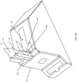
- the mounting device 106 can include a connecting link 202 coupled to or extended from an inner surface of the cover member 102 and extending vertically downward, and a pair of first protrusions 204-1 and 204-2 (hereinafter, collectively referred to as first protrusions 204, and individually referred to as first protrusion 204).
- the first protrusions 204 can be coupled to or extended from two opposite first side faces of a free end portion 206 of the connecting link 202.
- the free end portion 206 of the connecting link 202 is free end side surfaces, for example in the FIG. 2A , the connecting link 202 has a square/rectangular shape having four numbers of free end side surfaces.
- the first protrusions 204 can be extended substantially perpendicularly from the respective first side faces of the free end portion 206 of the connecting link 202 in opposite directions.
- the first protrusions 204 can be coupled to or extended from the respective first side faces of the connecting link 202 at a certain angle such that the first protrusions 204 can be inclined with the respective first side faces of the connecting link 202.
- the angle between the first protrusions 204 and the respective first side faces of the connecting link 202 can be in a range of 40 to 80 degrees.
- the mounting device 106 can further include a pair of second protrusions 208-1 and 208-2 (hereinafter, collectively referred to as second protrusions 208, and individually referred to as second protrusion 208).
- the second protrusions 208 are coupled to or extended from a second side face, of the free end portion 206 of the connecting link 202.
- the second protrusions can be extended in a direction substantially perpendicularly from the free end portion 206 of the connecting link 202 and the first protrusions 204.
- the second protrusions 208 can be coupled to or extended from the second side face of the connecting link 202 at a certain angle such that the second protrusions 208 can be inclined with the second side faces of the connecting link 202.
- the angle between the second protrusions 204 and the respective second side faces of the connecting link 202 can be in a range of 50 to 90 degrees.
- the second side face can a side surface of the free end portion 206 facing in a direction perpendicular to the first side surfaces of the free end portion 206.
- the second protrusions 208 can be configured spaced apart and extended in the same direction. In addition, the second protrusions 208 can also avoid the breakage of the mounting device 106 specifically at a junction of the first protrusions 204 and the second protrusions 208 during an event of the collision of the vehicle.
- the mounting device 106 can be rigid enough to sustain the impact forces, for example during the event of the vehicle collision.
- the mounting device 106 can be integral to the cover member 102.
- the connecting link 106, the first protrusions 204, and the second protrusions 208 of the mounting device 106 and the cover member 102 are integral parts.
- the mounting device 106 can be molded along with the cover member 102 in a main tool without addition of any slider or any extra cost, thereby minimizing manufacturing cost of the cover assembly 100.
- each second protrusion 208 can be triangular.
- the second protrusions 208 can be of any other suitable shape, such as but not limited to conical, circular, rectangular, and the like.
- the slot 108 in the panel 104 is a plus-shaped slot.
- the slot 108 can be configured to receive the connecting link 202, the first protrusions 204, and the second protrusions 208 of the mounting device 106.
- the slot 108 can include an insertion region 210 (show by a dotted rectangle) and a holding region, including a front holding region 212-1 and a rear holding region 212-2, (hereinafter, collectively referred to as holding regions 212).
- the holding region 212 (show by dotted rectangles) can be configured on opposite sides of the insertion region 210 and extended in a direction opposite to the insertion region 210.
- the insertion region 210 can have a width such that the connecting link 202 along with the first protrusions 204 can be inserted through the insertion region 210.
- the width of the insertion region 210 can be equal to the width of the first protrusions 204.
- the connecting link 202 and the first protrusions 204 can be inserted through the insertion region 210, and the second protrusions 208 can be inserted through the front or rear holding region 212-1 and 212-2 of the slot 108.
- the cover member 102 is moved into the holding region 212 until the L-hook 110 and/or the clipping element 114 is clipped on a respective L-shaped slot 112 and/or the opening 116 of the panel 104.
- the holding region 212 can have a width such that any or both of the first protrusions 204 can be held therein when the cover member 102 is displaced with respect to the panel 104, thereby preventing detachment of the cover member 102 from the panel 104.
- the width of each of the holding regions 212 can equal to a width of a free end portion 206 of the connecting link 202.
- any or both of the first protrusions 204 and the second protrusions 208 can abut with an inner surface of the panel 104 in a portion adjacent to the holding region 212 during an event of collision of the vehicle, thereby fixing and/or securing the cover member 102 with the panel 104.
- any or both the first protrusions 204 and the second protrusions 208 can abut with the inner surface of the panel 104 in the portion adjacent to the holding region 212 to fix and/or secure the cover member 102 with the panel 104, thereby avoiding detachment and flying off the cover member 102.
- the abutment of any or both of the first protrusions 204 and the second protrusions 208 with the inner surface of the panel 104 avoids detachment and flying of the cover member 102 even when high impact forces are exerted on the cover member 102 and/or the panel 104 during the event of collision of the vehicle.
- the abutment of any or both of the first protrusions 204 and the second protrusions 208 with the inner surface of the panel 104 avoid detachment and flying of the cover member 102 in the frontal collision as well as the rear collision of the vehicle.
- the panel 104 can include a chamfered portion 214 towards the front portion of the slot 108 such that the front portion, i.e., the front the holding region 212-1, of the slot 108 can be inclined with the adjacent portion, i.e., the insertion region 210, of the slot 108.
- the inclined front end of the slot 108 can allow ease of inserting the connecting link 202 with the first protrusions 204 and the second protrusions 208 in the slot 108.
- the inclined front end of the slot 108 can allow insertion of the connecting link 202 with the first protrusions 204 and the second protrusions 208 in the slot 108 without tiling the cover member 108 at a high angular position with respect to the panel 104, thereby facilitating ease of assembly of the cover member 102.
- the mounting device 106 of the cover assembly 100 secures the cover member 102 to the panel/dashboard 104 in the event of the vehicle collision, wherein the force applied to the cover member 102 during the collision, displaces the cover member 102 with respect to the panel 104, is used in order to bring the connecting link 202 into one of the holding regions 212 of the slot 108 of the panel 102 in which the any or both of the first protrusions 204 and the second protrusions 208 are securely held.
- the mounting device 106 can include ribs 216 coupled to or extended from the connecting link 202 to strengthen the connecting link 202.
- the proposed invention provides an improved and cost-effective mounting device for fixing a cover member to an interior trim part like a dashboard or a console or a door panel of a vehicle.
- the proposed invention provides a simple and easy to implement, and robust mounting device for ease of mounting a cover member or decorative panel on an interior trim part like a dashboard or a console or a door panel of a vehicle, which prevents detachment of the cover member or decorative panel from the interior trim part during an event of collision of the vehicle.
- the proposed invention provides an improved cover assembly for a vehicle interior, which prevents a cover member or a decorative panel from being detached from an interior trim part or a body part of a vehicle and flies off during an event of collision of the vehicle.
- the proposed invention provides a cover assembly with a mounting device with sufficient arrangement to prevent detachment and flying off of a cover member of the cover assembly in case other hooks or metal clips of the assembly fails or damage and thus unhooked/unclipped from the interior trim part or body part of the vehicle in case of collision/impact of the vehicle.
- the proposed invention provides an improved cover assembly for a vehicle interior, which can be easily assembled on a trim part / a body part such as a dashboard or a console without any major modification and can also be disassembled or removed with ease.
Landscapes
- Engineering & Computer Science (AREA)
- Mechanical Engineering (AREA)
- Vehicle Step Arrangements And Article Storage (AREA)
Claims (4)
- Abdeckungsanordnung (100) für den Innenraum eines Fahrzeugs, wobei die Abdeckungsanordnung (100) umfasst:ein Abdeckungselement (102), das eine oder mehrere Montagevorrichtungen (106) umfasst; undein Paneel (104) mit einem oder mehreren Schlitzen (108) zur Aufnahme eines Abschnitts der einen oder mehreren Montagevorrichtungen (106), um die Befestigung des Abdeckungselements (102) an dem Paneel (104) zu ermöglichen;wobei jede Montagevorrichtung (106) umfasst:ein Verbindungsglied (202), das mit dem Abdeckungselement (102) gekoppelt ist oder sich von diesem erstreckt;einen oder mehrere erste Vorsprünge (204), die mit einer jeweiligen ersten Seitenfläche eines freien Endabschnitts (206) des Verbindungsglieds (202) verbunden sind oder sich von dieser erstrecken, wobei der eine oder die mehreren ersten Vorsprünge (204) sich im Wesentlichen senkrecht oder schräg von dem freien Endabschnitt (206) des Verbindungsglieds (202) erstrecken; undeinen oder mehrere zweite Vorsprünge (208), die mit einer jeweiligen zweiten Seitenfläche des freien Endabschnitts (206) des Verbindungsglieds (202) verbunden sind oder sich von dieser erstrecken, so dass der eine oder die mehreren zweiten Vorsprünge (208) sich in einer Richtung erstrecken, die im Wesentlichen senkrecht oder schräg zu dem freien Endabschnitt (206) des Verbindungsglieds (202) und dem einen oder den mehreren ersten Vorsprüngen (204) ist,wobei das Verbindungsglied (202), der eine oder die mehreren erste Vorsprünge (204) und der eine oder die mehreren zweite Vorsprünge (208) so angepasst sind, dass sie in dem bzw. den entsprechenden einen oder mehreren Schlitzen (108) des Paneels (104) aufgenommen werden können, so dass mindestens einer von dem einen oder den mehreren ersten Vorsprüngen (204) und dem einen oder den mehreren zweiten Vorsprüngen (208) an dem Paneel (104) anliegt, um das Lösen des Abdeckungselements (102) von dem Paneel (104) während eines Kollisions-/Aufprallereignisses des Fahrzeugs zu verhindern, dadurch gekennzeichnet, dassjeder des einen oder der mehreren Schlitze (108) des Paneels (104) ein plusförmiger Schlitz ist.
- Abdeckungsanordnung (100) nach Anspruch 1, wobei der eine oder die mehreren ersten Vorsprünge (204) ein Paar erster Vorsprünge (204-1, 204-2) umfassen, die sich gegenüberliegend zueinander erstrecken, wobei der eine oder die mehreren zweiten Vorsprünge (208) ein Paar der zweiten Vorsprünge (208) umfassen, die sich in die gleiche Richtung erstrecken und voneinander beabstandet sind, und wobei das Paneel (104) ein Armaturenbrett oder eine Konsole des Fahrzeugs ist.
- Abdeckungsanordnung (100) nach Anspruch 1, wobei das Paneel (104) einen abgeschrägten Abschnitt (214) zu einem vorderen Abschnitt jedes Schlitzes (108) hin umfasst, so dass der vordere Abschnitt des Schlitzes (108) mit dem benachbarten Abschnitt des Schlitzes (108) geneigt ist.
- Abdeckungsanordnung (100) nach Anspruch 1, wobei jeder Schlitz (108) des Paneels (104) einen Einführungsbereich (210) mit einer solchen Breite aufweist, dass das Verbindungsglied (202) mit dem einen oder den mehreren ersten Vorsprüngen (204) durch den Einführungsbereich (210) aufgenommen wird; und wobei jeder Schlitz (108) des Paneels (104) einen oder mehrere Haltebereiche (212) umfasst, wobei jeder des einen oder der mehreren Haltebereiche (212) eine solche Breite aufweist, dass mindestens einer von dem einen oder den mehreren ersten Vorsprüngen (204) und dem einen oder den mehreren zweiten Vorsprüngen (208) im Falle eines Kollisions-/Aufprallereignisses des Fahrzeugs an das Paneel (104) in einem entsprechenden Abschnitt angrenzend an den Haltebereich (112) anstößt, um ein Lösen des Abdeckelements (102) von dem Paneel (104) zu verhindern.
Applications Claiming Priority (1)
| Application Number | Priority Date | Filing Date | Title |
|---|---|---|---|
| IN202221018412 | 2022-03-29 |
Publications (2)
| Publication Number | Publication Date |
|---|---|
| EP4253157A1 EP4253157A1 (de) | 2023-10-04 |
| EP4253157B1 true EP4253157B1 (de) | 2025-05-07 |
Family
ID=85781658
Family Applications (1)
| Application Number | Title | Priority Date | Filing Date |
|---|---|---|---|
| EP23165168.8A Active EP4253157B1 (de) | 2022-03-29 | 2023-03-29 | Abdeckungsanordnung zur befestigung eines abdeckungselements an einem armaturenbrett eines fahrzeugs |
Country Status (1)
| Country | Link |
|---|---|
| EP (1) | EP4253157B1 (de) |
Family Cites Families (4)
| Publication number | Priority date | Publication date | Assignee | Title |
|---|---|---|---|---|
| FR2894304A1 (fr) * | 2005-12-05 | 2007-06-08 | Raymond Et Cie Soc En Commandi | Dispositif d'assemblage de deux plaques |
| DE102006020697B3 (de) * | 2006-05-04 | 2007-04-26 | A. Raymond Et Cie | Drehverschluss |
| ITTO20090398A1 (it) * | 2009-05-26 | 2010-11-27 | Illinois Tool Works | Fermaglio avente un dispositivo di fissaggio autobloccante ad un elemento di carrozzeria di veicolo |
| US11542975B2 (en) * | 2020-05-11 | 2023-01-03 | Illinois Tool Works Inc. | Blind assembly fastener system |
-
2023
- 2023-03-29 EP EP23165168.8A patent/EP4253157B1/de active Active
Also Published As
| Publication number | Publication date |
|---|---|
| EP4253157A1 (de) | 2023-10-04 |
Similar Documents
| Publication | Publication Date | Title |
|---|---|---|
| EP1653092B1 (de) | Fahrzeugspiegelanordnung | |
| JP4870488B2 (ja) | 高固定強度の固定具 | |
| US7832693B2 (en) | Fastener | |
| US8322110B2 (en) | Trim flap-like closeout edge attachment | |
| JP2002031118A (ja) | 弾性クリップ留め具 | |
| US6039449A (en) | Retainer clip for a vehicle rearview mirror | |
| EP0743461B1 (de) | Montagevorrichtung | |
| JP2006336821A (ja) | 高固定強度の固定具 | |
| EP1281005B1 (de) | Befestigungsvorrichtung mit scherungfähigkeit | |
| JPH09226501A (ja) | 自動車の乗員拘束装置 | |
| JPS633783B2 (de) | ||
| EP4253157A1 (de) | Abdeckungsanordnung zur befestigung eines abdeckungselements an einem armaturenbrett eines fahrzeugs | |
| US7883223B1 (en) | Mirror system with rapid installation fastening components | |
| KR20030009768A (ko) | 자동차용 선바이저 장착용 클립 | |
| US12546347B2 (en) | Fastening clip assembly | |
| US20070099452A1 (en) | Apparatus of attaching part | |
| CN117445826A (zh) | 车辆装饰部件附接 | |
| US10899289B2 (en) | Reinforcing trim panel for vehicle interior | |
| EP4559759A1 (de) | Retention einer fahrzeugverkleidung | |
| JP2516212Y2 (ja) | バンパ用グリルの取付構造 | |
| JPH11104U (ja) | 車体内装部品のクリップ取付座 | |
| EP4074547A1 (de) | Befestigungsanordnung, rückblickvorrichtung und fahrzeug | |
| JPS6221976A (ja) | 特に自動車用のドア用ラツチ組立体 | |
| JP7504814B2 (ja) | クリップ | |
| KR100536607B1 (ko) | 리어 셀프트림 조립체 |
Legal Events
| Date | Code | Title | Description |
|---|---|---|---|
| PUAI | Public reference made under article 153(3) epc to a published international application that has entered the european phase |
Free format text: ORIGINAL CODE: 0009012 |
|
| STAA | Information on the status of an ep patent application or granted ep patent |
Free format text: STATUS: THE APPLICATION HAS BEEN PUBLISHED |
|
| AK | Designated contracting states |
Kind code of ref document: A1 Designated state(s): AL AT BE BG CH CY CZ DE DK EE ES FI FR GB GR HR HU IE IS IT LI LT LU LV MC ME MK MT NL NO PL PT RO RS SE SI SK SM TR |
|
| STAA | Information on the status of an ep patent application or granted ep patent |
Free format text: STATUS: REQUEST FOR EXAMINATION WAS MADE |
|
| 17P | Request for examination filed |
Effective date: 20240326 |
|
| RBV | Designated contracting states (corrected) |
Designated state(s): AL AT BE BG CH CY CZ DE DK EE ES FI FR GB GR HR HU IE IS IT LI LT LU LV MC ME MK MT NL NO PL PT RO RS SE SI SK SM TR |
|
| GRAP | Despatch of communication of intention to grant a patent |
Free format text: ORIGINAL CODE: EPIDOSNIGR1 |
|
| STAA | Information on the status of an ep patent application or granted ep patent |
Free format text: STATUS: GRANT OF PATENT IS INTENDED |
|
| INTG | Intention to grant announced |
Effective date: 20241202 |
|
| GRAS | Grant fee paid |
Free format text: ORIGINAL CODE: EPIDOSNIGR3 |
|
| GRAA | (expected) grant |
Free format text: ORIGINAL CODE: 0009210 |
|
| STAA | Information on the status of an ep patent application or granted ep patent |
Free format text: STATUS: THE PATENT HAS BEEN GRANTED |
|
| AK | Designated contracting states |
Kind code of ref document: B1 Designated state(s): AL AT BE BG CH CY CZ DE DK EE ES FI FR GB GR HR HU IE IS IT LI LT LU LV MC ME MK MT NL NO PL PT RO RS SE SI SK SM TR |
|
| REG | Reference to a national code |
Ref country code: GB Ref legal event code: FG4D |
|
| REG | Reference to a national code |
Ref country code: CH Ref legal event code: EP |
|
| REG | Reference to a national code |
Ref country code: DE Ref legal event code: R096 Ref document number: 602023003289 Country of ref document: DE |
|
| REG | Reference to a national code |
Ref country code: IE Ref legal event code: FG4D |
|
| REG | Reference to a national code |
Ref country code: NL Ref legal event code: MP Effective date: 20250507 |
|
| PG25 | Lapsed in a contracting state [announced via postgrant information from national office to epo] |
Ref country code: FI Free format text: LAPSE BECAUSE OF FAILURE TO SUBMIT A TRANSLATION OF THE DESCRIPTION OR TO PAY THE FEE WITHIN THE PRESCRIBED TIME-LIMIT Effective date: 20250507 Ref country code: ES Free format text: LAPSE BECAUSE OF FAILURE TO SUBMIT A TRANSLATION OF THE DESCRIPTION OR TO PAY THE FEE WITHIN THE PRESCRIBED TIME-LIMIT Effective date: 20250507 Ref country code: PT Free format text: LAPSE BECAUSE OF FAILURE TO SUBMIT A TRANSLATION OF THE DESCRIPTION OR TO PAY THE FEE WITHIN THE PRESCRIBED TIME-LIMIT Effective date: 20250908 |
|
| REG | Reference to a national code |
Ref country code: LT Ref legal event code: MG9D |
|
| PG25 | Lapsed in a contracting state [announced via postgrant information from national office to epo] |
Ref country code: GR Free format text: LAPSE BECAUSE OF FAILURE TO SUBMIT A TRANSLATION OF THE DESCRIPTION OR TO PAY THE FEE WITHIN THE PRESCRIBED TIME-LIMIT Effective date: 20250808 Ref country code: NO Free format text: LAPSE BECAUSE OF FAILURE TO SUBMIT A TRANSLATION OF THE DESCRIPTION OR TO PAY THE FEE WITHIN THE PRESCRIBED TIME-LIMIT Effective date: 20250807 |
|
| PG25 | Lapsed in a contracting state [announced via postgrant information from national office to epo] |
Ref country code: NL Free format text: LAPSE BECAUSE OF FAILURE TO SUBMIT A TRANSLATION OF THE DESCRIPTION OR TO PAY THE FEE WITHIN THE PRESCRIBED TIME-LIMIT Effective date: 20250507 Ref country code: PL Free format text: LAPSE BECAUSE OF FAILURE TO SUBMIT A TRANSLATION OF THE DESCRIPTION OR TO PAY THE FEE WITHIN THE PRESCRIBED TIME-LIMIT Effective date: 20250507 |
|
| REG | Reference to a national code |
Ref country code: AT Ref legal event code: MK05 Ref document number: 1792144 Country of ref document: AT Kind code of ref document: T Effective date: 20250507 |
|
| PG25 | Lapsed in a contracting state [announced via postgrant information from national office to epo] |
Ref country code: BG Free format text: LAPSE BECAUSE OF FAILURE TO SUBMIT A TRANSLATION OF THE DESCRIPTION OR TO PAY THE FEE WITHIN THE PRESCRIBED TIME-LIMIT Effective date: 20250507 |
|
| PG25 | Lapsed in a contracting state [announced via postgrant information from national office to epo] |
Ref country code: HR Free format text: LAPSE BECAUSE OF FAILURE TO SUBMIT A TRANSLATION OF THE DESCRIPTION OR TO PAY THE FEE WITHIN THE PRESCRIBED TIME-LIMIT Effective date: 20250507 |
|
| PG25 | Lapsed in a contracting state [announced via postgrant information from national office to epo] |
Ref country code: AT Free format text: LAPSE BECAUSE OF FAILURE TO SUBMIT A TRANSLATION OF THE DESCRIPTION OR TO PAY THE FEE WITHIN THE PRESCRIBED TIME-LIMIT Effective date: 20250507 |
|
| PG25 | Lapsed in a contracting state [announced via postgrant information from national office to epo] |
Ref country code: RS Free format text: LAPSE BECAUSE OF FAILURE TO SUBMIT A TRANSLATION OF THE DESCRIPTION OR TO PAY THE FEE WITHIN THE PRESCRIBED TIME-LIMIT Effective date: 20250807 |
|
| PG25 | Lapsed in a contracting state [announced via postgrant information from national office to epo] |
Ref country code: IS Free format text: LAPSE BECAUSE OF FAILURE TO SUBMIT A TRANSLATION OF THE DESCRIPTION OR TO PAY THE FEE WITHIN THE PRESCRIBED TIME-LIMIT Effective date: 20250907 |
|
| PG25 | Lapsed in a contracting state [announced via postgrant information from national office to epo] |
Ref country code: LV Free format text: LAPSE BECAUSE OF FAILURE TO SUBMIT A TRANSLATION OF THE DESCRIPTION OR TO PAY THE FEE WITHIN THE PRESCRIBED TIME-LIMIT Effective date: 20250507 |
|
| PG25 | Lapsed in a contracting state [announced via postgrant information from national office to epo] |
Ref country code: DK Free format text: LAPSE BECAUSE OF FAILURE TO SUBMIT A TRANSLATION OF THE DESCRIPTION OR TO PAY THE FEE WITHIN THE PRESCRIBED TIME-LIMIT Effective date: 20250507 Ref country code: SM Free format text: LAPSE BECAUSE OF FAILURE TO SUBMIT A TRANSLATION OF THE DESCRIPTION OR TO PAY THE FEE WITHIN THE PRESCRIBED TIME-LIMIT Effective date: 20250507 |
|
| PG25 | Lapsed in a contracting state [announced via postgrant information from national office to epo] |
Ref country code: CZ Free format text: LAPSE BECAUSE OF FAILURE TO SUBMIT A TRANSLATION OF THE DESCRIPTION OR TO PAY THE FEE WITHIN THE PRESCRIBED TIME-LIMIT Effective date: 20250507 |
|
| PG25 | Lapsed in a contracting state [announced via postgrant information from national office to epo] |
Ref country code: EE Free format text: LAPSE BECAUSE OF FAILURE TO SUBMIT A TRANSLATION OF THE DESCRIPTION OR TO PAY THE FEE WITHIN THE PRESCRIBED TIME-LIMIT Effective date: 20250507 |
|
| PG25 | Lapsed in a contracting state [announced via postgrant information from national office to epo] |
Ref country code: SK Free format text: LAPSE BECAUSE OF FAILURE TO SUBMIT A TRANSLATION OF THE DESCRIPTION OR TO PAY THE FEE WITHIN THE PRESCRIBED TIME-LIMIT Effective date: 20250507 |
|
| PG25 | Lapsed in a contracting state [announced via postgrant information from national office to epo] |
Ref country code: IT Free format text: LAPSE BECAUSE OF FAILURE TO SUBMIT A TRANSLATION OF THE DESCRIPTION OR TO PAY THE FEE WITHIN THE PRESCRIBED TIME-LIMIT Effective date: 20250507 |
|
| REG | Reference to a national code |
Ref country code: DE Ref legal event code: R097 Ref document number: 602023003289 Country of ref document: DE |
|
| PLBE | No opposition filed within time limit |
Free format text: ORIGINAL CODE: 0009261 |
|
| STAA | Information on the status of an ep patent application or granted ep patent |
Free format text: STATUS: NO OPPOSITION FILED WITHIN TIME LIMIT |
|
| REG | Reference to a national code |
Ref country code: CH Ref legal event code: L10 Free format text: ST27 STATUS EVENT CODE: U-0-0-L10-L00 (AS PROVIDED BY THE NATIONAL OFFICE) Effective date: 20260318 |
|
| PGFP | Annual fee paid to national office [announced via postgrant information from national office to epo] |
Ref country code: DE Payment date: 20260219 Year of fee payment: 4 |
|
| 26N | No opposition filed |
Effective date: 20260210 |
|
| PGFP | Annual fee paid to national office [announced via postgrant information from national office to epo] |
Ref country code: FR Payment date: 20260219 Year of fee payment: 4 |