EP4253190A1 - Dispositif de surveillance et procédé de paramétrage d'un dispositif de surveillance - Google Patents
Dispositif de surveillance et procédé de paramétrage d'un dispositif de surveillance Download PDFInfo
- Publication number
- EP4253190A1 EP4253190A1 EP22165868.5A EP22165868A EP4253190A1 EP 4253190 A1 EP4253190 A1 EP 4253190A1 EP 22165868 A EP22165868 A EP 22165868A EP 4253190 A1 EP4253190 A1 EP 4253190A1
- Authority
- EP
- European Patent Office
- Prior art keywords
- drive
- error
- simulated
- training
- analysis device
- Prior art date
- Legal status (The legal status is an assumption and is not a legal conclusion. Google has not performed a legal analysis and makes no representation as to the accuracy of the status listed.)
- Pending
Links
Images


Classifications
-
- B—PERFORMING OPERATIONS; TRANSPORTING
- B61—RAILWAYS
- B61L—GUIDING RAILWAY TRAFFIC; ENSURING THE SAFETY OF RAILWAY TRAFFIC
- B61L27/00—Central railway traffic control systems; Trackside control; Communication systems specially adapted therefor
- B61L27/50—Trackside diagnosis or maintenance, e.g. software upgrades
- B61L27/53—Trackside diagnosis or maintenance, e.g. software upgrades for trackside elements or systems, e.g. trackside supervision of trackside control system conditions
-
- B—PERFORMING OPERATIONS; TRANSPORTING
- B61—RAILWAYS
- B61L—GUIDING RAILWAY TRAFFIC; ENSURING THE SAFETY OF RAILWAY TRAFFIC
- B61L27/00—Central railway traffic control systems; Trackside control; Communication systems specially adapted therefor
- B61L27/60—Testing or simulation
-
- B—PERFORMING OPERATIONS; TRANSPORTING
- B61—RAILWAYS
- B61L—GUIDING RAILWAY TRAFFIC; ENSURING THE SAFETY OF RAILWAY TRAFFIC
- B61L29/00—Safety means for rail/road crossing traffic
- B61L29/24—Means for warning road traffic that a gate is closed or closing, or that rail traffic is approaching, e.g. for visible or audible warning
- B61L29/28—Means for warning road traffic that a gate is closed or closing, or that rail traffic is approaching, e.g. for visible or audible warning electrically operated
- B61L29/30—Supervision, e.g. monitoring arrangements
-
- B—PERFORMING OPERATIONS; TRANSPORTING
- B61—RAILWAYS
- B61L—GUIDING RAILWAY TRAFFIC; ENSURING THE SAFETY OF RAILWAY TRAFFIC
- B61L5/00—Local operating mechanisms for points or track-mounted scotch-blocks; Visible or audible signals; Local operating mechanisms for visible or audible signals
- B61L5/06—Electric devices for operating points or scotch-blocks, e.g. using electromotive driving means
Definitions
- the invention relates to a method for parameterizing a monitoring device that is suitable for monitoring an electromechanical drive of a given type.
- Various methods and devices are known for monitoring electromechanical drives. For example, the temperature of a drive can be monitored and if a predetermined maximum temperature is exceeded, an error signal can be generated and the drive can be switched off.
- the invention is based on the object of specifying an easy-to-implement method with which monitoring devices that are suitable for monitoring electromechanical drives can be manufactured or parameterized particularly easily.
- a significant advantage of the method according to the invention is that the training data for training the analysis device based on artificial intelligence is generated by simulation - i.e. computer-aided; This is therefore virtual training data in contrast to training data that is based on actually measured operating noises from faulty drives.
- the training according to the invention based on virtual training data is, in contrast to training with training data based on actually measured operating noises, significantly less effort, since obtaining the latter real training data requires the existence of a correspondingly faulty drive and the carrying out of real measurements on it and, if necessary . Faulty drives must first be manufactured in order to make these real measurements possible.
- Another significant advantage of the method according to the invention is that the amount of training data can be increased to a virtually arbitrary level with little effort or simply by providing computing power, so that the learning level of the analysis device trained after the training has been completed can also be chosen to be virtually arbitrarily high can.
- the monitoring device can be measured, for example, solely by means of a recording device of operating noises and an analysis device.
- an analysis device can be easily formed by a computing device and a memory in which the trained artificial intelligence is stored.
- operating noises of the drive are simulated to form a simulated operating noise data set using an error-specific simulation model with which the drive operation of the drive having the respective fictitious error can be simulated, with the simulated operating noise data sets training data for training the analysis device and the analysis device is trained using the training data in such a way that after completion of the training during the later monitoring operation of the monitoring device, the analysis device detects an actual occurrence of each of the simulated errors based on the operating noises generated by the drive and one that indicates the respective error Error signal generated.
- the formation of the error-specific simulation models includes varying at least one error parameter integrated into a mechanical simulation module by specifying different parameter values.
- error-specific simulation models, simulated operating noise data sets and corresponding training data for a large number of fictitious errors are preferably generated automatically by varying the parameter values for the error parameters of the mechanical simulation module as part of loop runs.
- Creation of each of the error-specific simulation models preferably includes the determination of at least one natural frequency or a natural frequency spectrum of the faulty drive.
- Determining the operating noise data set preferably includes a simulated vibration excitation of the at least one natural frequency or the natural frequency spectrum and the calculation of an acoustic response spectrum and/or a response signal in the time domain based on the simulated vibration excitation.
- one or more natural frequencies of the faulty drive are preferably determined by simulation for the respective fictitious error on the basis of a mechanical simulation module that describes the mechanics of the drive.
- the respective error-specific simulation model is preferably created by simulating the respective faulty drive using oscillation elements to form an overall oscillator system.
- the vibration elements are preferably each characterized by a natural vibration frequency, a vibration amplitude and a damping specification.
- Each of the natural frequencies of the faulty drive is preferably reproduced by at least one vibration element.
- the operating noise data set is preferably determined for the respective error by exciting the overall oscillator system using a simulated vibration excitation and viewing the response signal in the time domain as an operating noise data set or part of the operating noise data set.
- An excitation pulse is preferably generated as a simulated vibration excitation and an impulse response is preferably calculated as a response spectrum.
- the analysis device is preferably trained to monitor an electromechanical drive of a railway track system.
- the analysis device is trained to monitor a railway switch drive of a railway track system for switch changing processes.
- the analysis device is trained to monitor a railway barrier drive of a railway track system for barrier adjustments.
- the mechanical simulation module(s) and thus indirectly the simulation model(s) are preferably created on the basis of a finite element method, FEM.
- operating noises of a real, error-free drive of the specified type are measured during real drive operation to form real operating noises and, taking into account the measured real operating noises, a basic simulation module is created with which the error-free drive operation of the real drive can be simulated, in such a way that the deviation between operating noises that are simulated with the basic simulation module and the measured real operating noises falls below a predetermined threshold.
- the mechanical simulation modules with which the drive operation of the fictitious drives having errors can be simulated, are preferably each formed by modifying the basic simulation module.
- training data of a real type are created using the measured real operating noises and the trainable analysis device is trained using the training data of a real type in such a way that the analysis device is used during the later training after the training has been completed Monitoring operation of the monitoring device detects error-free normal operation of the drive and generates a normal operating signal indicating this normal operation.
- the invention also relates to a monitoring device which is suitable for monitoring an electromechanical drive of a given type.
- the monitoring device has a recording device for measuring operating noises to form an operating noise data set
- the monitoring device has a trained analysis device that is based on artificial intelligence and on the basis of training data that has been created with an operating noise data set simulated for a fictitious error , has been trained, wherein the trained analysis device is designed due to the training to recognize an actual occurrence of the simulated error based on operating noises measured during monitoring operation and to generate an error signal indicating the error.
- the analysis device preferably comprises a computing device and a memory in which the trained artificial intelligence is stored.
- the monitoring device or its analysis device is preferably parameterized or trained according to one of the methods described above.
- the invention also relates to a railway track system. According to the invention it is provided that this with at least is equipped with a monitoring device as described above.
- the railway track system preferably has a railway switch drive and the operation of the railway switch drive is preferably monitored by the or one of the monitoring devices during switch changing processes.
- the railway track system preferably has a railway barrier drive and the operation of the railway barrier drive is preferably monitored by the or one of the monitoring devices during barrier adjustment processes.
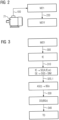
- the Figure 1 shows a section of a railway track 10, which is equipped with a railway switch 20.
- a railway switch drive 21 of the railway switch 20 is used a monitoring device 30 monitors the occurrence of possible errors.
- the monitoring device 30 has a recording device 31 which records the actual operating noises BG of the railway switch drive 21 during the switch changing processes and generates corresponding acoustic operating noise measurements M (BG). With the operating noise measurements M(BG), it can also form an operating noise data set DS(BGm) for each switch circuit.
- the operating noise measurements M(BG) or the operating noise data sets DS(BGm) can also be referred to as real operating noise measurements and real operating noise data sets due to their relationship to the real world.
- the recording device 31 preferably includes one or more microphones.
- the monitoring device 30 is equipped with an analysis device 32, which has been trained on the basis of training data TD and is based on artificial intelligence.
- the artificial intelligence of the analysis device 32 can be based on a neural network, for example.
- the analysis device 32 is suitable or designed to detect an actual occurrence of one or more errors for which training data TD has been created and the analysis device 32 has been trained, based on the real operating noises measured by the recording device 31. If one of the errors is detected, i.e. if a trained error actually occurs, a corresponding error signal FS is generated for this error.
- the trained analysis device 32 is used in the exemplary embodiment according to Figure 1 formed by a computing device 320 and a memory 321 in which a software program module SPM is stored
- the software program module SPM has been parameterized or trained through previous training in such a way that it can determine the occurrence of one or more trained errors based on the operating noises BG recorded by the recording device 31.
- the software program module SPM preferably contains the already mentioned trained neural network, which forms the basis for the artificial intelligence.
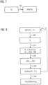
- a mechanical simulation module M21 is formed, which describes the mechanical properties of the railway switch drive 21 and allows a computer simulation of the operation of the railway switch drive 21.
- the mechanical simulation module M21 is preferably created on the basis of a finite element method FEM.
- a fictitious error is integrated into the mechanical simulation module M21 as part of an error addition step 220, which corresponds to an error in the railway switch drive 21 that can later be recognized in real operation.
- a fictitious mechanical simulation module M21f is formed by the error addition step 220.
- the fictitious error can, for example, be that a tooth is missing from a gear of the railway switch drive 21 or that it is virtually removed for the simulation, or that a part of the railway switch drive 21 has a crack or such a tooth is virtually added for the simulation.
- the fictitious mechanical simulation module M21f is used as part of a modal analysis step 300 (see Figure 3 ) the mechanical ones Natural frequencies fE of the railway switch drive 21 with the fictitious error are simulated.
- the Figure 4 shows an example of the natural frequencies fE determined as part of the modal analysis step 300 in the form of the amplitude A over the frequency f.
- the Figure 5 shows, as an example, the time course after an excitation over time t for one of the natural frequencies fE; the temporal decay of the amplitude A can be characterized by an attenuation value ⁇ .
- each of the calculated natural frequencies fE is assigned a virtual vibration element SE, the vibration behavior of which is defined by the respective natural frequency fE, a vibration amplitude A and a damping specification ⁇ .
- the vibration elements SE form a virtual overall oscillator system SGS, which describes the mechanical behavior of the railway switch drive 21 with regard to its noise emissions during operation, i.e. during the changeover processes.
- the virtual overall oscillator system SGS thus forms a simulation model SIM with which the drive operation of the railway switch drive 21 having the fictitious error can be simulated, with a view to the operating noises generated during operation.
- an excitation pulse I is fed into the overall oscillator system SGS, whereby the individual oscillation elements SE of the overall oscillator system SGS are set into vibration.
- an acoustic response signal AS(t) can be calculated, which describes the acoustic response to the simulated excitation pulse I in the time range or over time t.
- the Figure 6 shows an example of a typical acoustic response signal AS(t).
- the excitation pulse I clearly simulates the mechanical excitation that switching on an electric motor of the railway switch drive 21 would cause on the electric motor itself and the other components of the railway switch drive 21.
- the acoustic response signal AS(t) thus describes the (simulated) operating noises BGs of the railway switch drive 21 during its simulated operation in the faulty state.
- the acoustic response signal AS(t) is further processed, for example standardized, in order to create an operating noise data record DS(BGs). Since the operating noise data set DS(BGs) is based on the acoustic response signal AS(t) and thus on simulated operating noises BGs, it can also be referred to as a simulated operating noise data set.
- training data TD can be created, which is used to train and parameterize the analysis device 32 according to Figure 1 or whose software program module SPM can be used.
- the label step 340 is carried out, for example, with a view to using the training data TD for a support vector machine method.
- the Figure 7 shows by way of example the training of the analysis device 32 on the basis of the in Figure 3 shown training data TD to the trained analysis device 32 according to Figure 1 to build.
- the training can be carried out, for example, on the basis of a support vector machine method 700.
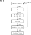
- the Figure 8 shows an exemplary embodiment of method steps with which simulated operating noise data sets DS (BGs) and corresponding training data TD can be automatically generated for a large number of fictitious errors that belong to the same type of error and only differ in one or more parameters.
- the crack depth can be integrated as an error parameter Prt in a mechanical simulation module M21f (Prt).
- Prt an error parameter
- This integration of the error parameter Prt makes it possible to automatically repeat steps 300 to 330 as part of one or more loop runs: For example, if steps 300 to 330 have been carried out for a first crack depth T1, i.e.
- both the crack depth as a parameter Prt and the crack width as a parameter Prb can be integrated into a mechanical simulation module M21f (Prt, Prb).
- Method steps 300 to 340 and 700 shown are preferably carried out by a training device 100, as exemplified in the Figure 10 is shown.
- the training device 100 is used in the exemplary embodiment according to Figure 10 formed by a computing device 110 and a memory 120.
- the memory 120 contains a modal analysis software module M300 for carrying out the modal analysis step 300, a synthesis software module M310 for carrying out the synthesis step 310, an excitation software module M320 for carrying out the excitation step 320, a further processing software module M330 for carrying out the further processing step 330, a label software module M330 for carrying out the label step 340 and a support vector machine software module M700 for carrying out the support vector machine method 700 is stored. If the computing device 110 executes the modules M300, M310, M320, M330, M340 and/or M700, it processes the corresponding method steps 300-340 or 700, as described above.
- the Figure 11 shows another section of the railway track 10, which is equipped with a railway barrier 20a.
- the railway barrier 20a has a railway barrier drive 21a, which is monitored for the occurrence of possible errors by means of a monitoring device 30a.
- the monitoring device 30a has a recording device 31a, which records the actual operating noise BG of the railway barrier drive 21a during the adjustment processes and generates corresponding acoustic operating noise measurement values M (BG). With the operating noise measurements M(BG), it can also form operating noise data sets DS(BGm).
- the monitoring device is equipped with an analysis device 32a.
- the analysis device 32a is used in the exemplary embodiment according to Figure 1 formed by a computing device 320a and a memory 321a in which a software program module SPMa is stored.
- the analysis device 32a can be connected to the analysis device 32 in accordance with the hardware Figure 1 be identical; Only the software program modules SPM and SPMa are different.
- the software program module SPMa has been parameterized or trained through previous training in such a way that it can detect the occurrence of one or more errors in the railway barrier drive 21a based on the operating noises BG recorded by the recording device 31a.
- the software program module SPMa preferably contains a trained neural network and forms artificial intelligence to detect such errors.
- the same method steps are preferably carried out as described above in connection with Figures 1 to 10 have been explained as an example for the railway switch 21.
- the training device 100 can be used according to Figure 10 be used, i.e. the same hardware as for training the analysis device 32 according to Figure 1 .
- the analysis devices 32 and 32a can be arranged locally in, on or near the electromechanical drive 21 or 21a to be monitored by them;
- the monitoring devices 30 and 30a can therefore be used locally as field devices Area of the electromechanical drives to be monitored can be arranged.
- the analysis devices 32 and 32a can also be integrated into or formed by remotely located computers or cloud computers, i.e. spatially separated from the recording devices 31 and 31a and the drives to be monitored;
- the monitoring devices 30 and 30a can alternatively also be formed by spatially distributed systems.
Landscapes
- Engineering & Computer Science (AREA)
- Mechanical Engineering (AREA)
- Health & Medical Sciences (AREA)
- Biomedical Technology (AREA)
- General Health & Medical Sciences (AREA)
- Train Traffic Observation, Control, And Security (AREA)
Priority Applications (1)
| Application Number | Priority Date | Filing Date | Title |
|---|---|---|---|
| EP22165868.5A EP4253190A1 (fr) | 2022-03-31 | 2022-03-31 | Dispositif de surveillance et procédé de paramétrage d'un dispositif de surveillance |
Applications Claiming Priority (1)
| Application Number | Priority Date | Filing Date | Title |
|---|---|---|---|
| EP22165868.5A EP4253190A1 (fr) | 2022-03-31 | 2022-03-31 | Dispositif de surveillance et procédé de paramétrage d'un dispositif de surveillance |
Publications (1)
| Publication Number | Publication Date |
|---|---|
| EP4253190A1 true EP4253190A1 (fr) | 2023-10-04 |
Family
ID=81388994
Family Applications (1)
| Application Number | Title | Priority Date | Filing Date |
|---|---|---|---|
| EP22165868.5A Pending EP4253190A1 (fr) | 2022-03-31 | 2022-03-31 | Dispositif de surveillance et procédé de paramétrage d'un dispositif de surveillance |
Country Status (1)
| Country | Link |
|---|---|
| EP (1) | EP4253190A1 (fr) |
-
2022
- 2022-03-31 EP EP22165868.5A patent/EP4253190A1/fr active Pending
Non-Patent Citations (3)
| Title |
|---|
| ATAMURADOV VEPA ET AL: "Railway Point Machine Prognostics Based on Feature Fusion and Health State Assessment", IEEE TRANSACTIONS ON INSTRUMENTATION AND MEASUREMENT, IEEE, USA, vol. 68, no. 8, 1 August 2019 (2019-08-01), pages 2691 - 2704, XP011734504, ISSN: 0018-9456, [retrieved on 20190711], DOI: 10.1109/TIM.2018.2869193 * |
| LEE JONGUK ET AL: "Fault Detection and Diagnosis of Railway Point Machines by Sound Analysis", vol. 16, no. 4, 16 April 2016 (2016-04-16), pages 549, XP055961629, Retrieved from the Internet <URL:https://www.ncbi.nlm.nih.gov/pmc/articles/PMC4851063/pdf/sensors-16-00549.pdf> [retrieved on 20220916], DOI: 10.3390/s16040549 * |
| SUN YONGKUI ET AL: "Condition Monitoring for Railway Point Machines Based on Sound Analysis and Support Vector Machine", CHINESE JOURNAL OF ELECTRONICS, TECHNOLOGY EXCHANGE LTD., HONG KONG, HK, vol. 29, no. 4, 1 July 2020 (2020-07-01), pages 786 - 792, XP006092477, ISSN: 1022-4653, DOI: 10.1049/CJE.2020.06.007 * |
Similar Documents
| Publication | Publication Date | Title |
|---|---|---|
| EP1933214A2 (fr) | Génération et adaptation automatisée d'un modèle de machine ou d'installation | |
| EP2685382B1 (fr) | Procédé et dispositif de création et de test d'un programme d'appareil de commande | |
| EP3786745B1 (fr) | Identification des écarts entre une installation réelle et son double numérique | |
| EP3499470B1 (fr) | Procédé de maintenance en fonction de l'état d'un dispositif d'accès | |
| DE102008010299A1 (de) | Verfahren zum Testen eines Mobilfunkgeräts | |
| EP3715982A1 (fr) | Capteur virtuel sur une plateforme pour machines supérieures | |
| DE102004058753A1 (de) | Verifizierung von Integrierte-Schaltung-Tests unter Verwendung einer Testsimulation und einer Integrierte-Schaltungs-Simulation mit einem simulierten Ausfall | |
| DE102016012451A1 (de) | Verfahren zum Überwachen, Analysieren und Betreiben wenigstens einer Produktionsanlage | |
| DE112021003677T5 (de) | Automatisierte unterstützte schaltkreisvalidierung | |
| EP3786746A1 (fr) | Analyse efficace d'erreurs au moyen des erreurs simulées dans un double numérique | |
| EP3546314A1 (fr) | Procédé et dispositif d'identification de défaillances pour un système technique | |
| EP1703350B1 (fr) | Diagnostic d'un système d'automatisation | |
| DE102017117322A1 (de) | Verfahren zur Herstellung eines Halbleiterbauelementes mittels computergestütztem Entwurf von Testszenarien | |
| DE112016007339T5 (de) | Simulationsvorrichtung | |
| EP1425564B1 (fr) | Procede et dispositif de diagnostic des vibrations resonantes d'un systeme mecatronique | |
| DE102020205131A1 (de) | Verfahren und Vorrichtung zum Simulieren eines technischen Systems | |
| EP4253190A1 (fr) | Dispositif de surveillance et procédé de paramétrage d'un dispositif de surveillance | |
| EP3714337B1 (fr) | Simulation de données de capteur modélisées de manière statistique | |
| EP3959498B1 (fr) | Analyse acoustique d'un état d'une machine | |
| DE19857462A1 (de) | Verfahren zur Prüfung von Einzelkomponenten eines Kraftfahrzeuges | |
| DE102011000958A1 (de) | Verfahren und System zum Testen von Software und/oder Hardware eines oder mehrerer in ein Kraftfahrzeug zu integrierender Bauteile | |
| WO2017029087A1 (fr) | Procédé de création automatique d'un modèle de processus et dispositif pour mettre en œuvre le procédé | |
| WO2017021211A1 (fr) | Simulateur de véhicule pour véhicule ferroviaire | |
| EP3553679A1 (fr) | Procédé de diagnostic de panne assisté par ordinateur pour un système technique | |
| WO1999038024A1 (fr) | Procede d'optimisation de specifications de controle et de minimisation de logiciels de controle assistees par ordinateur |
Legal Events
| Date | Code | Title | Description |
|---|---|---|---|
| PUAI | Public reference made under article 153(3) epc to a published international application that has entered the european phase |
Free format text: ORIGINAL CODE: 0009012 |
|
| STAA | Information on the status of an ep patent application or granted ep patent |
Free format text: STATUS: THE APPLICATION HAS BEEN PUBLISHED |
|
| AK | Designated contracting states |
Kind code of ref document: A1 Designated state(s): AL AT BE BG CH CY CZ DE DK EE ES FI FR GB GR HR HU IE IS IT LI LT LU LV MC MK MT NL NO PL PT RO RS SE SI SK SM TR |
|
| STAA | Information on the status of an ep patent application or granted ep patent |
Free format text: STATUS: REQUEST FOR EXAMINATION WAS MADE |
|
| 17P | Request for examination filed |
Effective date: 20231019 |
|
| RBV | Designated contracting states (corrected) |
Designated state(s): AL AT BE BG CH CY CZ DE DK EE ES FI FR GB GR HR HU IE IS IT LI LT LU LV MC MK MT NL NO PL PT RO RS SE SI SK SM TR |
|
| RAP3 | Party data changed (applicant data changed or rights of an application transferred) |
Owner name: SIEMENS MOBILITY GMBH |
|
| STAA | Information on the status of an ep patent application or granted ep patent |
Free format text: STATUS: EXAMINATION IS IN PROGRESS |
|
| 17Q | First examination report despatched |
Effective date: 20260206 |