EP4253248B1 - Propellerflugzeug - Google Patents
Propellerflugzeug Download PDFInfo
- Publication number
- EP4253248B1 EP4253248B1 EP23158653.8A EP23158653A EP4253248B1 EP 4253248 B1 EP4253248 B1 EP 4253248B1 EP 23158653 A EP23158653 A EP 23158653A EP 4253248 B1 EP4253248 B1 EP 4253248B1
- Authority
- EP
- European Patent Office
- Prior art keywords
- propeller
- electric machine
- aircraft
- electric
- engine
- Prior art date
- Legal status (The legal status is an assumption and is not a legal conclusion. Google has not performed a legal analysis and makes no representation as to the accuracy of the status listed.)
- Active
Links
Images


Classifications
-
- B—PERFORMING OPERATIONS; TRANSPORTING
- B64—AIRCRAFT; AVIATION; COSMONAUTICS
- B64D—EQUIPMENT FOR FITTING IN OR TO AIRCRAFT; FLIGHT SUITS; PARACHUTES; ARRANGEMENT OR MOUNTING OF POWER PLANTS OR PROPULSION TRANSMISSIONS IN AIRCRAFT
- B64D35/00—Transmitting power from power plants to propellers or rotors; Arrangements of transmissions
-
- B—PERFORMING OPERATIONS; TRANSPORTING
- B64—AIRCRAFT; AVIATION; COSMONAUTICS
- B64D—EQUIPMENT FOR FITTING IN OR TO AIRCRAFT; FLIGHT SUITS; PARACHUTES; ARRANGEMENT OR MOUNTING OF POWER PLANTS OR PROPULSION TRANSMISSIONS IN AIRCRAFT
- B64D27/00—Arrangement or mounting of power plants in aircraft; Aircraft characterised by the type or position of power plants
- B64D27/02—Aircraft characterised by the type or position of power plants
- B64D27/30—Aircraft characterised by electric power plants
- B64D27/31—Aircraft characterised by electric power plants within, or attached to, wings
-
- B—PERFORMING OPERATIONS; TRANSPORTING
- B64—AIRCRAFT; AVIATION; COSMONAUTICS
- B64D—EQUIPMENT FOR FITTING IN OR TO AIRCRAFT; FLIGHT SUITS; PARACHUTES; ARRANGEMENT OR MOUNTING OF POWER PLANTS OR PROPULSION TRANSMISSIONS IN AIRCRAFT
- B64D27/00—Arrangement or mounting of power plants in aircraft; Aircraft characterised by the type or position of power plants
- B64D27/02—Aircraft characterised by the type or position of power plants
- B64D27/30—Aircraft characterised by electric power plants
- B64D27/32—Aircraft characterised by electric power plants within, or attached to, fuselages
-
- B—PERFORMING OPERATIONS; TRANSPORTING
- B64—AIRCRAFT; AVIATION; COSMONAUTICS
- B64D—EQUIPMENT FOR FITTING IN OR TO AIRCRAFT; FLIGHT SUITS; PARACHUTES; ARRANGEMENT OR MOUNTING OF POWER PLANTS OR PROPULSION TRANSMISSIONS IN AIRCRAFT
- B64D27/00—Arrangement or mounting of power plants in aircraft; Aircraft characterised by the type or position of power plants
- B64D27/02—Aircraft characterised by the type or position of power plants
- B64D27/30—Aircraft characterised by electric power plants
- B64D27/33—Hybrid electric aircraft
-
- B—PERFORMING OPERATIONS; TRANSPORTING
- B64—AIRCRAFT; AVIATION; COSMONAUTICS
- B64D—EQUIPMENT FOR FITTING IN OR TO AIRCRAFT; FLIGHT SUITS; PARACHUTES; ARRANGEMENT OR MOUNTING OF POWER PLANTS OR PROPULSION TRANSMISSIONS IN AIRCRAFT
- B64D27/00—Arrangement or mounting of power plants in aircraft; Aircraft characterised by the type or position of power plants
- B64D27/02—Aircraft characterised by the type or position of power plants
- B64D27/30—Aircraft characterised by electric power plants
- B64D27/35—Arrangements for on-board electric energy production, distribution, recovery or storage
-
- B—PERFORMING OPERATIONS; TRANSPORTING
- B64—AIRCRAFT; AVIATION; COSMONAUTICS
- B64D—EQUIPMENT FOR FITTING IN OR TO AIRCRAFT; FLIGHT SUITS; PARACHUTES; ARRANGEMENT OR MOUNTING OF POWER PLANTS OR PROPULSION TRANSMISSIONS IN AIRCRAFT
- B64D2221/00—Electric power distribution systems onboard aircraft
-
- Y—GENERAL TAGGING OF NEW TECHNOLOGICAL DEVELOPMENTS; GENERAL TAGGING OF CROSS-SECTIONAL TECHNOLOGIES SPANNING OVER SEVERAL SECTIONS OF THE IPC; TECHNICAL SUBJECTS COVERED BY FORMER USPC CROSS-REFERENCE ART COLLECTIONS [XRACs] AND DIGESTS
- Y02—TECHNOLOGIES OR APPLICATIONS FOR MITIGATION OR ADAPTATION AGAINST CLIMATE CHANGE
- Y02T—CLIMATE CHANGE MITIGATION TECHNOLOGIES RELATED TO TRANSPORTATION
- Y02T50/00—Aeronautics or air transport
- Y02T50/60—Efficient propulsion technologies, e.g. for aircraft
Definitions
- the present invention relates to a propeller-driven aircraft.
- An aircraft may comprise two propellers carried by two wings arranged transversely on either side of an airframe.
- the two propellers may be rotated independently by two respective heat engines.
- the term heat engine refers to an engine operating using fuel, such as for example a piston engine, a turboprop sometimes called a "turboprop" or a free turbine turboshaft engine.
- Another example of an aircraft includes two propellers mounted head-to-tail in a configuration sometimes referred to as a "push-pull" configuration.
- the seaplane known under the trademark “SeaStar®” has two head-to-tail propellers driven by two engines arranged in a common nacelle offset above a wing.
- the two propellers are substantially aligned on an axis parallel to a longitudinal direction of the aircraft.
- the efficiency of an engine can be assessed through its specific fuel consumption, sometimes called “specific fuel consumption” in English.
- the specific fuel consumption of an engine quantifies the energy efficiency of an engine in relation to the power developed by the engine.
- the specific fuel consumption of an engine, and in particular of a turboshaft or turboprop engine, tends to decrease with an increase in the power developed by this engine, at least as long as the power developed is below a high threshold.
- each engine can be sized to ensure flight in the event of failure of the other engine. Therefore, in normal operating conditions, the engines each develop a power lower than the maximum power that can be developed and more simply called "maximum power". For example, the power required for flight can be distributed equally between the propellers in cruising flight and each engine can develop a power substantially equal to half of its maximum power. Consequently, the specific consumption of each of the engines is then not optimized.
- the present invention then aims to propose an aircraft according to claim 1.
- the electrical energy transmission chain may include at least one electrical energy storage device, possibly rechargeable.
- Such an electrical energy storage device may comprise at least one electric battery, a cell, an accumulator, etc.
- the electrical energy storage device may be rechargeable, for example to enable the storage of electrical energy produced by the first electrical machine or a separate electrical generator.
- the electrical energy storage device may electrically power a starter if necessary, or may also electrically power the first electrical machine and/or the second electrical machine or even another electric motor if necessary.
- the aircraft may include a rudder connected to an actuator, said actuator being configured to deflect said rudder into a predetermined position in the flight phase at specific consumption optimized to counter a yaw moment generated on the aircraft by the rotating first propeller.
- the aircraft 1 comprises a cell 2 which extends longitudinally from a nose 3 to a tail 4.
- the tail 4 may comprise a rudder 7, optionally movable by an actuator 8 and/or flight controls.
- the rudder 7 may be fully movable or may comprise one or more flaps which are movable relative to at least one fixed rudder surface.
- the aircraft 1 further comprises wings 5, 6 which are arranged transversely on either side of the cell 2.
- the wings 5, 6 may jointly form a continuous or discontinuous wing.
- the aircraft 1 comprises a first propeller 11 and a second propeller 12.
- first propeller 11 and the second propeller 12 are arranged respectively on the first wing 5 and the second wing 6.
- the first propeller 11 and the second propeller 12 may be arranged head to tail.
- the first propeller 11 and the second propeller 12 may be counter-rotating and/or arranged above the cell 2 and/or rotated along the same axis of rotation.
- the aircraft 1 comprises a feathering device for at least one propeller 11, 12, such as for example a clutch 90.
- the first propeller 11 and the second propeller 12 may be different, having different diameters and/or numbers of blades, or identical.
- the aircraft 1 comprises an installation 20 for rotating the first propeller 11 and the second propeller 12 around their respective axes of rotation.
- This installation 20 comprises a first heat engine 21 cooperating with a first electric machine 31 to rotate the first propeller 11.
- a second electric machine 32 is configured to rotate the second propeller 12, in cooperation with a second heat engine 22.
- the first heat engine 21 and the second heat engine 22 comprise a free turbine turboshaft engine.
- the aircraft 1 therefore comprises at least one fuel tank 25 supplying fuel to the first thermal engine 21 and the second thermal engine 22, if applicable.
- the first heat engine 21 and the second heat engine 22, if any, may be identical or different.
- the first electric machine 31 and the second electric machine 32 can optionally serve as a starter for the heat engine(s) 21, 22.
- the first heat engine 21 and the second heat engine 22 may comprise an engine computer.
- the engine computer may in particular be configured to control a fuel metering device according to a received control signal.
- a computer is a processing unit that may include, for example, at least one processor and at least one memory, at least one integrated circuit, at least one programmable system, at least one logic circuit, these examples not limiting the scope given to the expression "processing unit".
- the term processor may also designate a central processing unit known by the acronym CPU, a graphics processing unit GPU, a digital unit known by the acronym DSP, a microcontroller, etc.
- the first electrical machine 31 and the second electrical machine 32 are configured to be able to operate in electric motor mode or in electric generator mode.
- the aircraft 1 is provided with an electrical energy transmission chain 35 which electrically connects the first electrical machine 31 and the second electrical machine 32.
- the electrical energy transmission chain 35 comprises one or more electrical connections 37.
- the electrical energy transmission chain 35 may comprise at least one electrical energy storage member 36, possibly rechargeable.
- an electrical energy storage member 36 may for example comprise an electric cell, an electric battery, an electric accumulator.
- the aircraft 1 can operate according to a flight phase with optimized specific consumption.
- the thermal engines 21, 22 and the electric machines 31, 32 are piloted to achieve such a flight phase with optimized specific consumption.
- the aircraft 1 comprises a human-machine interface 51 for implementing the consumption flight phase specific optimized, for example of the button, lever, touch screen or other type.
- the human-machine interface 51 emits a control signal carrying an order to implement the flight phase with optimized specific consumption.
- This control signal can be transmitted to one or more thermal engines 21, 22 and to the electrical machines 31, 32 or to a computer of the aircraft 1.
- the aircraft 1 may comprise a flight computer 52 in communication with sensors 53 to automatically implement the flight phase with optimized specific consumption under predetermined conditions.
- the flight computer 52 is in wired or wireless connection with the thermal engine(s) 21, 22 and the electrical machines 31, 32.
- the flight computer 52 is configured to transmit control signals requiring a particular operating mode to the thermal engine(s) 21, 22 and the electrical machines 31, 32.
- the flight computer 52 can store one or more piloting laws to generate the control signals.
- a control signal transmitted to a heat engine may carry a power to be developed by the heat engine and/or a fuel supply flow rate.
- the control signal carries a power setpoint, the fuel flow rate being controlled by an engine computer to correspond to the power setpoint, the propeller pitch possibly being adapted in a usual manner to consume the power transmitted at the targeted speed.
- a control signal transmitted to an electric machine may carry an operating order in engine mode or in electric generator mode.
- the first heat engine 21 and the first electric machine 31 are mechanically connected to a first power transmission chain 41.
- the first power transmission chain 41 may comprise at least one shaft, at least one freewheel, at least one clutch, at least one conjugate wheel, etc.
- the first power transmission chain 41 may comprise a first input connected to a power shaft of the first heat engine 21, as well as a second input connected to the first electric machine 31, and an output connected to the first propeller 11.
- the first power transmission chain 41 may comprise a conjugation wheel kinematically connected to the first input, to the second input and to the first propeller 11.
- a freewheel or a clutch may be interposed between the conjugation wheel and the first heat engine 21.
- the first electric machine 31 is then a machine that can operate in electric motor mode or in electric generator mode.
- the first electric machine 31 is configured to operate in electric generator mode during a flight phase with optimized specific consumption.
- the aircraft 1 comprises a second heat engine 22 connected to a second power transmission chain 42 rotating the second propeller 12.
- the second power transmission chain 42 may comprise at least one shaft, at least one freewheel, at least one clutch, at least one conjugate wheel, etc.
- the second power transmission chain 42 may comprise a first input connected to a power shaft of the second heat engine 22, as well as a second input mechanically connected to the second electric machine 32, and an output connected to the second propeller 12.
- the second power transmission chain 42 may comprise a conjugation wheel kinematically connected to the first input, to the second input and to the second propeller 12.
- a freewheel or a clutch may be interposed between the conjugation wheel and the second heat engine 22.
- the second electric machine 32 is then a machine capable of operating in electric motor mode or in electric generator mode.
- the second electric machine 32 is configured to operate in electric motor mode during a flight phase with optimized specific consumption.
- each heat engine 21,22 can form the first heat engine 21 or the second heat engine 22 and each electric machine 31,32 can form the first electric machine 31 or the second electric machine 32.
- the first heat engine 21 when a flight phase with optimized specific consumption is implemented, on the order of an interface or a flight computer for example, the first heat engine 21 is controlled by its engine computer to develop a power, for example predetermined, high or even close to its maximum power. The first heat engine 21 then sets in motion the moving parts, shafts and gears in particular, of the first power transmission chain 41. The first propeller 11 is thus set in rotation.
- the first electric machine 31 is driven to operate in electric generator mode.
- the first electric machine 31 is set in motion by the first chain of power transmission 41 for generating electrical energy injected into the electrical energy transmission chain 35.
- the second heat engine 22 is stopped or slowed down.
- the second electric machine 32 is controlled to operate in electric motor mode.
- the second electric machine 32 sets the second propeller 12 in motion by the second power transmission chain 42 from the electrical energy supplied by the electrical energy transmission chain 35.
- a freewheel of the second power transmission chain 42 kinematically disconnects the second propeller 12 from the second heat engine 22.
- the first heat engine 11 develops a maximum power Pmax and the second heat engine 12 develops zero power. Substantially half of this maximum power is used so that the first propeller 11 then develops a first thrust T1. The other half of this maximum power is used to generate electrical energy with the first electric machine 31. This electrical energy can in whole or in part electrically power the second electric machine 32 which sets the second propeller 12 in motion to produce a second thrust T2 substantially equal to the first thrust T1.
- thermal engines instead of having two thermal engines each developing a power of around half their maximum power, one thermal engine is stopped or idling and the other thermal engine develops a power close to its maximum power. This results in an optimization of the specific consumption of thermal engines.
- the second electric machine 32 has an operating mode as an electric motor.
- This second electric machine 32 is mechanically connected to the second propeller 12, directly or via a second power transmission chain, the second electric machine 32 receiving electrical energy from the electrical energy transmission chain 35.
- the aircraft has a single heat engine for driving the propellers.
- an electrical energy storage member 36 may transiently supply electrical power to the first electrical machine 11 and/or to the second electrical machine 12, for example in the event of a breakdown of the first thermal engine 21.
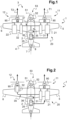
- FIG. 3 illustrates a second alternative aircraft according to the invention.
- the first heat engine 21 may be mechanically connected to the first electric machine 31, the first electric machine 31 being able to operate in electric motor mode or in electric generator mode.
- the first electric machine 21 comprises a shaft connected to a shaft of a gas generator of the first heat engine 11, like a usual generator-starter of a turbo engine.
- a second heat engine 22 is mechanically connected to the second electric machine 32, the second electric machine 32 capable of operating in electric motor mode or in electric generator mode.
- the second electric machine 22 comprises a shaft connected to a shaft of a gas generator of the second heat engine 21, like a conventional generator-starter of a turbo engine.
- each heat engine 21,22 can develop power transmitted independently to the respective propeller 11,12.
- the second propeller 12 is feathered by its feathering device 90.
- a clutch present between the second propeller 12 and the second thermal engine 22 is disengaged.
- the first heat engine 21 develops power to rotate the first propeller 11. As a result, the first heat engine 21 develops power close to its maximum power while the second heat engine 22 is stopped or idling.
- the possible actuator 8 can move the drift 7 into a predetermined position to counteract a yaw moment generated on the cell 2 by the rotation of the first propeller 11.
- FIG. 4 illustrates a third alternative aircraft which does not fall within the scope of the claims.
- the first propeller 11 and the second propeller 12 are arranged head-to-tail in a "push-pull" configuration.
- the installation 20 is arranged at least partly in a nacelle 13 present above the cell 2.
- the first electric machine 31 is configured to operate at least in electric motor mode, or even only in electric motor mode.
- the electrical connections are illustrated in broken lines, the mechanical connections in continuous lines.
- the first electric machine 31 is mechanically connected to the first propeller 11 directly or indirectly by a first power transmission chain.
- the second electric machine 32 is configured to operate at least in electric motor mode, or even only in electric motor mode.
- the second electric machine 32 is mechanically connected to the second propeller 12 directly or indirectly by a second power transmission chain.
- the electrical energy transmission chain 35 further comprises at least one electrical energy generator 38, 39 cooperating with at least one heat engine 21 or 22.
- the first heat engine 21 is connected to a first electric energy generator 38 of the electric energy transmission chain 35.
- a second heat engine 22 is connected to a second electric energy generator 39 of the electric energy transmission chain 35.
- each heat engine 21, 22 can develop power transmitted independently to the electric energy generator 38, 39. respective.
- the electric machines 31, 32 independently rotate the respective propellers 11, 12.
- the second thermal engine 22 is stopped or idling while the first thermal engine 21 develops a high power to electrically power the first electric machine 31 and the second electric machine 32. Consequently, the first thermal engine 21 develops a power close to its maximum power while the second thermal engine 22 is stopped or idling.
- the first heat engine 21 is connected to a second electric energy generator 39 of the electric energy transmission chain 35.
- the first electric machine 31 is configured to operate in electric motor and electric generator mode.
- the electrical connections are illustrated in broken lines, the mechanical connections in continuous lines.
- first electric machine 31 and the first heat engine 21 are mechanically connected to a first power transmission chain 41, for example of the type described above, rotating the first propeller 11.
- the second electric machine 32 is configured to operate in electric motor and electric generator mode.
- the second electric machine 32 is mechanically connected to a second transmission chain of power 42, for example of the type described above, rotating the second propeller 12.
- a second heat engine 22 is connected to the second power transmission chain 42.
- each heat engine 21, 22 can develop power transmitted independently to the respective propeller 11, 12.
- the electrical machines 31, 32 can be inactive or can operate in engine or even electric generator mode.
- the second thermal engine 22 is stopped or idling while the first thermal engine 21 develops high power to drive the first propeller 11 and to set in motion the first electric machine 31 which operates in electric generator mode. Conversely, the second electric machine 32 operates in electric motor mode.
- the first heat engine 21 is connected to the first power transmission chain 41 and to the second power transmission chain 42.
Landscapes
- Engineering & Computer Science (AREA)
- Aviation & Aerospace Engineering (AREA)
- Mechanical Engineering (AREA)
- Engine Equipment That Uses Special Cycles (AREA)
- Transmission Devices (AREA)
Claims (3)
- Flugzeug (1) mit einem ersten Propeller (11) und einem zweiten Propeller (12), wobei das Flugzeug (1) einen ersten Verbrennungsmotor (21) sowie eine erste elektrische Maschine (31) umfasst, die konfiguriert sind, um den ersten Propeller (11) in Drehung zu versetzen, wobei das Flugzeug (1) mindestens eine zweite elektrische Maschine (32) umfasst, die konfiguriert ist, um den zweiten Propeller (12) in Drehung zu versetzen, wobei das Flugzeug (1) eine elektrische Energieübertragungskette (35) aufweist, die die erste elektrische Maschine (31) und die zweite elektrische Maschine (32) elektrisch verbindet, wobei der erste Verbrennungsmotor (21) mechanisch mit der ersten elektrischen Maschine (31) verbunden ist, wobei der erste Verbrennungsmotor (21) ein Gasturbinentriebwerk mit freier Turbine ist, das einen Gasgenerator umfasst, wobei die erste elektrische Maschine (31) eine Welle aufweist, die mit einer Welle des Gasgenerators des ersten Verbrennungsmotors (21) verbunden ist, wobei die erste elektrische Maschine (31) im Elektromotor-Modus oder im Stromgenerator-Modus betreibbar ist, die zweite elektrische Maschine (32) im Elektromotor-Modus oder im Stromgenerator-Modus betreibbar ist, die zweite elektrische Maschine (32) mit einem zweiten Verbrennungsmotor (22) verbunden ist, der zweite Verbrennungsmotor (22) ein Gasturbinentriebwerk mit freier Turbine ist, das einen Gasgenerator umfasst, die zweite elektrische Maschine (32) eine Welle aufweist, die mit einer Welle des Gasgenerators des zweiten Verbrennungsmotors (22) verbunden ist, der zweite Verbrennungsmotor (22) mit dem zweiten Propeller (12) verbunden ist, und das Flugzeug eine Vorrichtung zum Versetzen des zweiten Propellers in Segelstellung aufweist, so dass während einer Flugphase mit optimiertem spezifischen Verbrauch der erste Verbrennungsmotor (21) konfiguriert ist, um den ersten Propeller (11) in Drehung zu versetzen, und die Vorrichtung zum Versetzen in Segelstellung konfiguriert ist, um den zweiten Propeller in Segelstellung zu versetzen.
- Flugzeug nach Anspruch 1,
bei dem die elektrische Energieübertragungskette (35) mindestens ein Speicherorgan für elektrische Energie (36) umfasst. - Flugzeug nach einem der Ansprüche 1 bis 2,
wobei das Flugzeug (1) ein Seitenleitwerk (7) umfasst, das mit einem Aktuator (8) verbunden ist, wobei der Aktuator (8) konfiguriert ist, um das Seitenleitwerk (7) in der Flugphase mit optimiertem spezifischem Verbrauch in eine vorgegebene Position zu lenken, um einem an dem Flugzeug (1) durch den sich drehenden ersten Propeller (11) erzeugten Giermoment entgegenzuwirken.
Applications Claiming Priority (1)
| Application Number | Priority Date | Filing Date | Title |
|---|---|---|---|
| FR2202814A FR3134079A1 (fr) | 2022-03-29 | 2022-03-29 | Avion à hélices |
Publications (2)
| Publication Number | Publication Date |
|---|---|
| EP4253248A1 EP4253248A1 (de) | 2023-10-04 |
| EP4253248B1 true EP4253248B1 (de) | 2024-12-18 |
Family
ID=83188243
Family Applications (1)
| Application Number | Title | Priority Date | Filing Date |
|---|---|---|---|
| EP23158653.8A Active EP4253248B1 (de) | 2022-03-29 | 2023-02-25 | Propellerflugzeug |
Country Status (2)
| Country | Link |
|---|---|
| EP (1) | EP4253248B1 (de) |
| FR (1) | FR3134079A1 (de) |
Family Cites Families (6)
| Publication number | Priority date | Publication date | Assignee | Title |
|---|---|---|---|---|
| FR2949434B1 (fr) * | 2009-08-28 | 2011-10-07 | Benjamin Parzy | Aeronef comportant au moins deux groupes motopropulseurs electriques montes a l'arriere |
| US10676199B2 (en) * | 2017-06-12 | 2020-06-09 | General Electric Company | Propulsion system for an aircraft |
| US10981660B2 (en) * | 2018-04-19 | 2021-04-20 | The Boeing Company | Hybrid propulsion engines for aircraft |
| EP3980637B1 (de) * | 2019-06-07 | 2024-04-17 | Jetpel GmbH | Luftfahrzeug mit mantelpropellerantrieb |
| US11597514B2 (en) * | 2019-08-16 | 2023-03-07 | Embraer S.A. | Unmanned aircraft having reduced acoustic signatures |
| CA3101391A1 (en) * | 2019-12-03 | 2021-06-03 | United Technologies Advanced Projects, Inc. | Aircraft propulsion system and methods of feathering |
-
2022
- 2022-03-29 FR FR2202814A patent/FR3134079A1/fr active Pending
-
2023
- 2023-02-25 EP EP23158653.8A patent/EP4253248B1/de active Active
Also Published As
| Publication number | Publication date |
|---|---|
| FR3134079A1 (fr) | 2023-10-06 |
| EP4253248A1 (de) | 2023-10-04 |
Similar Documents
| Publication | Publication Date | Title |
|---|---|---|
| EP4259521B1 (de) | Hybrides antriebssystem für einen hubschrauber | |
| EP2631174B1 (de) | Drehflügelflugzeug, das mit einem Heckrotor ausgerüstet ist, und Verfahren zur Optimierung des Bertiebs eines Heckrotors | |
| EP2735512B1 (de) | Verfahren und hubschrauber mit drei triebwerken | |
| CN102971216B (zh) | 用于飞行器的混合动力驱动系统和能量系统 | |
| EP2524867B1 (de) | Verfahren zum Einspeisen für Motoren mit autonomem Antrieb eines Luftfahrzeug | |
| EP3787967B1 (de) | Antriebssystem für einen hubschrauber | |
| EP3995682B1 (de) | Verfahren zur steuerung einer triebwerksanlage eines drehflügelflugzeugs, die mindestens zwei turbotriebwerke umfasst | |
| EP3912909B1 (de) | Verfahren zur optimierung des von einem drehflügelflugzeug am boden erzeugten lärms | |
| EP3967598B1 (de) | Verfahren und vorrichtung zur verwaltung der energie, die von einer hybrid-triebwerksanlage für drehflügelflugzeuge geliefert wird | |
| US8159081B2 (en) | Controlling propeller rotor overspeed | |
| EP3031730B1 (de) | Luftfahrzeug und Verfahren zur Ausstattung eines solchen Luftfahrzeugs | |
| EP3889048A1 (de) | Verfahren zur optimierung des lärms, der von einem drehflügelflugzeug im flug erzeugt wird | |
| EP3546366B1 (de) | Propellerantriebseinheit, die einen verbrennungsmotor und einen elektromotor umfasst, sowie eine solche propellerantriebseinheit umfassendes luftfahrzeug | |
| EP3976474B1 (de) | Motor mit hybrider antriebseinheit und entsprechendem kontrollverfahren | |
| EP3883854B1 (de) | Antriebssystem eines flugzeugs und verfahren zum betreiben eines solchen systems | |
| US20240113513A1 (en) | Overspeed and/or overtorque protection for hybrid electric aircraft propulsion system | |
| CA3202419A1 (fr) | Dirigeable equipe d'un systeme de propulsion distribuee electrique | |
| EP4046909A1 (de) | Verfahren und vorrichtung zur steuerung einer thermischen und elektrischen antriebsanlage für drehflügelflugzeuge | |
| EP4310001B1 (de) | Flugzeug mit mindestens zwei triebwerken und einer vorrichtung, die zur verbindung mit einem turbomotor konfiguriert ist, und verfahren zur steuerung eines solchen flugzeugs | |
| EP4253248B1 (de) | Propellerflugzeug | |
| EP3828082B1 (de) | Hybrid-drehflügelflugzeug mit mindestens einem propeller in pusher- oder tractor-konfiguration, und entsprechendes steuerungsverfahren | |
| EP2620370B1 (de) | Notstromerzeugungsaggregat für ein Luftfahrzeug, Luftfahrzeug und entsprechendes Verfahren | |
| FR2976555A1 (fr) | Recuperation d'energie electrique sur une helice d'aeronef | |
| EP4448384A1 (de) | Verfahren zur drehzahlregelung eines antriebs für ein hybridtriebwerk bei ausfall des hauptregelungssystems des hybridantriebs | |
| FR3135249A1 (fr) | Procédé de fonctionnement d’un ensemble propulsif pour un aéronef |
Legal Events
| Date | Code | Title | Description |
|---|---|---|---|
| PUAI | Public reference made under article 153(3) epc to a published international application that has entered the european phase |
Free format text: ORIGINAL CODE: 0009012 |
|
| STAA | Information on the status of an ep patent application or granted ep patent |
Free format text: STATUS: THE APPLICATION HAS BEEN PUBLISHED |
|
| AK | Designated contracting states |
Kind code of ref document: A1 Designated state(s): AL AT BE BG CH CY CZ DE DK EE ES FI FR GB GR HR HU IE IS IT LI LT LU LV MC ME MK MT NL NO PL PT RO RS SE SI SK SM TR |
|
| STAA | Information on the status of an ep patent application or granted ep patent |
Free format text: STATUS: REQUEST FOR EXAMINATION WAS MADE |
|
| 17P | Request for examination filed |
Effective date: 20231124 |
|
| P01 | Opt-out of the competence of the unified patent court (upc) registered |
Effective date: 20231124 |
|
| RBV | Designated contracting states (corrected) |
Designated state(s): AL AT BE BG CH CY CZ DE DK EE ES FI FR GB GR HR HU IE IS IT LI LT LU LV MC ME MK MT NL NO PL PT RO RS SE SI SK SM TR |
|
| GRAP | Despatch of communication of intention to grant a patent |
Free format text: ORIGINAL CODE: EPIDOSNIGR1 |
|
| STAA | Information on the status of an ep patent application or granted ep patent |
Free format text: STATUS: GRANT OF PATENT IS INTENDED |
|
| RIC1 | Information provided on ipc code assigned before grant |
Ipc: B64D 27/02 20060101ALN20240911BHEP Ipc: B64D 35/00 20060101ALI20240911BHEP Ipc: B64D 27/24 20060101AFI20240911BHEP |
|
| INTG | Intention to grant announced |
Effective date: 20240926 |
|
| GRAS | Grant fee paid |
Free format text: ORIGINAL CODE: EPIDOSNIGR3 |
|
| GRAA | (expected) grant |
Free format text: ORIGINAL CODE: 0009210 |
|
| STAA | Information on the status of an ep patent application or granted ep patent |
Free format text: STATUS: THE PATENT HAS BEEN GRANTED |
|
| AK | Designated contracting states |
Kind code of ref document: B1 Designated state(s): AL AT BE BG CH CY CZ DE DK EE ES FI FR GB GR HR HU IE IS IT LI LT LU LV MC ME MK MT NL NO PL PT RO RS SE SI SK SM TR |
|
| REG | Reference to a national code |
Ref country code: CH Ref legal event code: EP |
|
| REG | Reference to a national code |
Ref country code: DE Ref legal event code: R096 Ref document number: 602023001361 Country of ref document: DE |
|
| REG | Reference to a national code |
Ref country code: IE Ref legal event code: FG4D Free format text: LANGUAGE OF EP DOCUMENT: FRENCH |
|
| REG | Reference to a national code |
Ref country code: LT Ref legal event code: MG9D |
|
| PG25 | Lapsed in a contracting state [announced via postgrant information from national office to epo] |
Ref country code: HR Free format text: LAPSE BECAUSE OF FAILURE TO SUBMIT A TRANSLATION OF THE DESCRIPTION OR TO PAY THE FEE WITHIN THE PRESCRIBED TIME-LIMIT Effective date: 20241218 |
|
| PG25 | Lapsed in a contracting state [announced via postgrant information from national office to epo] |
Ref country code: FI Free format text: LAPSE BECAUSE OF FAILURE TO SUBMIT A TRANSLATION OF THE DESCRIPTION OR TO PAY THE FEE WITHIN THE PRESCRIBED TIME-LIMIT Effective date: 20241218 |
|
| PG25 | Lapsed in a contracting state [announced via postgrant information from national office to epo] |
Ref country code: BG Free format text: LAPSE BECAUSE OF FAILURE TO SUBMIT A TRANSLATION OF THE DESCRIPTION OR TO PAY THE FEE WITHIN THE PRESCRIBED TIME-LIMIT Effective date: 20241218 |
|
| PG25 | Lapsed in a contracting state [announced via postgrant information from national office to epo] |
Ref country code: NO Free format text: LAPSE BECAUSE OF FAILURE TO SUBMIT A TRANSLATION OF THE DESCRIPTION OR TO PAY THE FEE WITHIN THE PRESCRIBED TIME-LIMIT Effective date: 20250318 |
|
| REG | Reference to a national code |
Ref country code: NL Ref legal event code: MP Effective date: 20241218 |
|
| PG25 | Lapsed in a contracting state [announced via postgrant information from national office to epo] |
Ref country code: LV Free format text: LAPSE BECAUSE OF FAILURE TO SUBMIT A TRANSLATION OF THE DESCRIPTION OR TO PAY THE FEE WITHIN THE PRESCRIBED TIME-LIMIT Effective date: 20241218 Ref country code: GR Free format text: LAPSE BECAUSE OF FAILURE TO SUBMIT A TRANSLATION OF THE DESCRIPTION OR TO PAY THE FEE WITHIN THE PRESCRIBED TIME-LIMIT Effective date: 20250319 |
|
| PG25 | Lapsed in a contracting state [announced via postgrant information from national office to epo] |
Ref country code: RS Free format text: LAPSE BECAUSE OF FAILURE TO SUBMIT A TRANSLATION OF THE DESCRIPTION OR TO PAY THE FEE WITHIN THE PRESCRIBED TIME-LIMIT Effective date: 20250318 |
|
| PG25 | Lapsed in a contracting state [announced via postgrant information from national office to epo] |
Ref country code: NL Free format text: LAPSE BECAUSE OF FAILURE TO SUBMIT A TRANSLATION OF THE DESCRIPTION OR TO PAY THE FEE WITHIN THE PRESCRIBED TIME-LIMIT Effective date: 20241218 |
|
| REG | Reference to a national code |
Ref country code: AT Ref legal event code: MK05 Ref document number: 1752073 Country of ref document: AT Kind code of ref document: T Effective date: 20241218 |
|
| PG25 | Lapsed in a contracting state [announced via postgrant information from national office to epo] |
Ref country code: SM Free format text: LAPSE BECAUSE OF FAILURE TO SUBMIT A TRANSLATION OF THE DESCRIPTION OR TO PAY THE FEE WITHIN THE PRESCRIBED TIME-LIMIT Effective date: 20241218 |
|
| PG25 | Lapsed in a contracting state [announced via postgrant information from national office to epo] |
Ref country code: PL Free format text: LAPSE BECAUSE OF FAILURE TO SUBMIT A TRANSLATION OF THE DESCRIPTION OR TO PAY THE FEE WITHIN THE PRESCRIBED TIME-LIMIT Effective date: 20241218 |
|
| PG25 | Lapsed in a contracting state [announced via postgrant information from national office to epo] |
Ref country code: ES Free format text: LAPSE BECAUSE OF FAILURE TO SUBMIT A TRANSLATION OF THE DESCRIPTION OR TO PAY THE FEE WITHIN THE PRESCRIBED TIME-LIMIT Effective date: 20241218 |
|
| PG25 | Lapsed in a contracting state [announced via postgrant information from national office to epo] |
Ref country code: IS Free format text: LAPSE BECAUSE OF FAILURE TO SUBMIT A TRANSLATION OF THE DESCRIPTION OR TO PAY THE FEE WITHIN THE PRESCRIBED TIME-LIMIT Effective date: 20250418 |
|
| PG25 | Lapsed in a contracting state [announced via postgrant information from national office to epo] |
Ref country code: PT Free format text: LAPSE BECAUSE OF FAILURE TO SUBMIT A TRANSLATION OF THE DESCRIPTION OR TO PAY THE FEE WITHIN THE PRESCRIBED TIME-LIMIT Effective date: 20250421 |
|
| PG25 | Lapsed in a contracting state [announced via postgrant information from national office to epo] |
Ref country code: EE Free format text: LAPSE BECAUSE OF FAILURE TO SUBMIT A TRANSLATION OF THE DESCRIPTION OR TO PAY THE FEE WITHIN THE PRESCRIBED TIME-LIMIT Effective date: 20241218 |
|
| PG25 | Lapsed in a contracting state [announced via postgrant information from national office to epo] |
Ref country code: RO Free format text: LAPSE BECAUSE OF FAILURE TO SUBMIT A TRANSLATION OF THE DESCRIPTION OR TO PAY THE FEE WITHIN THE PRESCRIBED TIME-LIMIT Effective date: 20241218 Ref country code: AT Free format text: LAPSE BECAUSE OF FAILURE TO SUBMIT A TRANSLATION OF THE DESCRIPTION OR TO PAY THE FEE WITHIN THE PRESCRIBED TIME-LIMIT Effective date: 20241218 |
|
| PG25 | Lapsed in a contracting state [announced via postgrant information from national office to epo] |
Ref country code: SK Free format text: LAPSE BECAUSE OF FAILURE TO SUBMIT A TRANSLATION OF THE DESCRIPTION OR TO PAY THE FEE WITHIN THE PRESCRIBED TIME-LIMIT Effective date: 20241218 |
|
| PG25 | Lapsed in a contracting state [announced via postgrant information from national office to epo] |
Ref country code: CZ Free format text: LAPSE BECAUSE OF FAILURE TO SUBMIT A TRANSLATION OF THE DESCRIPTION OR TO PAY THE FEE WITHIN THE PRESCRIBED TIME-LIMIT Effective date: 20241218 |
|
| PG25 | Lapsed in a contracting state [announced via postgrant information from national office to epo] |
Ref country code: SE Free format text: LAPSE BECAUSE OF FAILURE TO SUBMIT A TRANSLATION OF THE DESCRIPTION OR TO PAY THE FEE WITHIN THE PRESCRIBED TIME-LIMIT Effective date: 20241218 |
|
| PG25 | Lapsed in a contracting state [announced via postgrant information from national office to epo] |
Ref country code: MC Free format text: LAPSE BECAUSE OF FAILURE TO SUBMIT A TRANSLATION OF THE DESCRIPTION OR TO PAY THE FEE WITHIN THE PRESCRIBED TIME-LIMIT Effective date: 20241218 |
|
| REG | Reference to a national code |
Ref country code: DE Ref legal event code: R097 Ref document number: 602023001361 Country of ref document: DE |
|
| PG25 | Lapsed in a contracting state [announced via postgrant information from national office to epo] |
Ref country code: DK Free format text: LAPSE BECAUSE OF FAILURE TO SUBMIT A TRANSLATION OF THE DESCRIPTION OR TO PAY THE FEE WITHIN THE PRESCRIBED TIME-LIMIT Effective date: 20241218 |
|
| PG25 | Lapsed in a contracting state [announced via postgrant information from national office to epo] |
Ref country code: LU Free format text: LAPSE BECAUSE OF NON-PAYMENT OF DUE FEES Effective date: 20250225 |
|
| PLBE | No opposition filed within time limit |
Free format text: ORIGINAL CODE: 0009261 |
|
| STAA | Information on the status of an ep patent application or granted ep patent |
Free format text: STATUS: NO OPPOSITION FILED WITHIN TIME LIMIT |
|
| 26N | No opposition filed |
Effective date: 20250919 |
|
| REG | Reference to a national code |
Ref country code: BE Ref legal event code: MM Effective date: 20250228 |
|
| PG25 | Lapsed in a contracting state [announced via postgrant information from national office to epo] |
Ref country code: BE Free format text: LAPSE BECAUSE OF NON-PAYMENT OF DUE FEES Effective date: 20250228 |
|
| PG25 | Lapsed in a contracting state [announced via postgrant information from national office to epo] |
Ref country code: IE Free format text: LAPSE BECAUSE OF NON-PAYMENT OF DUE FEES Effective date: 20250225 |
|
| PGFP | Annual fee paid to national office [announced via postgrant information from national office to epo] |
Ref country code: DE Payment date: 20260218 Year of fee payment: 4 |
|
| PGFP | Annual fee paid to national office [announced via postgrant information from national office to epo] |
Ref country code: IT Payment date: 20260228 Year of fee payment: 4 |
|
| PGFP | Annual fee paid to national office [announced via postgrant information from national office to epo] |
Ref country code: FR Payment date: 20260219 Year of fee payment: 4 |