EP4253711A1 - Dispositif d'enroulement destiné à être utilisé sur un dispositif de protection solaire - Google Patents
Dispositif d'enroulement destiné à être utilisé sur un dispositif de protection solaire Download PDFInfo
- Publication number
- EP4253711A1 EP4253711A1 EP23160674.0A EP23160674A EP4253711A1 EP 4253711 A1 EP4253711 A1 EP 4253711A1 EP 23160674 A EP23160674 A EP 23160674A EP 4253711 A1 EP4253711 A1 EP 4253711A1
- Authority
- EP
- European Patent Office
- Prior art keywords
- support element
- winding device
- tension
- winding
- winding shaft
- Prior art date
- Legal status (The legal status is an assumption and is not a legal conclusion. Google has not performed a legal analysis and makes no representation as to the accuracy of the status listed.)
- Granted
Links
Images



Classifications
-
- E—FIXED CONSTRUCTIONS
- E06—DOORS, WINDOWS, SHUTTERS, OR ROLLER BLINDS IN GENERAL; LADDERS
- E06B—FIXED OR MOVABLE CLOSURES FOR OPENINGS IN BUILDINGS, VEHICLES, FENCES OR LIKE ENCLOSURES IN GENERAL, e.g. DOORS, WINDOWS, BLINDS, GATES
- E06B9/00—Screening or protective devices for wall or similar openings, with or without operating or securing mechanisms; Closures of similar construction
- E06B9/02—Shutters, movable grilles, or other safety closing devices, e.g. against burglary
- E06B9/08—Roll-type closures
- E06B9/11—Roller shutters
- E06B9/17—Parts or details of roller shutters, e.g. suspension devices, shutter boxes, wicket doors, ventilation openings
- E06B9/171—Rollers therefor; Fastening roller shutters to rollers
-
- E—FIXED CONSTRUCTIONS
- E06—DOORS, WINDOWS, SHUTTERS, OR ROLLER BLINDS IN GENERAL; LADDERS
- E06B—FIXED OR MOVABLE CLOSURES FOR OPENINGS IN BUILDINGS, VEHICLES, FENCES OR LIKE ENCLOSURES IN GENERAL, e.g. DOORS, WINDOWS, BLINDS, GATES
- E06B9/00—Screening or protective devices for wall or similar openings, with or without operating or securing mechanisms; Closures of similar construction
- E06B9/24—Screens or other constructions affording protection against light, especially against sunshine; Similar screens for privacy or appearance; Slat blinds
- E06B9/40—Roller blinds
- E06B9/42—Parts or details of roller blinds, e.g. suspension devices, blind boxes
- E06B9/44—Rollers therefor; Fastening roller blinds to rollers
Definitions
- the invention relates to a winding device for use on a sun protection device according to the preamble of claim 1.
- sun protection roller blinds the usually textile sun protection curtain is unwound vertically downwards in order to reduce solar radiation through a window.
- the sun protection curtain can be arranged either on the outside or on the inside of the window.
- the hollow winding shaft on which the sun protection curtain is wound will bend.
- this undesirable deflection is counteracted by using correspondingly stiff winding shafts.
- the disadvantage of these highly rigid winding shafts is that they are either very expensive to produce, for example made of carbon fiber reinforced plastic, or have a very high weight, for example with aluminum winding shafts.
- a support element is used, which is arranged inside the winding shaft and is mounted in a rotationally fixed manner on at least one longitudinal side.
- the winding shaft itself is rotatably mounted on this support element using pivot bearings.
- the support element is plastically deformed before being introduced into the winding shaft. Due to the plastic deflection of the support element achieved in this way, after the support element has been introduced into the winding shaft, the winding shaft is also deformed in the corresponding direction in order to thereby compensate for the deformation induced by the weight load. Due to the rotation-proof mounting of the support element, it is achieved that the deformation of the winding shaft induced by the deflection of the support element essentially acts vertically upwards and in this way counteracts the vertically downward, weight-induced deflection.
- the winding device is based on the basic idea that a tension or pressure element is provided on or in the non-rotatably mounted support element, which extends at least in sections outside the neutral bending fiber of the support element.
- the tension or pressure element can be clamped between two end pieces attached to the support element under tension or pressure. Due to the arrangement of the tension or compression element outside the neutral bending fiber, a supporting effect of the support element is induced by the clamping of the tension or compression element under tension or pressure. The supporting effect of the supporting element does not change due to the non-rotatable mounting of the supporting element even when the winding shaft rotates.
- the support element bends in a very specific direction, in particular vertically upwards, due to the tensile or compressive load by means of the tensile or compressive element.
- This vertically upward supporting effect of the support element can then compensate for the vertically downward deflection of the hollow winding shaft. Because the through the support effect induced by the tensile or compressive element only occurs when the tensile or compressive load is applied by clamping the tensile or compressive element between the support elements, the support element can be easily mounted in the hollow winding shaft. As a result, a load-free deflection of the support element does not occur.
- a push rod is used for this purpose.
- the tension or pressure element is designed in the manner of a push rod, it should preferably be arranged above the neutral bending fiber of the support element. As a result, it can be achieved that the downward, weight-induced deflection of the hollow winding shaft can be compensated for by the load-induced supporting effect of the supporting element.
- a pull rope can also be installed in the support element as a tension or pressure element.
- the extent of the weight-induced deflection of the hollow winding shaft in the winding device can be influenced by a variety of influencing variables.
- the length of the winding shaft and the weight of the sun protection curtain have a major influence on the amount of deflection.
- an adjusting element is provided between the at least one end piece on the support element on the one hand and the tension or pressure element on the other hand. The adjusting element serves to change the length of the tension or pressure element or the clamping length between the end bearings.
- the extent of the tensile or compressive load on the support element can be changed within a wide adjustment range, so that the support element bends correspondingly more or less.
- This vertically upward deflection of the support element then, depending on the setting, exactly compensates for the vertically downward, weight-induced deflection of the winding shaft, so that as a result both the winding shaft and the support element no longer have any geometric deflections, but rather have a largely vertical course.
- the adjusting element can be particularly simple in the form of an adjusting screw. This adjusting screw can then come into contact directly or indirectly on the end face of the push rod and induce a pressure load in the push rod by screwing in the adjusting screw.
- the support element has a polygonal cross section.
- the elastic deformation of the support element due to the tensile or compressive load can be particularly well adapted to the respective boundary conditions.
- a profile section is provided in which the tension or compression element is received.
- This profile section allows the tension or pressure element to be rotationally fixed Support element are stored so that it does not twist even under load, for example when adjusting the pressure using an adjusting screw.
- the support element is formed by a hollow profile, with an insertion profile being arranged inside the hollow profile.
- a profile section is then formed between the outside of the insertion profile and the inside of the hollow profile for receiving the tension or pressure element.
- This drive can in particular also be realized by means of a manually drivable drive element, for example a pull chain.
- a drive motor is arranged in the winding shaft next to the support element, with which the winding shaft can be driven in rotation.
- the winding device can be fastened between two wall fastening elements.
- the support element In order to mount the support element in a rotationally fixed manner, it can be connected in a simple manner to one of the two wall fastening elements in a rotationally fixed manner.
- the support element is axially resiliently mounted on at least one wall fastening element.
- the type of sun protection device for which the winding device according to the invention is used is basically arbitrary.
- winding device is particularly advantageous for sun protection roller blinds that are attached to the winding shaft of a sun protection curtain, which can be unwound vertically downwards by rotating the winding shaft.
- the winding device according to the invention can also be used in sun protection awnings in which the sun protection curtain is unrolled to the side.
- Fig. 1 shows a winding device 01 with a hollow winding shaft 02, on which an in Fig. 1 Sun protection curtain, not shown, can be wound up.
- the winding shaft 02 is rotatably mounted between two wall fastening elements 03 and 04 and can be moved by means of a drive motor 05 arranged inside the winding shaft 02 (see Fig. 3 ) are motor driven.
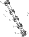
- Fig. 2 shows a support element 06 with a polygonal cross section, which is attached inside the hollow winding shaft 02 and can be connected in a rotationally fixed manner to the left wall fastening element 03.
- Several pivot bearings 07 are attached to the outer circumference of the support element 06 in which the hollow winding shaft 02 is rotatably mounted in order to realize a rotation of the winding shaft 02 relative to the non-rotatably attached support element 06.
- Fig. 3 shows the winding device 01 in longitudinal section. You can see the winding shaft 02, the wall fastening elements 03 and 04, the drive motor 05, the support element 06 and the pivot bearings 07.
- a pressure element 08 which is designed in the manner of a pressure rod, is arranged inside the support element 06.
- the pressure element 08 can be clamped under pressure between two end pieces 09 and 10, which are fixed inside the support element 06, in order in this way to induce an upward supporting effect of the support element.
- This supporting effect of the support element points vertically upwards and counteracts the weight-induced deflection of the winding shaft 02.
- the structure and function of the pressure element 08 are described below based on the illustration in Fig. 4 explained in more detail.
- Fig. 4 shows the longitudinal section through the winding device 01 in an enlarged section in the area of the wall fastening element 03.
- the pressure element 08 designed as a pressure rod, can be put under pressure using an adjusting screw 11. Due to the arrangement of the pressure element 08 outside the neutral bending fiber of the support element 06, the pressure load induces an upward supporting effect of the support element, which counteracts the weight-induced deflection of the winding shaft 02, so that the undesirable deflection is compensated for as a result.
- an insertion profile 12 is used, which is inserted into the support element 06 designed as a hollow profile.
- the wall fastening element 03 is arranged axially resiliently at the left end of the winding shaft 02 in order to achieve length compensation when fastening to the wall.
Landscapes
- Engineering & Computer Science (AREA)
- Structural Engineering (AREA)
- Architecture (AREA)
- Civil Engineering (AREA)
- Operating, Guiding And Securing Of Roll- Type Closing Members (AREA)
Applications Claiming Priority (1)
| Application Number | Priority Date | Filing Date | Title |
|---|---|---|---|
| DE102022106755.6A DE102022106755B4 (de) | 2022-03-23 | 2022-03-23 | Wickelvorrichtung zur Verwendung an einer Sonnenschutzeinrichtung |
Publications (3)
| Publication Number | Publication Date |
|---|---|
| EP4253711A1 true EP4253711A1 (fr) | 2023-10-04 |
| EP4253711C0 EP4253711C0 (fr) | 2025-05-21 |
| EP4253711B1 EP4253711B1 (fr) | 2025-05-21 |
Family
ID=85510950
Family Applications (1)
| Application Number | Title | Priority Date | Filing Date |
|---|---|---|---|
| EP23160674.0A Active EP4253711B1 (fr) | 2022-03-23 | 2023-03-08 | Dispositif d'enroulement destiné à être utilisé sur un dispositif de protection solaire |
Country Status (2)
| Country | Link |
|---|---|
| EP (1) | EP4253711B1 (fr) |
| DE (1) | DE102022106755B4 (fr) |
Citations (3)
| Publication number | Priority date | Publication date | Assignee | Title |
|---|---|---|---|---|
| FR1001329A (fr) * | 1946-04-17 | 1952-02-22 | Volet mécanique perfectionné de fermeture pour portes, devantures et toutes autresouvertures | |
| DE848700C (de) * | 1951-06-06 | 1952-09-08 | Duerener Metallwerke Aktien Ge | Stuetzaschse mit auf ihr drehbar angeordneten Federgehaeusen, die zum Auf- und Abwickeln eines Rolladens oder Rollgitters dienen |
| WO2020089220A1 (fr) | 2018-10-29 | 2020-05-07 | Bematech S.R.O. | Arbre de rouleau doté d'une armature |
Family Cites Families (2)
| Publication number | Priority date | Publication date | Assignee | Title |
|---|---|---|---|---|
| US1424572A (en) | 1920-09-27 | 1922-08-01 | King John Fielden | Awning-roller construction |
| FR1404122A (fr) | 1964-08-08 | 1965-06-25 | Avenard & Cie Ets | Rouleau moteur pour l'enroulement et le déroulement notamment de matériau souple tel qu'écran ou autres applications |
-
2022
- 2022-03-23 DE DE102022106755.6A patent/DE102022106755B4/de active Active
-
2023
- 2023-03-08 EP EP23160674.0A patent/EP4253711B1/fr active Active
Patent Citations (3)
| Publication number | Priority date | Publication date | Assignee | Title |
|---|---|---|---|---|
| FR1001329A (fr) * | 1946-04-17 | 1952-02-22 | Volet mécanique perfectionné de fermeture pour portes, devantures et toutes autresouvertures | |
| DE848700C (de) * | 1951-06-06 | 1952-09-08 | Duerener Metallwerke Aktien Ge | Stuetzaschse mit auf ihr drehbar angeordneten Federgehaeusen, die zum Auf- und Abwickeln eines Rolladens oder Rollgitters dienen |
| WO2020089220A1 (fr) | 2018-10-29 | 2020-05-07 | Bematech S.R.O. | Arbre de rouleau doté d'une armature |
Also Published As
| Publication number | Publication date |
|---|---|
| EP4253711C0 (fr) | 2025-05-21 |
| EP4253711B1 (fr) | 2025-05-21 |
| DE102022106755A1 (de) | 2023-09-28 |
| DE102022106755B4 (de) | 2024-02-08 |
Similar Documents
| Publication | Publication Date | Title |
|---|---|---|
| EP1525368B1 (fr) | Systeme de store | |
| EP2817471B1 (fr) | Dispositif d'enroulement et déroulement d'une bande de matière sur et à partir d'un arbre | |
| EP2452034B1 (fr) | Dispositif à enroulement pour l'occlusion d'ouvertures pratiquées dans des murs ou de fenêtres | |
| EP3354817B1 (fr) | Store comprenant des supports verticaux modifiables en longueur et palier coulissant latéral | |
| EP3508664B1 (fr) | Store à bras articulé pourvu de barre de compression | |
| EP1936105B1 (fr) | Pare-soleil vertical | |
| DE8703605U1 (de) | Rollo für Automobilfenster, insbesondere für PKW-Heckscheiben | |
| DE102022106755B4 (de) | Wickelvorrichtung zur Verwendung an einer Sonnenschutzeinrichtung | |
| EP3168410B1 (fr) | Pare-soleil vertical comprenant un profil d'extension ayant un poids supplémentaire | |
| EP2845962A1 (fr) | Marquise pour l'ombrage d'une section de sol | |
| DE4204640A1 (de) | Markise | |
| DE10161811C2 (de) | Gegenzugmarkise mit einseitigem Längenausgleich | |
| EP3633130A1 (fr) | Dispositif de traction doté d'un élément élastique réducteur de tension | |
| EP4382720A1 (fr) | Dispositif de rail de support d'un rail d'élément destiné à guider latéralement un élément de protection solaire afin d'empêcher l'entrée de lumière solaire dans un bâtiment | |
| EP4033047A1 (fr) | Installation de protection solaire doté d'un système de tirage | |
| DE69000703T2 (de) | Vorrichtung, um ein sonnenschirmtuch unter spannung zu halten, insbesondere fuer eine veranda oder pergola. | |
| DE20210855U1 (de) | Rollovorrichtung | |
| DE202004019844U1 (de) | Fensterrollo für ein Fahrzeugfenster | |
| DE19852686B4 (de) | Vorhang für eine nicht-rechteckige Fläche, insbesondere Fenster oder Öffnung | |
| CH673133A5 (en) | Sun blind operating drive - uses electrically operated drive wheels controlling drive chains for opposite ends of horizontal front bar | |
| AT522526B1 (de) | Schutzrollo | |
| DE10063454B4 (de) | Vorrichtung zum Verschließen und/oder Beschatten eines Öffnungsquerschnitts bzw. einer Fläche | |
| EP1936062B1 (fr) | Guidage d'un profilé d'extension | |
| EP1174564A2 (fr) | Store | |
| DE20315243U1 (de) | Montagehilfsvorrichtung für Sonnenschutzanlagen o.dgl. |
Legal Events
| Date | Code | Title | Description |
|---|---|---|---|
| PUAI | Public reference made under article 153(3) epc to a published international application that has entered the european phase |
Free format text: ORIGINAL CODE: 0009012 |
|
| STAA | Information on the status of an ep patent application or granted ep patent |
Free format text: STATUS: THE APPLICATION HAS BEEN PUBLISHED |
|
| AK | Designated contracting states |
Kind code of ref document: A1 Designated state(s): AL AT BE BG CH CY CZ DE DK EE ES FI FR GB GR HR HU IE IS IT LI LT LU LV MC ME MK MT NL NO PL PT RO RS SE SI SK SM TR |
|
| STAA | Information on the status of an ep patent application or granted ep patent |
Free format text: STATUS: REQUEST FOR EXAMINATION WAS MADE |
|
| 17P | Request for examination filed |
Effective date: 20240327 |
|
| RBV | Designated contracting states (corrected) |
Designated state(s): AL AT BE BG CH CY CZ DE DK EE ES FI FR GB GR HR HU IE IS IT LI LT LU LV MC ME MK MT NL NO PL PT RO RS SE SI SK SM TR |
|
| GRAP | Despatch of communication of intention to grant a patent |
Free format text: ORIGINAL CODE: EPIDOSNIGR1 |
|
| STAA | Information on the status of an ep patent application or granted ep patent |
Free format text: STATUS: GRANT OF PATENT IS INTENDED |
|
| RIC1 | Information provided on ipc code assigned before grant |
Ipc: E06B 9/44 20060101ALI20241220BHEP Ipc: E06B 9/171 20060101AFI20241220BHEP |
|
| INTG | Intention to grant announced |
Effective date: 20250109 |
|
| GRAS | Grant fee paid |
Free format text: ORIGINAL CODE: EPIDOSNIGR3 |
|
| GRAA | (expected) grant |
Free format text: ORIGINAL CODE: 0009210 |
|
| STAA | Information on the status of an ep patent application or granted ep patent |
Free format text: STATUS: THE PATENT HAS BEEN GRANTED |
|
| AK | Designated contracting states |
Kind code of ref document: B1 Designated state(s): AL AT BE BG CH CY CZ DE DK EE ES FI FR GB GR HR HU IE IS IT LI LT LU LV MC ME MK MT NL NO PL PT RO RS SE SI SK SM TR |
|
| REG | Reference to a national code |
Ref country code: GB Ref legal event code: FG4D Free format text: NOT ENGLISH |
|
| REG | Reference to a national code |
Ref country code: CH Ref legal event code: EP |
|
| REG | Reference to a national code |
Ref country code: DE Ref legal event code: R096 Ref document number: 502023001012 Country of ref document: DE |
|
| REG | Reference to a national code |
Ref country code: IE Ref legal event code: FG4D Free format text: LANGUAGE OF EP DOCUMENT: GERMAN |
|
| U01 | Request for unitary effect filed |
Effective date: 20250616 |
|
| U07 | Unitary effect registered |
Designated state(s): AT BE BG DE DK EE FI FR IT LT LU LV MT NL PT RO SE SI Effective date: 20250716 |
|
| PG25 | Lapsed in a contracting state [announced via postgrant information from national office to epo] |
Ref country code: ES Free format text: LAPSE BECAUSE OF FAILURE TO SUBMIT A TRANSLATION OF THE DESCRIPTION OR TO PAY THE FEE WITHIN THE PRESCRIBED TIME-LIMIT Effective date: 20250521 |
|
| PG25 | Lapsed in a contracting state [announced via postgrant information from national office to epo] |
Ref country code: GR Free format text: LAPSE BECAUSE OF FAILURE TO SUBMIT A TRANSLATION OF THE DESCRIPTION OR TO PAY THE FEE WITHIN THE PRESCRIBED TIME-LIMIT Effective date: 20250822 Ref country code: NO Free format text: LAPSE BECAUSE OF FAILURE TO SUBMIT A TRANSLATION OF THE DESCRIPTION OR TO PAY THE FEE WITHIN THE PRESCRIBED TIME-LIMIT Effective date: 20250821 |
|
| PG25 | Lapsed in a contracting state [announced via postgrant information from national office to epo] |
Ref country code: PL Free format text: LAPSE BECAUSE OF FAILURE TO SUBMIT A TRANSLATION OF THE DESCRIPTION OR TO PAY THE FEE WITHIN THE PRESCRIBED TIME-LIMIT Effective date: 20250521 |
|
| PG25 | Lapsed in a contracting state [announced via postgrant information from national office to epo] |
Ref country code: HR Free format text: LAPSE BECAUSE OF FAILURE TO SUBMIT A TRANSLATION OF THE DESCRIPTION OR TO PAY THE FEE WITHIN THE PRESCRIBED TIME-LIMIT Effective date: 20250521 |
|
| PG25 | Lapsed in a contracting state [announced via postgrant information from national office to epo] |
Ref country code: RS Free format text: LAPSE BECAUSE OF FAILURE TO SUBMIT A TRANSLATION OF THE DESCRIPTION OR TO PAY THE FEE WITHIN THE PRESCRIBED TIME-LIMIT Effective date: 20250821 |
|
| PG25 | Lapsed in a contracting state [announced via postgrant information from national office to epo] |
Ref country code: IS Free format text: LAPSE BECAUSE OF FAILURE TO SUBMIT A TRANSLATION OF THE DESCRIPTION OR TO PAY THE FEE WITHIN THE PRESCRIBED TIME-LIMIT Effective date: 20250921 |
|
| PG25 | Lapsed in a contracting state [announced via postgrant information from national office to epo] |
Ref country code: SM Free format text: LAPSE BECAUSE OF FAILURE TO SUBMIT A TRANSLATION OF THE DESCRIPTION OR TO PAY THE FEE WITHIN THE PRESCRIBED TIME-LIMIT Effective date: 20250521 |
|
| PG25 | Lapsed in a contracting state [announced via postgrant information from national office to epo] |
Ref country code: CZ Free format text: LAPSE BECAUSE OF FAILURE TO SUBMIT A TRANSLATION OF THE DESCRIPTION OR TO PAY THE FEE WITHIN THE PRESCRIBED TIME-LIMIT Effective date: 20250521 |
|
| PG25 | Lapsed in a contracting state [announced via postgrant information from national office to epo] |
Ref country code: SK Free format text: LAPSE BECAUSE OF FAILURE TO SUBMIT A TRANSLATION OF THE DESCRIPTION OR TO PAY THE FEE WITHIN THE PRESCRIBED TIME-LIMIT Effective date: 20250521 |
|
| PLBE | No opposition filed within time limit |
Free format text: ORIGINAL CODE: 0009261 |
|
| STAA | Information on the status of an ep patent application or granted ep patent |
Free format text: STATUS: NO OPPOSITION FILED WITHIN TIME LIMIT |
|
| REG | Reference to a national code |
Ref country code: CH Ref legal event code: L10 Free format text: ST27 STATUS EVENT CODE: U-0-0-L10-L00 (AS PROVIDED BY THE NATIONAL OFFICE) Effective date: 20260402 |
|
| 26N | No opposition filed |
Effective date: 20260224 |
|
| U20 | Renewal fee for the european patent with unitary effect paid |
Year of fee payment: 4 Effective date: 20260319 |