EP4254694B1 - Unité de boîtier de raccordement destinée à être encastrée pourvu de corps de surface fonctionnel - Google Patents
Unité de boîtier de raccordement destinée à être encastrée pourvu de corps de surface fonctionnel Download PDFInfo
- Publication number
- EP4254694B1 EP4254694B1 EP23187162.5A EP23187162A EP4254694B1 EP 4254694 B1 EP4254694 B1 EP 4254694B1 EP 23187162 A EP23187162 A EP 23187162A EP 4254694 B1 EP4254694 B1 EP 4254694B1
- Authority
- EP
- European Patent Office
- Prior art keywords
- connection
- functional surface
- locking
- box unit
- bolt
- Prior art date
- Legal status (The legal status is an assumption and is not a legal conclusion. Google has not performed a legal analysis and makes no representation as to the accuracy of the status listed.)
- Active
Links
Images
Classifications
-
- E—FIXED CONSTRUCTIONS
- E03—WATER SUPPLY; SEWERAGE
- E03C—DOMESTIC PLUMBING INSTALLATIONS FOR FRESH WATER OR WASTE WATER; SINKS
- E03C1/00—Domestic plumbing installations for fresh water or waste water; Sinks
- E03C1/02—Plumbing installations for fresh water
- E03C1/04—Water-basin installations specially adapted to wash-basins or baths
- E03C1/0401—Fixing a tap to the sanitary appliance or to an associated mounting surface, e.g. a countertop
-
- E—FIXED CONSTRUCTIONS
- E03—WATER SUPPLY; SEWERAGE
- E03C—DOMESTIC PLUMBING INSTALLATIONS FOR FRESH WATER OR WASTE WATER; SINKS
- E03C1/00—Domestic plumbing installations for fresh water or waste water; Sinks
- E03C1/02—Plumbing installations for fresh water
- E03C1/021—Devices for positioning or connecting of water supply lines
-
- E—FIXED CONSTRUCTIONS
- E03—WATER SUPPLY; SEWERAGE
- E03C—DOMESTIC PLUMBING INSTALLATIONS FOR FRESH WATER OR WASTE WATER; SINKS
- E03C1/00—Domestic plumbing installations for fresh water or waste water; Sinks
- E03C1/02—Plumbing installations for fresh water
-
- E—FIXED CONSTRUCTIONS
- E03—WATER SUPPLY; SEWERAGE
- E03B—INSTALLATIONS OR METHODS FOR OBTAINING, COLLECTING, OR DISTRIBUTING WATER
- E03B7/00—Water main or service pipe systems
- E03B7/09—Component parts or accessories
- E03B7/095—Component holders or housings, e.g. boundary boxes
-
- F—MECHANICAL ENGINEERING; LIGHTING; HEATING; WEAPONS; BLASTING
- F16—ENGINEERING ELEMENTS AND UNITS; GENERAL MEASURES FOR PRODUCING AND MAINTAINING EFFECTIVE FUNCTIONING OF MACHINES OR INSTALLATIONS; THERMAL INSULATION IN GENERAL
- F16L—PIPES; JOINTS OR FITTINGS FOR PIPES; SUPPORTS FOR PIPES, CABLES OR PROTECTIVE TUBING; MEANS FOR THERMAL INSULATION IN GENERAL
- F16L41/00—Branching pipes; Joining pipes to walls
-
- H—ELECTRICITY
- H02—GENERATION; CONVERSION OR DISTRIBUTION OF ELECTRIC POWER
- H02G—INSTALLATION OF ELECTRIC CABLES OR LINES, OR OF COMBINED OPTICAL AND ELECTRIC CABLES OR LINES
- H02G3/00—Installations of electric cables or lines or protective tubing therefor in or on buildings, equivalent structures or vehicles
- H02G3/02—Details
- H02G3/06—Joints for connecting lengths of protective tubing or channels, to each other or to casings, e.g. to distribution boxes; Ensuring electrical continuity in the joint
- H02G3/0616—Joints for connecting tubing to casing
-
- H—ELECTRICITY
- H02—GENERATION; CONVERSION OR DISTRIBUTION OF ELECTRIC POWER
- H02G—INSTALLATION OF ELECTRIC CABLES OR LINES, OR OF COMBINED OPTICAL AND ELECTRIC CABLES OR LINES
- H02G3/00—Installations of electric cables or lines or protective tubing therefor in or on buildings, equivalent structures or vehicles
- H02G3/02—Details
- H02G3/08—Distribution boxes; Connection or junction boxes
- H02G3/10—Distribution boxes; Connection or junction boxes for surface mounting on a wall
-
- H—ELECTRICITY
- H02—GENERATION; CONVERSION OR DISTRIBUTION OF ELECTRIC POWER
- H02G—INSTALLATION OF ELECTRIC CABLES OR LINES, OR OF COMBINED OPTICAL AND ELECTRIC CABLES OR LINES
- H02G3/00—Installations of electric cables or lines or protective tubing therefor in or on buildings, equivalent structures or vehicles
- H02G3/02—Details
- H02G3/08—Distribution boxes; Connection or junction boxes
- H02G3/12—Distribution boxes; Connection or junction boxes for flush mounting
-
- H—ELECTRICITY
- H02—GENERATION; CONVERSION OR DISTRIBUTION OF ELECTRIC POWER
- H02G—INSTALLATION OF ELECTRIC CABLES OR LINES, OR OF COMBINED OPTICAL AND ELECTRIC CABLES OR LINES
- H02G3/00—Installations of electric cables or lines or protective tubing therefor in or on buildings, equivalent structures or vehicles
- H02G3/02—Details
- H02G3/08—Distribution boxes; Connection or junction boxes
- H02G3/18—Distribution boxes; Connection or junction boxes providing line outlets
- H02G3/185—Floor outlets and access cups
Definitions
- the invention relates to a wall-mounted connection box unit with a box housing body which comprises a rear base section and a sleeve section protruding forwards from the base section, a functional surface body having a functional surface and a connecting device which is configured for releasably securing the functional surface body to the base section at different axial heights of the functional surface and comprises at least one connecting structure on the base section radially outside the sleeve section and a connecting body which interacts with the connecting structure and which is arranged so as to be movable relative to the connecting structure and the functional surface body between a release position and a securing position in a user-operable manner via an actuation interface.
- the sleeve section surrounds a built-in component receiving space on the circumference, which is accessible via an open front end of the sleeve section.
- connection box units are used, for example, in sanitary installation technology to connect built-in components in the form of sanitary components such as water outlet fittings for washbasins, bathtubs, shower heads or kitchen sinks or sanitary thermostat, mixer and/or shut-off valve units located upstream of these, to water pipe connections pre-installed on the building side and in electrical installation technology to connect electrical built-in components such as sockets, junction boxes, sensors, actuators, light switches etc. to electrical line connections pre-installed on the building side.
- Typical here are mainly flush-mounted versions in which the wall-mounted connection box unit is installed in the relevant building wall in such a way that its front is as flush as possible with the finished building wall surface, e.g. a plastered wall surface or a tiled wall surface.
- the building wall here can be both a vertical building wall in the narrower sense and a floor wall or floor surface or a ceiling wall or ceiling surface of a building or room.
- connection body arranged in the base section of the box housing body usually functions as a connecting link for connecting the built-in component to the building-side line connections, wherein the base section is set up accordingly for arranging or holding the connection body.
- the connection body has a built-in component connection contour facing the built-in component receiving space and a line connection interface structure accessible on an outside of the box housing body.
- the line connection interface structure typically includes one or more connection interfaces, in the sanitary case a fluid line connection interface structure in particular in the form of corresponding pipe connection nozzles for coupling to a corresponding building-side pipe connection nozzle, e.g. for cold water, hot water or mixed water made up of cold water and hot water, in the electrical case an electrical line connection interface structure in particular in the form of cable line connections.
- connection body in the sanitary case a sanitary component connection contour and in the electrical case an electrical component connection contour, is designed to interact with a corresponding connection contour of a built-in component to be connected, such as a mixing and/or shut-off valve unit or a water outlet fitting in the sanitary case or an electrical built-in component in the electrical case.
- the connection body contains a fluid channel structure for the fluid connection of the fluid line connection interface structure on the outside of the box with the sanitary component connection contour on the inside of the box, in the electrical case an electrically conductive connection of the electrical line connection interface structure on the outside of the box with the electrical component connection contour on the inside of the box.
- connection box unit is inserted with its back or a rear base first into a building wall opening or placed on a building wall, e.g. a drywall wall, whereby the required cable connections between the building-side connections on the one hand and the connection interface structure of the connection body on the other.
- the installation component can then be introduced into the receiving space of the box housing body via the open front end of the box housing body and coupled to the appropriate connection contour of the connection body.
- the functional surface body which can be made in one piece or from several individual components, provides a surface with its functional surface that fulfils an intended function, e.g. a fastening function and/or a sealing function.
- the functional surface can be used to attach the functional surface body and thus the box housing body, to the base section of which the functional surface body is fixed, to a wall on the building side, as mentioned above in the sanitary case, e.g. a side, ceiling or floor wall of a bathroom, a shower room, a toilet room, another sanitary room, a kitchen, etc.
- the functional surface body can be releasably fixed to the base section at different axial heights of its functional surface, whereby the functional surface can be variably provided at an axial height that is optimal for the respective application in order to fulfil its intended function, e.g. in order to provide a fastening surface at the relevant axial level for fastening the connection box unit or its box housing body to a building-side wall surface and/or a sealing surface for sealing the connection box unit against a building-side wall surface.
- the user can use the actuation interface to move the connecting body between the release position and the fixing position, thereby fixing the functional surface body to the base section of the box housing body or releasing it again for release.
- the actuation interface is designed to be actuated by the user, e.g. for tool-free actuation or using an actuation tool and an associated tool interface profile on the actuation interface.
- sanitary wall-mounted connection box units are known in which the functional surface body is supported by a plurality of mounting flanges which are formed on the base section in a bottom area thereof, projecting radially outwards and have fastening eyes, with the help of which the box housing body can be fastened to the bottom of a recess in a wall.
- the patent documents EP 1 006 244 B1 and EP 2 636 803 B1 as well as the disclosure documents DE 10 2004 060 744 A1 and WO 2017/091839 A1 disclose corresponding designs as sanitary wall-mounted connection box units, whereby the latter publication also discloses the possibility of designing as an electrical wall-mounted connection box unit.
- Generic wall-mounted connection box units ie those of the type mentioned at the beginning, differ from these in their ability to detachably fix the functional surface body to the base section at different axial heights of the functional surface.
- EP 1 382 757 B1 discloses related sanitary wall-mounted connection box units in which the functional surface body is a closed ring body which acts as a fastening flange surrounding the sleeve section of the box housing body in a ring shape and can be fixed to the sleeve section at different axial heights by means of a screw or bayonet connection or is provided with axially protruding, dowel-like projections which can be inserted into fastening eyes which protrude radially from the base section at its bottom area and can be locked to these at different axial heights.
- the disclosure document DE 10 2004 060 744 A1 discloses another related sanitary wall-mounted connection box unit, in which a sealing tab acts as the functional surface body, which is formed on the sleeve section in the region of the open front end so as to protrude radially outwards and provides a sealing surface for sealing the sanitary component receiving space against the building wall, wherein the sleeve section of the box housing body is formed by a bellows, by means of which the sealing tab can be placed at a variable axial height relative to the base section of the box housing body.
- the disclosure document DE 10 2017 100 707 A1 discloses a generic sanitary wall-mounted connection box unit in which a one-piece fastening frame surrounding the sleeve section acts as the functional surface body and the Connecting device as a connecting body comprising spring tongues projecting axially from the fastening frame as well as associated securing clips and as a connecting structure locking areas on the outer circumference of the base section of the box housing body that detachably interact with the spring tongues.
- the fastening frame is pushed over the sleeve section of the box housing body until its spring tongues are locked into the locking areas at a desired axial height.
- the securing clips are held captively on clip guides of the fastening frame and can be actuated by the user by pressing radially inwards on an operating surface of the securing clips that functions as an actuation interface and moving the securing clips axially between an assembly position that unlocks the locking connections and a securing position that locks the locking connections, which is facilitated by a knurling on the operating surface facing radially outwards that prevents slipping.
- the functional surface body is formed in several parts by a fastening surface on a head part of a plurality of holding feet, which can be inserted with a foot part into receiving openings on the outer circumference of the base section of the box housing body, preferably in corner areas thereof, and fixed at different axial heights, so that the box housing body or the connection box unit can be fixed to a building-side wall using these fastening surfaces.
- the insertion of the holding feet into the receiving openings can be designed to snap into place.
- a fixing clip is releasably inserted radially from the outside into suitable grooves in the holding feet.
- the receiving openings function as a connecting structure with which the foot parts of the holding feet and the fixing clamps interact as connecting bodies, wherein the radially outer side of the fixing clamps functions as an actuation interface at which the respective fixing clamp can be gripped by the user in order to move it between its unlocking release position and its locking fixing position in the radial direction.
- the invention is based on the technical problem of providing a wall-mounted connection box unit of the type mentioned at the outset, which offers, in particular, functional advantages and/or advantages with regard to manufacturing and/or assembly effort compared to the above-mentioned prior art.
- the invention solves this problem by providing a wall-mounted connection box unit with the features of claim 1.
- Advantageous developments of the invention are specified in the subclaims, the wording of which is hereby made part of the description by reference. This includes in particular all embodiments of the invention that result from the combinations of features that are defined by the references in the subclaims.
- the connecting body is rotatable between the release position and the fixing position.
- this represents an advantageous type of movement for the connecting body for corresponding applications.
- the rotatable mobility can be achieved for the connecting body with comparatively little manufacturing effort and little space requirement and also requires relatively little accessibility space for the user to move the connecting body between its release position and its fixing position.
- the connecting body can be rotated by the user without tools or using a turning tool with little space requirement from the side of the functional surface body facing away from the base section of the box housing body.
- the actuation interface of the connecting body is located on a side of the functional surface body facing away from the base section of the box housing body. This advantageously enables the user to actuate the connecting body and thus the connecting device on the side of the functional surface body facing away from the base section in order to fasten the functional surface body to the base section and, if necessary, to release it again or to fix it at a different axial height on the base section.
- the functional surface body is relatively easy for the user to access in typical applications of the connection box unit in order to move the connecting body between its release position and its fixing position.
- this side of the functional surface body is usually still accessible to the user after the connection box unit has already been inserted into a wall opening on the building side or arranged on a wall on the building side.
- This enables the user, for example, to axially adjust the height of the box housing body relative to a building wall even if the box housing body has already been arranged on the building wall or attached to it via the functional surface body.
- Another advantage is that the base section of the box housing body does not get in the way of the user actuating the connecting body via the actuation interface, since the base section on the one hand and the actuation interface on the other hand are located on opposite sides of the functional surface body.
- the connecting device is configured for selectively detachably fixing the functional surface body in front of a front or behind a rear of the base section of the box housing body.
- This advantageously makes it possible to arrange the functional surface body optionally in front of the front or behind the rear of the base section of the box housing body and to hold it in this position on the base section.
- This further increases the flexibility with regard to the possible uses of the functional surface body for providing, for example, a fastening surface or a sealing surface in selectable different axial positions relative to the base section.
- This also applies in particular to the possibility of arranging the connection box unit in different axial positions in or on a building-side wall and installing it in or on it.
- the at least one connecting structure is formed by a connecting structure element arranged in the base section of the box housing body.
- the connecting structure is specifically provided by the connecting structure element in the base section, so that the base section can otherwise be kept free of the connecting structure.
- the connecting structure can be formed by a Connecting structure element can be provided or can be formed without such a connecting structure element, e.g. directly on the base section itself.
- the connecting structure element includes a sleeve element that extends continuously through the base section between a front side and a back side of the base section. This represents a manufacturing-technically and functionally advantageous implementation for the connecting structure element arranged in the base section of the box housing body.
- connection structure element as a sleeve element can be easily combined with a rotatable design of the connecting body and/or with accessibility of the connecting body from the side of the functional surface body facing away from the base section. Since the sleeve element extends through the base section between its front and back, this implementation of the connecting structure element also creates a favorable prerequisite for a design of the connecting device in such a way that the functional surface body can be secured to the base section either in front of the front or behind the back of the base section. In alternative designs, a different connecting structure element is used, e.g.
- a sleeve element that extends only from the front or the back into the base section, but not through it, or a similar element that is only open on one side and forms a type of blind hole opening, with which the functional surface body is secured to the base section only from the front or only from the back of the base section, or a fastening eyelet molded onto or attached to the base section or a snap-on area formed on the base section.
- the at least one connecting structure includes a bolt receiving opening with an opening edge having a locking profile
- the connecting body has a connecting bolt that can be inserted into the bolt receiving opening and rotated in the bolt receiving opening between the release position and the fixing position, which has a counter-locking profile on the circumference, wherein the locking profile and the counter-locking profile cooperate in a locking manner in the fixing position of the connecting bolt against axial movement of the connecting bolt out of the bolt receiving opening and in the release position of the connecting bolt allows the connecting bolt to move axially out of the bolt receiving opening.
- connection device for releasably securing the functional surface body to the base section of the box housing body for numerous applications of the connection box unit.
- a snap-in connection is used for this purpose, which can be snapped and locked in the bolt receiving opening or unlocked and disengaged again by turning the connecting bolt inserted axially into the bolt receiving opening.
- the connection device is implemented by another conventional snap-in connection or another connection, such as a screw connection.
- the actuation interface of the connecting body includes a front-side tool interface of the connecting bolt. This allows the connecting bolt to be rotated on its relevant front side using a corresponding turning tool between its release position and its fixing position.
- the actuation interface is implemented in a different way, e.g. for direct user actuation without a tool interface or by means of a tool interface on the circumference of the bolt.
- the locking profile includes one or more axially spaced locking webs, each of which extends within a locking web circumferential sector of the bolt receiving opening
- the counter locking profile includes one or more axially spaced counter locking webs, each of which extends within a counter locking web circumferential sector.
- only the locking profile outside the locking web circumferential sector or only the counter-locking profile outside the counter-locking web circumferential sector or both the locking profile outside the locking web circumferential sector and the counter-locking profile outside the counter-locking web circumferential sector contain at least one locking web within a locking web circumferential sector.
- no axial locking or pre-fixing is provided or such is implemented by other means, e.g. in the form of a magnetic pre-fixing, which holds the connecting bolt pre-fixed in the bolt receiving opening at different axial heights by means of an appropriately configured magnet arrangement.
- the sanitary wall-mounted connection box unit includes a loss prevention device that keeps the connecting body pre-assembled to the functional surface body in a loss-proof manner. This allows the connecting body to be pre-assembled to the functional surface body without being lost before the functional surface body is then secured to the base section of the box housing body using the connecting body.
- the connecting body is provided separately and only arranged on the functional surface body when it is secured to the base section of the box housing body.
- the wall-mounted connection box unit includes an end position latch that latches the connecting body in the fixed position onto the functional surface body so that it can be released. This latch can prevent the connecting body from being accidentally moved out of its end position corresponding to the fixed position.
- the connection box unit does not have such an end position latch for the connecting body.
- the wall-mounted connection box unit contains an anti-twist device, which has corresponding end position stops on the connecting body on the one hand and on the functional surface body or on the connecting structure on the other hand. These corresponding end position stops prevent accidental or undesired further rotation of the connecting body relative to the functional surface body and the connecting structure beyond the fixing position or the release position of the connecting body if this connecting body movement is a rotary movement.
- an anti-twist device is missing.
- the functional surface body includes a closed ring body with a sleeve section through-opening and at least one connecting body through-opening.
- the functional surface body is particularly suitable for providing a functional surface extending radially around the sleeve section of the box housing body, such as a fastening ring surface and/or a sealing ring surface.
- the functional surface body can be pushed onto the sleeve section of the box housing body, with the sleeve section passing through the associated through-opening, and the connecting body or bodies can be passed through the associated connecting body through-opening of the functional surface body for interaction with the connecting structure.
- the functional surface body is implemented differently, e.g.
- connecting body(s) are connected to the functional surface body in another conventional manner, e.g. via another positive mechanical connection such as in the form of corresponding retaining shoulders on the connecting body on the one hand and on the functional surface body on the other.
- the sleeve section and the base section of the box housing body are formed in one piece from a plastic foam material, wherein the connecting structure is molded onto the base section or the connecting structure element is embedded in the plastic foam material of the base section.
- This design of the box housing body can advantageously be combined with the present implementation of the connecting device for releasably securing the functional surface body to the base section of the box housing body in accordance with one or more of the aspects of the invention specified for this purpose.
- the sleeve section and/or the base section of the box housing body consists of a rigid plastic material, i.e. a plastic material that is stiffer than plastic foam material.
- the connecting structure element can optionally consist of the same rigid plastic material, or the connecting structure can be implemented as a structure integrated into the base section of the box housing body without a component being provided specifically for this purpose.
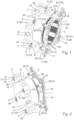
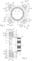
- the wall-mounted connection box unit shown as an example in the figures comprises a box housing body 1 with a rear base section 2 and a sleeve section 3 protruding forward from the base section 2, a functional surface body 7 which has a functional surface 6, and a connecting device 8 which is configured for releasably securing the functional surface body 7 to the base section 2 at different axial heights of the functional surface 6.
- the connecting device 8 comprises at least one connecting structure 9 on the base section 2 radially outside the sleeve section 3 and a connecting body 10 which interacts with the connecting structure 9 and which is arranged to be movable relative to the connecting structure 9 and the functional surface body 7 between a release position 12 and a securing position 13 in a user-operable manner via an actuation interface 11.
- the connecting device 8 includes several connecting structures 9 and correspondingly several connecting bodies 10, wherein in the Figures 3 and 4
- a first connecting body 10 1 is shown in the fixing position 13 and a second connecting body 10 2 is shown in the release position 12.
- the connection structure 9 and the connection body 10 each comprise a plurality of separate individual connection structures or individual connection bodies.
- the connection box unit in the embodiment shown comprises four identical connection bodies 10, ie in addition to the first and second connection bodies 10 1 , 10 2 , a third and a fourth connection body 10 3 , 10 4 , and correspondingly four identical connection structures 9.
- the wall-mounted connection box unit shown can be configured in particular as a sanitary wall-mounted connection box unit for connecting sanitary components to building-side water pipe connections, as explained at the beginning, wherein the sleeve section 3 of the box housing body 1 circumferentially surrounds a built-in component receiving space 4, which is then configured as a sanitary component receiving space and which is accessible via an open front end 5 of the sleeve section 3, via which the built-in component, such as a sanitary component, can be introduced into the box housing body 1.
- the wall-mounted connection box unit is configured as an electrical wall-mounted connection box unit for connecting electrical components to building-side electrical line connections, as also explained at the beginning, wherein the built-in component receiving space 4 then forms an electrical component receiving space into which the relevant electrical component can be introduced into the box housing body 1 via the open front end 5 of the sleeve section 3.
- the open front end 5 of the sleeve section 3 is simultaneously also the open front end 5 of an optional extension sleeve 3a which is held or guided on the sleeve section 3 in an axially height-adjustable manner.
- connection body 14 arranged or held in the base section 2 acts as a fluid or line-connecting link, which has a built-in component connection contour 15 facing the built-in component receiving space 4, i.e. in the sanitary case a sanitary component connection contour and in the electrical case an electrical component connection contour, a line connection interface structure 16 accessible on an outside of the box housing body 1, i.e.
- the functional surface body 7, with its functional surface 6, provides a surface which, in the example shown, fulfills a fastening function by means of which the functional surface body 7 and thus the box housing body 1, to whose base section 2 the functional surface body 7 can be releasably secured, can be fastened to a wall on the building side.
- this fastening function of the functional surface 6 is supported by a plurality of fastening openings 18 with which the functional surface 6 or the functional surface body 7 is provided.
- the functional surface body 7 can be designed such that it fulfills both a fastening function and a sealing function or only a sealing function with its functional surface 6.
- the user can move the respective connecting body 10 between the release position 12 and the fixing position 13 and thereby fix the functional surface body 7 to the base section 2 of the box housing body 1 or release it again for release.
- the actuation interface 11 is set up for the corresponding actuation by the user.
- the actuation interface 11 of the connecting body 10 is located, as in the embodiment shown, on a side 7a of the functional surface body 7 facing away from the base section 2 of the box housing body 1. This allows the user to actuate the movement of the connecting body 10 unhindered by the base section 2 from this side 7a, which is usually still accessible to him even when the connection box unit is already in the mounting position on or in a building wall.
- the connecting body 10 is rotatable between the release position 12 and the fixing position 13.
- the release position 12 is symbolized by the figurative representation of a pivoted-out locking lock 19a and the fixing position 13 by the figurative representation of a pivoted-in locking lock 19b on the functional surface body 7 adjacent to the respective connecting body 10 at marking positions, at which a corresponding rotational position marking 20 of the connecting body 10 is located in the release position 12 or the fixing position 13, as in Fig. 3 explicitly stated.
- the connecting device 8 is configured for selectively detachably fixing the functional surface body 7 in front of a front side 2a or behind a rear side 2b of the base section 2 of the box housing body 1.
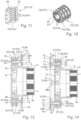
- the fixing of the functional surface body 7 in front of the front side 2a is shown in the view of Fig. 14 fixing the functional surface body 7 behind the back 2b of the base section 2 of the box housing body 1.
- Fig. 4 a front mounting of the functional surface body 7 directly on the front side 2a of the base section 2, ie with a minimum axial zero distance from the base section 2 to the front
- Fig. 4 a front mounting of the functional surface body 7 directly on the front side 2a of the base section 2, ie with a minimum axial zero distance from the base section 2 to the front
- Fig. 4 a front mounting of the functional surface body 7 directly on the front side 2a of the base section 2, ie with a minimum axial zero distance from the base section 2 to the front
- Fig. 4 a front mounting of the functional surface body 7
- Fig. 13 a front mounting of the functional surface body 7 with a larger axial distance from the base section 2 to the front, while Fig. 14 a rear mounting of the functional surface body 7 with approximately the same axial distance from the base section 2 as in the case of Fig. 13 pointing backwards.
- the corresponding design of the connecting device 8 allows several other mounting positions (not shown) for the functional surface body 7 at different axial heights relative to the box housing body 1.
- the connecting device 8 is designed in corresponding designs, depending on requirements, for the stepless or, as in the example shown, multi-stage adjustment of the axial height of the functional surface body 7 relative to the box housing body 1.
- the connecting device 8 is designed, as in the example shown, in such a way that the functional surface body 7 can be mounted on the box housing body 1 both at the front and at the back in several different axial heights of its functional surface 6 on the base section 2; in alternative designs it can only be fixed at a single axial height when mounted on the rear or front.
- the measures that the actuation interface 11 of the connecting body 10 is located on the side 7a of the functional surface body 7 facing away from the base section 2, that the connecting body 10 is rotatable between the release position 12 and the fixing position 13 and that the connecting device 8 is configured for optionally fixing the functional surface body 7 at the front or rear with respect to the base section 2 are all implemented in combination, in alternative designs only one or two of these measures are implemented. This is easily possible since these measures are not necessarily mutually dependent, although a combination of two or all three aspects can lead to specific advantages.
- the actuation interface 11 of the connecting body 10 can be located on a side of the functional surface body 7 facing the base section 2 of the box housing body 1 or laterally radially outward in relation to the base section 2, and/or the connecting device 8 is designed such that the functional surface body 7 can only be fixed to the front or only to the back of the base section 2.
- connection structure 9 is formed by a connection structure element 21 arranged in the base section 2 of the box housing body 1.
- connection structure 9 can, for example, be molded directly onto the base section 2.
- the connecting structure element 21, as in the example shown, includes a sleeve element 22 extending between the front side 2a and the rear side 2b of the base section 2 of the box housing body 1 continuously through the base section 2, as can be seen in particular from the Fig. 1, 2 , 4 and 11 to 14
- the connecting structure element 21 can, for example, be a front side 2a of the base section 2 of the box housing body 1 and/or a connecting piece projecting rearward from the rear side 2b of the base section 2, on which the connecting structure 9 is formed.
- the at least one connecting structure 9, as in the embodiment shown, includes a bolt receiving opening 23 with an opening edge 25 having a locking profile 24, as can be seen in particular from the Fig. 4 and 11 to 14
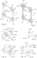
- the connecting body 10 in this case has a connecting bolt 26 which can be inserted into the bolt receiving opening 23 and rotated in the bolt receiving opening 23 between the release position 12 and the fixing position 13, which includes a counter-locking profile 27 on the circumference, as can be seen in particular from the Fig. 1, 2 , 4 , 7 to 10 , 13 and 14 visible.
- the respective connecting structure 9 can be formed as a connecting piece or connecting bolt in the type of the connecting bolt 26 and the respective connecting body 10 can be formed with a piece or bolt receiving opening in the type of the bolt receiving opening 23.
- the actuation interface 11 of the connecting body 10 includes a front-side tool interface 28 of the connecting bolt 26.
- the tool interface 28 is provided on only one or, as in the example shown, on both front sides of the connecting bolt 26.
- the tool interface 28 in the example shown is formed by a polygonal opening extending continuously between the two front sides through the connecting bolt 26, such as a conventional hexagon socket opening, into which a suitable polygonal turning tool, e.g. a screwdriver or an hexagon socket key, can be inserted via each of the two front sides of the connecting bolt 26 in order to rotate the connecting bolt 26 in the bolt receiving opening 23.
- the locking profile 24, as in the example shown, includes one or more axially spaced locking webs 24a, each of which extends within a locking web circumferential sector U R of the bolt receiving opening 23.
- the counter-locking profile 27 includes one or more axially spaced counter-locking webs 27a, each of which extends within a counter-locking web circumferential sector U G .
- the locking profile 24 includes six axially spaced-apart locking webs 24a on two opposite circumferential sector areas U R1 , U R2 , which each extend over a circumferential angle range of approximately 60° to 90° and together form the locking web circumferential sector U R
- the counter-locking profile 27 includes two axially spaced-apart counter-locking webs 27a on two opposite, outer circumferential sector areas U G1 , U G2 , which together form the counter-locking web circumferential sector U G and each extend over a circumferential angle range of approximately 60° to 90°.
- the respective connecting bolt 26 can be inserted axially into the bolt receiving opening 23 of the associated sleeve element 22 in its release position rotational position corresponding to the release position 12, wherein the counter-locking webs 27a are moved axially past the locking webs 24a in the two circumferential angle ranges between the circumferential sector ranges U R1 , U R2 .
- the connecting bolt 26 As soon as the connecting bolt 26 is at the desired axial height, it is rotated from the release position 12 into the fixing position 13 by an associated fixing angle of, for example, approximately 60° to 90°, whereby the counter-locking webs 27a move axially into the spaces between the locking webs 24a and thereby cooperate in a locking or locking manner against axial movements of the connecting bolt 26 in the bolt receiving opening 23.
- an associated fixing angle of, for example, approximately 60° to 90°
- the locking profile 24 contains only one or between two and five or more than six axially spaced locking webs 24a, and/or the counter-locking profile 27 contains only one or more than two axially spaced counter-locking webs 27a. If required, it can be provided to provide a plurality of sleeve elements 22 of different axial lengths and/or a plurality of connecting bolts 26 of different axial lengths in order to then to select a suitable sleeve element 22 or a suitable connecting bolt 26 depending on the desired axial height of the functional surface 6 of the functional surface body 7 to be mounted on the base section 2.
- the locking profile 24 outside the locking web circumferential sector U R and/or the counter-locking profile 27 outside the counter-locking web circumferential sector U G contains at least one locking web 29 within a locking web circumferential sector U A .
- the counter-locking profile 27 formed on the connecting bolt 26 contains one locking web 27b within each of two opposing locking web circumferential sector areas U A1 , U A2 , which together form the locking web circumferential sector U A and each extend in one of the two circumferential angle ranges between the two counter-locking web circumferential sector areas U G1 , U G2 , as can be seen in particular from the Fig. 7, 9 and 10 visible.
- the connecting bolt 26 When the connecting bolt 26 is axially inserted in its release position-rotational position into the bolt receiving opening 23, the locking web circumferential sector U A overlaps with the locking web circumferential sector U R , so that the locking web 27b snaps onto the locking profile 24 in a spring-elastic, radially yielding manner, i.e. snaps along its axial row of locking webs 24a until the connecting bolt 26 has reached a desired axial height and the user stops axially advancing the connecting bolt 26.
- the locking web 27b then holds the connecting bolt 26 pre-fixed in this axial position in cooperation with the two axially adjacent locking webs of the relevant axial row of locking webs 24a, and the user can rotate the connecting bolt 26 from the release position 12 into the fixing position 13 without having to hold it in its axial position by hand.
- the fixing position 13 it is then fixed in the bolt receiving opening 23 in the axial direction by the interaction of the locking webs 24a with the counter-locking webs 27, as explained.
- the connecting bolt 26 can be moved axially out of the bolt receiving opening 23 or further into it by the user for release or for axial height adjustment, wherein the latching web 27b cooperates with the latching webs 24a in a spring-elastic, radially yielding manner in both axial directions of movement and thereby allows this movement in both directions without blocking.
- the connection box unit includes a loss prevention device 29, which holds the connecting body 10 pre-assembled to the functional surface body 7 in a loss-proof manner.
- the loss prevention device 29 comprises two locking spring tongues 29a formed on the circumference on opposite sides of the connecting bolt 26, each with a radially outwardly projecting locking cam 29b, as can be seen in particular from the Fig. 7, 9 and 10
- the locking cams are designed to engage behind an opening edge of a connecting body through-opening 30, which is formed on the functional surface body 7, in order to be able to insert the connecting body 10 through it, as can be seen in particular from the Fig. 5 and 6 visible.
- the connecting body 10 or the connecting bolt 26 with a widened head part 31 comes to rest on the front against the edge of the connecting body through-opening 30 and engages this opening edge with the locking cams 29b which are resiliently flexible in the radial direction.
- the connecting body 10 or the connecting bolt 26 is held loosely and rotationally movable and captively pre-assembled on the functional surface body 7.
- connection box unit includes an end position latch 32, which latches the connecting body 10 or connecting bolt 26 in the fixing position 13 so that it can be disengaged on the functional surface body 7.
- the end position latch 32 comprises two latching lugs 32a formed on the circumference of the head part 31 of the connecting bolt 26 and corresponding latching recesses 32b on the opening edge of the respective connecting body through-opening 30 of the functional surface body 7, as can be seen in particular from the Fig. 5 and 8
- the end position locking mechanism 32 prevents the connecting bolt 26 from accidentally coming out or turning back from the fixing position 13 in the direction of the release position 12.
- the end position locking mechanism 32 is configured in such a way that the connecting body 10 or connecting bolt 26 can be unlocked by the user using a small turning force if the user wants to move the connecting body 7 or connecting bolt 26 from its fixing position 13 to its release position 12.
- the connection box unit includes an anti-twist device 33, which has corresponding end position stops 33a, 33b on the connecting body 10 or connecting bolt 26 on the one hand and on the functional surface body 7 or on the connecting structure 9 on the other hand.
- the anti-twist device 33 includes, on the one hand, stop lugs 33a on the connecting bolt 26, wherein the stop lugs 33a can preferably be formed by the locking cams 29b, and, on the other hand, opening edge shoulders 33b on the opening edge of the respective connecting body through-opening 30 of the functional surface body 7, against which the respective stop lug 33a comes to rest when the connecting bolt 26 is rotated into its release position 12 or into its fixing position 13.
- the functional surface body 7 includes a closed ring body 34 with a sleeve section through-opening 35 and the already mentioned, at least one connecting body through-opening 30, as can be seen in particular from the Fig. 1 to 3 , 5 and 6 visible.
- the ring body 34 is pushed onto the box housing body 1 from the front, whereby its sleeve section 3 can pass through the sleeve section through-opening 35, so that the ring body 34 surrounds the sleeve section 3 in a closed manner.
- the ring body 34 has four connecting body through-openings 30 at a circumferential angular distance of approximately 90° each, whereby the ring body 34 is provided in the relevant areas with radially outwardly extending extensions 34a, 34b, 34c, 34d, in which the fastening openings 18 already mentioned above are also formed.
- the sleeve section 3 and the base section 2 of the box housing body 1 are formed in one piece from a plastic foam material, wherein the connecting structure 9 is molded onto the base section 2 or the connecting structure element 21 is embedded in the plastic foam material of the base section 2.
- the sleeve element 22 can be embedded in the plastic foam material of the base section 2 or foamed around the circumference by it in a single manufacturing process during the manufacture of the box housing body.
- the box housing body 1 does not consist of a plastic foam material, but for example of a more rigid plastic material.
- the sleeve element 22 or the connecting structure element 21 can, in this and other cases, be made of a hard, rigid plastic material or a metal material, for example. If the base section 2 of the box housing body 1 is made of a rigid plastic or metal material, the connecting structure 9 can also be realized directly as a structure integrated into the base section 2. Likewise, the connecting body 10 and the functional surface body 7 can be made of any plastic or metal material, depending on the requirements and application. The same applies to the connecting body 14.
- the invention provides a wall-mounted connection box unit which offers particular functional advantages and/or advantages in terms of manufacturing and/or assembly effort, especially with regard to the flexible usability of the connection box unit due to the variable fixability of the functional surface body on the box housing body and/or the realization of the connecting device for releasably fixing the functional surface body on the base section of the box housing body.
- connection box unit can be used particularly advantageously as a sanitary wall-mounted connection box unit in sanitary installation technology and as an electrical wall-mounted connection box unit in electrical installation technology in connection with the installation of sanitary or electrical components, whether in a flush-mounted or surface-mounted version, on a side, ceiling or floor wall of a sanitary room or a kitchen or another room in a building.
Landscapes
- Engineering & Computer Science (AREA)
- Health & Medical Sciences (AREA)
- Life Sciences & Earth Sciences (AREA)
- Hydrology & Water Resources (AREA)
- Public Health (AREA)
- Water Supply & Treatment (AREA)
- Civil Engineering (AREA)
- Architecture (AREA)
- Structural Engineering (AREA)
- General Engineering & Computer Science (AREA)
- Mechanical Engineering (AREA)
- Connection Or Junction Boxes (AREA)
- Casings For Electric Apparatus (AREA)
- Quick-Acting Or Multi-Walled Pipe Joints (AREA)
Claims (14)
- Unité de boîtier de raccordement à encastrer dans un mur, comprenant- un corps de boîtier (1) présentant une portion de base arrière (2) et une portion de douille (3) faisant saillie vers l'avant depuis la portion de base, qui entoure, à la périphérie, un espace de réception (4) de composants encastrés accessible par une extrémité frontale avant ouverte (5) de la portion de douille,- un corps à surface fonctionnelle (7) présentant une surface fonctionnelle (6), et- un dispositif de liaison (8) qui est configuré pour immobiliser de manière amovible le corps à surface fonctionnelle sur la portion de base à différentes hauteurs axiales de la surface fonctionnelle et qui comprend au moins une structure de liaison (9) sur la portion de base radialement à l'extérieur de la portion de douille et un corps de liaison (10) coopérant avec la structure de liaison, qui est disposé de manière mobile par rapport à la structure de liaison et au corps à surface fonctionnelle entre une position de libération (12) et une position d'immobilisation (13) par l'intermédiaire d'une interface d'actionnement (11) pouvant être actionnée par l'utilisateur,
caractérisée en ce que- le corps de liaison (10) est mobile en rotation entre la position de libération (12) et la position d'immobilisation (13). - Unité de boîtier de raccordement à encastrer dans un mur selon la revendication 1,
caractérisée en outre en ce que- l'interface d'actionnement (11) du corps de liaison (10) se trouve sur une face (7a) du corps à surface fonctionnelle (7) détournée de la portion de base (2) du corps de boîtier (1), et/ou- le dispositif de liaison (8) est configuré pour immobiliser sélectivement et de manière amovible le corps à surface fonctionnelle (7) en avant d'une face avant (2a) ou en arrière d'une face arrière (2b) de la portion de base (2) du corps de boîtier (1). - Unité de boîtier de raccordement à encastrer dans un mur selon la revendication 1 ou 2,
caractérisée en outre en ce que ladite au moins une structure de liaison est formée par un élément de structure de liaison (21) disposé dans la portion de base du corps de boîtier. - Unité de boîtier de raccordement à encastrer dans un mur selon la revendication 3,
caractérisée en outre en ce que l'élément de structure de liaison comprend un élément de douille (22) s'étendant en continu à travers la portion de base entre une face avant (2a) et une face arrière (2b) de la portion de base. - Unité de boîtier de raccordement à encastrer dans un mur selon l'une des revendications 1 à 4,
caractérisée en outre en ce que ladite au moins une structure de liaison présente une ouverture de réception de boulon (23) ayant un bord d'ouverture (25) présentant un profil d'enclenchement (24), et le corps de liaison comprend un boulon de liaison (26) pouvant être inséré dans l'ouverture de réception de boulon et pouvant tourner dans l'ouverture de réception de boulon entre la position de libération et la position d'immobilisation, qui présente sur sa périphérie un profil d'enclenchement complémentaire (27), le profil d'enclenchement et le profil d'enclenchement complémentaire coopérant par verrouillage, dans la position d'immobilisation du boulon de liaison, pour empêcher le boulon de liaison de sortir axialement hors de l'ouverture de réception de boulon, et autorisant, dans la position de libération du boulon de liaison, un mouvement de sortie axial du boulon de liaison hors de l'ouverture de réception de boulon. - Unité de boîtier de raccordement à encastrer dans un mur selon la revendication 5,
caractérisée en outre en ce que l'interface d'actionnement du corps de liaison comprend une interface d'outil frontale (28) du boulon de liaison. - Unité de boîtier de raccordement à encastrer dans un mur selon la revendication 5 ou 6,
caractérisée en outre en ce que le profil d'enclenchement comprend une ou plusieurs nervures d'enclenchement (24a) espacées axialement les unes des autres, qui s'étendent chacune à l'intérieur d'un secteur périphérique de nervure d'enclenchement (UR) de l'ouverture de réception de boulon, et le profil d'enclenchement complémentaire comprend une ou plusieurs nervures d'enclenchement complémentaires (27a) espacées axialement les unes des autres, qui s'étendent chacune à l'intérieur d'un secteur périphérique de nervure d'enclenchement complémentaire (UG). - Unité de boîtier de raccordement à encastrer dans un mur selon l'une des revendications 5 à 7,
caractérisée en outre en ce que le profil d'enclenchement, à l'extérieur du secteur périphérique de nervure d'enclenchement, et/ou le profil d'enclenchement complémentaire, à l'extérieur du secteur périphérique de nervure d'enclenchement complémentaire, comprend au moins une nervure à crans (27b) à l'intérieur d'un secteur périphérique de nervure à crans (UA). - Unité de boîtier de raccordement à encastrer dans un mur selon l'une des revendications 1 à 8,
caractérisée en outre par un dispositif anti-perte (29) qui maintient le corps de liaison prémonté sur le corps à surface fonctionnelle de manière à éviter toute perte. - Unité de boîtier de raccordement à encastrer dans un mur selon l'une des revendications 1 à 9,
caractérisée en outre par un cran de fin de course (32) qui, en position d'immobilisation, fait enclencher le corps de liaison sur le corps à surface fonctionnelle de manière à pouvoir le désenclencher. - Unité de boîtier de raccordement à encastrer dans un mur selon l'une des revendications 1 à 10,
caractérisée en outre par un dispositif anti-rotation (33) qui comprend des butées de fin de course correspondantes (33a, 33b) sur le corps de liaison, d'une part, et sur le corps à surface fonctionnelle ou sur la structure de liaison, d'autre part. - Unité de boîtier de raccordement à encastrer dans un mur selon l'une des revendications 1 à 11,
caractérisée en outre en ce que le corps à surface fonctionnel comprend un corps annulaire fermé (34) ayant une ouverture (35) de passage de portion de douille et au moins une ouverture (30) de passage de corps de liaison. - Unité de boîtier de raccordement à encastrer dans un mur selon l'une des revendications 1 à 12,
caractérisée en outre en ce que la portion de douille et la portion de base du corps de boîtier sont formées d'un seul tenant à partir d'un matériau en mousse plastique, la structure de liaison étant moulée sur la portion de base. - Unité de boîtier de raccordement à encastrer dans un mur selon l'une des revendications 3 à 13,
caractérisée en outre en ce que la portion de douille et la portion de base du corps de boîtier sont formées d'un seul tenant à partir d'un matériau en mousse plastique, l'élément de structure de liaison étant noyé dans le matériau en mousse plastique de la portion de base.
Applications Claiming Priority (2)
| Application Number | Priority Date | Filing Date | Title |
|---|---|---|---|
| DE102020203794.9A DE102020203794A1 (de) | 2020-03-24 | 2020-03-24 | Wandeinbau-Anschlussboxeinheit mit Funktionsflächenkörper |
| EP21164311.9A EP3885499B1 (fr) | 2020-03-24 | 2021-03-23 | Unité de boîtier de raccordement destinée à être encastrée pourvu de corps de surface fonctionnel |
Related Parent Applications (2)
| Application Number | Title | Priority Date | Filing Date |
|---|---|---|---|
| EP21164311.9A Division-Into EP3885499B1 (fr) | 2020-03-24 | 2021-03-23 | Unité de boîtier de raccordement destinée à être encastrée pourvu de corps de surface fonctionnel |
| EP21164311.9A Division EP3885499B1 (fr) | 2020-03-24 | 2021-03-23 | Unité de boîtier de raccordement destinée à être encastrée pourvu de corps de surface fonctionnel |
Publications (4)
| Publication Number | Publication Date |
|---|---|
| EP4254694A2 EP4254694A2 (fr) | 2023-10-04 |
| EP4254694A3 EP4254694A3 (fr) | 2023-11-29 |
| EP4254694C0 EP4254694C0 (fr) | 2024-11-13 |
| EP4254694B1 true EP4254694B1 (fr) | 2024-11-13 |
Family
ID=75203012
Family Applications (3)
| Application Number | Title | Priority Date | Filing Date |
|---|---|---|---|
| EP23187162.5A Active EP4254694B1 (fr) | 2020-03-24 | 2021-03-23 | Unité de boîtier de raccordement destinée à être encastrée pourvu de corps de surface fonctionnel |
| EP23187164.1A Active EP4254695B1 (fr) | 2020-03-24 | 2021-03-23 | Unité de boîtier de raccordement destinée à être encastrée pourvu de corps de surface fonctionnel |
| EP21164311.9A Active EP3885499B1 (fr) | 2020-03-24 | 2021-03-23 | Unité de boîtier de raccordement destinée à être encastrée pourvu de corps de surface fonctionnel |
Family Applications After (2)
| Application Number | Title | Priority Date | Filing Date |
|---|---|---|---|
| EP23187164.1A Active EP4254695B1 (fr) | 2020-03-24 | 2021-03-23 | Unité de boîtier de raccordement destinée à être encastrée pourvu de corps de surface fonctionnel |
| EP21164311.9A Active EP3885499B1 (fr) | 2020-03-24 | 2021-03-23 | Unité de boîtier de raccordement destinée à être encastrée pourvu de corps de surface fonctionnel |
Country Status (10)
| Country | Link |
|---|---|
| US (1) | US11982072B2 (fr) |
| EP (3) | EP4254694B1 (fr) |
| CN (1) | CN113445580B (fr) |
| DE (1) | DE102020203794A1 (fr) |
| ES (3) | ES3054870T3 (fr) |
| PL (3) | PL3885499T3 (fr) |
| RU (1) | RU2769331C1 (fr) |
| SA (1) | SA121420595B1 (fr) |
| SG (1) | SG10202102867SA (fr) |
| ZA (1) | ZA202101864B (fr) |
Families Citing this family (8)
| Publication number | Priority date | Publication date | Assignee | Title |
|---|---|---|---|---|
| DE102020203797A1 (de) | 2020-03-24 | 2021-09-30 | Hansgrohe Se | Wandeinbau-Anschlussboxeinheit mit Verlängerungshülse |
| DE102020203792A1 (de) | 2020-03-24 | 2021-09-30 | Hansgrohe Se | Wandeinbau-Anschlussboxeinheit |
| DE102020203800A1 (de) * | 2020-03-24 | 2021-09-30 | Hansgrohe Se | Sanitäre Wandeinbau-Anschlussboxeinheit mit elektrischer Leitungsdurchführung |
| DE102020203794A1 (de) * | 2020-03-24 | 2021-09-30 | Hansgrohe Se | Wandeinbau-Anschlussboxeinheit mit Funktionsflächenkörper |
| DE102022119002A1 (de) | 2022-07-28 | 2024-02-08 | Franz Joseph Schütte GmbH | Unterputzbox für einen Anschlusskörper zum Anschluss einer Armatur |
| DE202023002746U1 (de) | 2023-02-21 | 2024-05-02 | Hansgrohe Se | Schraubverbindung und Funktionsblock für Installationsanschluss |
| DE102023201513A1 (de) | 2023-02-21 | 2024-08-22 | Hansgrohe Se | Fluidsteuerventilvorrichtung und Funktionsblock für Installationsanschlussbox |
| DE102023129046A1 (de) * | 2023-10-23 | 2025-04-24 | Grohe Ag | Unterputzeinbaukörper für eine Sanitärarmatur |
Citations (1)
| Publication number | Priority date | Publication date | Assignee | Title |
|---|---|---|---|---|
| DE20321431U1 (de) * | 2002-07-18 | 2007-04-05 | Hansgrohe Ag | Installationseinrichtung für Sanitärelement |
Family Cites Families (85)
| Publication number | Priority date | Publication date | Assignee | Title |
|---|---|---|---|---|
| US1822056A (en) | 1929-02-07 | 1931-09-08 | Gillette Vibber Company Inc | Threadless pipe connecter |
| US2297862A (en) | 1939-08-30 | 1942-10-06 | Walter H Bachmann | Switch box |
| GB622374A (en) | 1946-03-16 | 1949-05-02 | Du Pont | Improvements in and relating to the photo-polymerisation of compounds containing theethylene double bond |
| DE2637719C3 (de) | 1976-08-21 | 1979-02-22 | Hansa Metallwerke Ag, 7000 Stuttgart | Unterputz-Armatur |
| US4265365A (en) | 1978-04-28 | 1981-05-05 | Slater Electric Inc. | Moisture resistant electrical outlet box |
| US4181329A (en) | 1979-02-02 | 1980-01-01 | Gordon H. Cork | Releasable tube coupling |
| US4265265A (en) | 1979-09-10 | 1981-05-05 | Chicago Pneumatic Tool Company | Pneumatic tool governor |
| DE3310138C2 (de) | 1983-03-21 | 1986-07-24 | Thyssen Plastik Anger KG, 8000 München | Installationsdoseneinheit |
| DE3907588A1 (de) | 1989-03-09 | 1990-09-13 | Grohe Armaturen Friedrich | Befestigungsvorrichtung |
| ATA242889A (de) | 1989-10-23 | 1995-06-15 | Geberit Ag | Geschäumter installationsbaustein für sanitäreinrichtungen |
| CH681237A5 (fr) | 1990-07-26 | 1993-02-15 | Nussbaum & Co Ag R | |
| DE9115323U1 (de) | 1991-12-11 | 1993-04-08 | Grote & Hartmann Gmbh & Co Kg, 5600 Wuppertal | Dichtungsstopfen für elektrische Leitungen |
| DE4241989A1 (de) | 1992-12-12 | 1994-06-16 | Grohe Armaturen Friedrich | Unterputz-Armatur |
| DE4417485C2 (de) | 1994-05-19 | 1997-08-28 | Hansa Metallwerke Ag | Sanitärarmatur |
| US5783774A (en) | 1996-10-21 | 1998-07-21 | Walker Systems, Inc. | Non-metallic floor box |
| DE19648587B4 (de) | 1996-11-23 | 2004-04-15 | Hansa Metallwerke Ag | Unterputz-Einbaukasten für Sanitärarmaturen |
| DE19715651B4 (de) | 1997-04-15 | 2005-09-29 | Ortwein Sanitär Original Heizung GmbH | Vorrichtung zum schall- und wärmedämmenden Anschluß von Sanitärarmaturen etc. |
| US5913439A (en) | 1997-08-29 | 1999-06-22 | Watlow Electric Manufacturing Co. | Mounting assembly with dual mount collar |
| GB2337287A (en) | 1998-05-13 | 1999-11-17 | Barber Eduard & Co Ltd | Boundary box |
| DE19856156A1 (de) | 1998-12-05 | 2000-06-08 | Grohe Kg Hans | Befestigungsanordnung für sanitäre Bauteile |
| DE10036996A1 (de) | 2000-07-06 | 2002-01-17 | Illbruck Gmbh | Wannenträger-Anbauelement |
| US6499771B1 (en) | 2000-07-18 | 2002-12-31 | Victaulic Company Of America | Mechanical pipe coupling with toothed retainer |
| DE20105345U1 (de) | 2001-03-26 | 2001-07-12 | Eisenwerk Wittigsthal GmbH, 08349 Johanngeorgenstadt | Montageeinheit für die Sanitär- und Heizungsinstallation |
| DE10122022A1 (de) | 2001-05-07 | 2002-11-14 | Grohe Armaturen Friedrich | Unterputzwasserarmatur |
| JP4398115B2 (ja) | 2001-06-13 | 2010-01-13 | 未来工業株式会社 | 管引出具 |
| AU2003214029A1 (en) | 2002-03-27 | 2003-10-08 | Daxtor Aps | Expansion unit |
| EP1355399B8 (fr) | 2002-04-19 | 2010-03-03 | C & C MARSHALL LIMITED | Accessoire de montage |
| DE10233858A1 (de) | 2002-07-18 | 2004-01-29 | Hansgrohe Ag | Installationseinrichtung für Sanitärelemente |
| US20050194785A1 (en) | 2003-10-03 | 2005-09-08 | Sami Shemtov | Rain tight compression fitting coupling device |
| US7458389B2 (en) * | 2004-04-19 | 2008-12-02 | Mark Doverspike | Bracket system for securing a single-lever-valves and associated water pipework to a support board |
| DE102004060744A1 (de) | 2004-12-15 | 2006-06-22 | Kludi Gmbh & Co. Kg | Unterputz-Gehäuse für eine Wasseranschlusseinheit |
| US6992252B1 (en) | 2005-03-29 | 2006-01-31 | Sigma Electric Manufacturing Corp. | Reducer bushing for weatherproof outlet boxes |
| FI118447B (fi) | 2005-11-17 | 2007-11-15 | Ensto Busch Jaeger Oy | Koje- tai jakorasia |
| GB2443693B (en) * | 2006-11-10 | 2009-09-09 | Ambar Kelly Ltd | Service box |
| DE102007002235A1 (de) | 2007-01-10 | 2008-07-17 | Markus Morent | Vorrichtung zur Installation einer Sanitär- und/oder Elektrokomponente an einem Tragelement |
| US8480134B2 (en) | 2007-05-25 | 2013-07-09 | Quick Fitting, Inc. | Piping joint assembly system and method with sealing ring stabilizer |
| US7462775B1 (en) * | 2007-06-25 | 2008-12-09 | Arlington Industries, Inc. | Adjustable electrical box for flush or offset mounting of electrical devices on brick or stone walls |
| DE102007044284A1 (de) | 2007-09-07 | 2009-03-12 | Hansgrohe Ag | Anschlussanordnung |
| US8474877B2 (en) | 2007-09-19 | 2013-07-02 | Bridgeport Fittings, Inc. | Push-in fitting for electrical metallic tubing with enhanced sealing and continuity |
| DE102008013736B4 (de) | 2008-03-11 | 2017-07-06 | Ideal Standard International Nv | Einbaukasten zum variablen Einbau von Sanitärarmaturen |
| DE102008027382A1 (de) | 2008-06-09 | 2009-12-17 | Uponor Innovation Ab | Pressfitting für ein Rohr, insbesondere Kunststoffrohr oder Kunststoff-Metall-Verbundrohr |
| AT507052B1 (de) | 2008-06-17 | 2010-07-15 | Baumgartner Johannes | Wandeinbaublock für installationen |
| US8899431B1 (en) | 2008-09-12 | 2014-12-02 | Hubbell Incorporated | Extendable electrical box |
| US8158884B2 (en) | 2008-11-17 | 2012-04-17 | Thomas & Betts International, Inc. | Angled slots for installation of outdoor metallic boxes |
| DE102008064253B3 (de) | 2008-12-20 | 2010-02-11 | Ideal Standard International Bvba | Unterputzkasten für die Montage von Sanitärbauteilen |
| AT507426B1 (de) | 2008-12-23 | 2010-05-15 | Alois Mochart | Montageblock für den anschluss von geräten |
| DE102009012838B3 (de) | 2009-03-04 | 2010-08-19 | Hansgrohe Ag | Gehäuse für eine Armatur |
| DE102009012840B3 (de) | 2009-03-04 | 2010-08-19 | Hansgrohe Ag | Anschlussblock für Sanitärarmaturen |
| DE102009049711A1 (de) | 2009-10-17 | 2011-04-21 | Abb Ag | Elektro-Installationsgerät mit Trägerrahmen und Wandausgleichselementen |
| DE212010000212U1 (de) | 2010-03-29 | 2013-04-22 | Robert Bosch Limitada | Dichte elektrische Verbinderanordnung |
| DE102010055805A1 (de) * | 2010-12-23 | 2012-06-28 | Ideal-Standard International Bvba | Unterputz-Einbaukasten für ein eine elektronisch ansteuerbare Temperatur- und Volumensteuereinheit aufwesendes Mischmodul |
| US8398122B2 (en) | 2010-12-30 | 2013-03-19 | Quick Fitting, Inc. | Push connect joint assembly, system and method |
| US9725892B2 (en) | 2011-04-28 | 2017-08-08 | Sioux Chief Mfg. Co., Inc. | Plumbing supply line mounting and finish panel assembly |
| US9086179B1 (en) | 2011-06-16 | 2015-07-21 | Naris Komolrochanaporn | Quick coupling pipe fitting system |
| DE102012203393A1 (de) | 2012-03-05 | 2013-09-05 | Hansgrohe Se | Höheneinstellbarer Putzdickenausgleich eines iBox Grundsets |
| DE102012011599C5 (de) | 2012-06-13 | 2023-11-16 | Rose Plastic Ag | Polygonartige Schiebeverpackung mit Dreh-Schub-Bewegung zum Öffnen und Verschließen |
| DK2822121T3 (en) | 2013-07-05 | 2018-06-14 | Schneider Electric Danmark As | Extension assembly for an electrical wiring box |
| WO2015096811A1 (fr) | 2013-12-27 | 2015-07-02 | 厦门松霖科技有限公司 | Ensemble préintégré encastré |
| DE202014106179U1 (de) | 2014-01-09 | 2015-03-23 | Wolfgang Hofmann | Höhenverstellbare Straßenkappe |
| DE102014208291B4 (de) | 2014-05-02 | 2018-02-15 | Icotek Project Gmbh & Co. Kg | Vorrichtung zum Hindurchführen und Einspannen von Kabeln |
| DE102014107655B4 (de) | 2014-05-30 | 2024-07-11 | Voss Automotive Gmbh | Steckverbinder für Fluidleitungen mit innenliegender Adapterhülse |
| DE202015001883U1 (de) | 2015-03-09 | 2016-06-10 | Neoperl Gmbh | Sanitäres Einsetzelement |
| PL3271518T3 (pl) | 2015-03-16 | 2020-11-16 | Fir Italia S.P.A. | Uniwersalny osadzony system do części składowych baterii sanitarnej |
| US9667053B2 (en) * | 2015-06-01 | 2017-05-30 | Hubbell Incorporated | Adjustable floor box |
| CN204732809U (zh) | 2015-06-09 | 2015-10-28 | 张少伟 | 一种电器接线盒 |
| DE102015112420A1 (de) | 2015-07-29 | 2017-02-02 | Kaiser Gmbh & Co. Kg | Installationsdose |
| AT517356B1 (de) | 2015-12-04 | 2017-01-15 | Wogro Gmbh | Installationsdose für wenigstens einen Leitungsanschluss |
| ES2952103T3 (es) | 2016-04-21 | 2023-10-27 | Jarola Vision B V | Sistema de construcción modular, elemento de acoplamiento, objeto, herramienta y embalaje |
| US10280598B2 (en) | 2016-05-16 | 2019-05-07 | Dahata Inc. | Faucet assembly |
| US10006577B2 (en) | 2016-07-15 | 2018-06-26 | Miniature Precision Components, Inc. | Permanent quick connector and assembly therewith |
| US10186852B2 (en) | 2016-10-28 | 2019-01-22 | Allied Moulded Products, Inc. | Seal for electrical box |
| DE102017100707A1 (de) | 2017-01-16 | 2018-07-19 | Grohe Ag | Unterputzbox für einen Armaturenkörper mit einem Befestigungsrahmen |
| DE102017100710A1 (de) | 2017-01-16 | 2018-07-19 | Grohe Ag | Unterputzeinbaukörper für eine Sanitärarmatur mit einem zweiteiligen Gehäuse |
| ES2930049T3 (es) | 2017-03-23 | 2022-12-05 | Fischer Georg Jrg Ag | Conector de conexión |
| US10865922B2 (en) | 2017-10-05 | 2020-12-15 | Novares Us Engine Components, Inc. | Anti-tamper permanent quick connect coupling device |
| DE102017127151A1 (de) | 2017-11-17 | 2019-05-23 | Grohe Ag | Unterputzeinbaukörper für eine Sanitärarmatur mit einer Kabeldurchführung |
| US11209083B2 (en) | 2018-01-18 | 2021-12-28 | Specified Technologies Inc. | Self-sealing membrane sleeve assembly |
| FI3570396T3 (fi) | 2018-05-14 | 2023-04-25 | Schneider Electric Ind Sas | Säädettävä rengaskokoonpano sähköasennusrasiaa varten |
| CN208461082U (zh) | 2018-07-23 | 2019-02-01 | 佳能企业股份有限公司 | 电子系统、出线口结构及缆线 |
| CN209388954U (zh) | 2019-03-11 | 2019-09-13 | 南京铁道职业技术学院 | 一种继电器保护罩 |
| DE102020203792A1 (de) * | 2020-03-24 | 2021-09-30 | Hansgrohe Se | Wandeinbau-Anschlussboxeinheit |
| DE102020203800A1 (de) * | 2020-03-24 | 2021-09-30 | Hansgrohe Se | Sanitäre Wandeinbau-Anschlussboxeinheit mit elektrischer Leitungsdurchführung |
| DE102020203794A1 (de) * | 2020-03-24 | 2021-09-30 | Hansgrohe Se | Wandeinbau-Anschlussboxeinheit mit Funktionsflächenkörper |
| DE102020203797A1 (de) | 2020-03-24 | 2021-09-30 | Hansgrohe Se | Wandeinbau-Anschlussboxeinheit mit Verlängerungshülse |
| EP4002617A1 (fr) | 2020-11-13 | 2022-05-25 | Eaton Intelligent Power Limited | Ensemble bague à profondeur réglable et procédé d'installation |
-
2020
- 2020-03-24 DE DE102020203794.9A patent/DE102020203794A1/de not_active Withdrawn
-
2021
- 2021-03-18 RU RU2021107167A patent/RU2769331C1/ru active
- 2021-03-19 ZA ZA2021/01864A patent/ZA202101864B/en unknown
- 2021-03-22 SG SG10202102867S patent/SG10202102867SA/en unknown
- 2021-03-23 ES ES23187164T patent/ES3054870T3/es active Active
- 2021-03-23 PL PL21164311.9T patent/PL3885499T3/pl unknown
- 2021-03-23 EP EP23187162.5A patent/EP4254694B1/fr active Active
- 2021-03-23 ES ES23187162T patent/ES3012396T3/es active Active
- 2021-03-23 US US17/209,877 patent/US11982072B2/en active Active
- 2021-03-23 PL PL23187164.1T patent/PL4254695T3/pl unknown
- 2021-03-23 EP EP23187164.1A patent/EP4254695B1/fr active Active
- 2021-03-23 PL PL23187162.5T patent/PL4254694T3/pl unknown
- 2021-03-23 EP EP21164311.9A patent/EP3885499B1/fr active Active
- 2021-03-23 ES ES21164311T patent/ES2962224T3/es active Active
- 2021-03-24 CN CN202110312348.4A patent/CN113445580B/zh active Active
- 2021-03-24 SA SA121420595A patent/SA121420595B1/ar unknown
Patent Citations (1)
| Publication number | Priority date | Publication date | Assignee | Title |
|---|---|---|---|---|
| DE20321431U1 (de) * | 2002-07-18 | 2007-04-05 | Hansgrohe Ag | Installationseinrichtung für Sanitärelement |
Also Published As
| Publication number | Publication date |
|---|---|
| EP3885499A1 (fr) | 2021-09-29 |
| SG10202102867SA (en) | 2021-10-28 |
| EP4254694C0 (fr) | 2024-11-13 |
| US20210301507A1 (en) | 2021-09-30 |
| PL4254695T3 (pl) | 2026-01-26 |
| CN113445580A (zh) | 2021-09-28 |
| ZA202101864B (en) | 2022-07-27 |
| US11982072B2 (en) | 2024-05-14 |
| CN113445580B (zh) | 2023-08-08 |
| DE102020203794A1 (de) | 2021-09-30 |
| EP3885499B1 (fr) | 2023-08-30 |
| ES3012396T3 (en) | 2025-04-09 |
| EP4254695A2 (fr) | 2023-10-04 |
| EP4254694A3 (fr) | 2023-11-29 |
| EP4254694A2 (fr) | 2023-10-04 |
| EP4254695C0 (fr) | 2025-08-27 |
| PL4254694T3 (pl) | 2025-04-07 |
| SA121420595B1 (ar) | 2023-01-26 |
| ES2962224T3 (es) | 2024-03-18 |
| EP4254695B1 (fr) | 2025-08-27 |
| EP4254695A3 (fr) | 2023-11-22 |
| RU2769331C1 (ru) | 2022-03-30 |
| PL3885499T3 (pl) | 2024-03-11 |
| ES3054870T3 (en) | 2026-02-06 |
Similar Documents
| Publication | Publication Date | Title |
|---|---|---|
| EP4254694B1 (fr) | Unité de boîtier de raccordement destinée à être encastrée pourvu de corps de surface fonctionnel | |
| EP2101002B1 (fr) | Boîtier d'encastrement destiné à l'encastrement variable d'armatures sanitaires | |
| EP1845208B1 (fr) | Dispositif d'installation pour éléments sanitaires | |
| DE102005042212B4 (de) | Sanitäres Einbauteil | |
| EP3268545B1 (fr) | Robinet avec rosace | |
| EP2876222B1 (fr) | Unité comportant un dispositif de fixation pour un WC suspendu et un élément du support | |
| EP3885497B1 (fr) | Unité de boîtier de raccordement destinée à être encastrée pourvu de manchon d'extension | |
| DE102015219175B4 (de) | Anschlussrohrstutzen für eine Sanitärarmatur | |
| EP1006244A2 (fr) | Dispositif de fixation pour éléments sanitaires | |
| DE102007023639A1 (de) | Anschlussvorrichtung für Leuchten | |
| DE19853974C1 (de) | Abdeck-Rosette für den Anschlußbereich einer sanitären Wandarmatur | |
| DE102013003823B4 (de) | Sanitärarmatur mit einer Rosette | |
| DE102014216975B4 (de) | Sanitärbrause | |
| DE19853950B4 (de) | Abdeck-Rosette | |
| DE4422888C2 (de) | Isolierummantelung für Rohraustrittsbögen von Wasserleitungen | |
| WO2014135241A1 (fr) | Brise-jet pourvu d'un boîtier encastré | |
| DE102004034150B4 (de) | Sanitäre Unterputzarmatur | |
| DE102013016103B4 (de) | Anschlusskörper für eine sanitare Unterputzarmatur | |
| DE202023002746U1 (de) | Schraubverbindung und Funktionsblock für Installationsanschluss | |
| EP0898919B1 (fr) | Elément de réglage pour dispositif de douche ou équivalent | |
| EP4303371B1 (fr) | Robinetterie sanitaire pourvue d'élément de verrouillage | |
| EP1723285B1 (fr) | Systeme de douche | |
| EP4424934A1 (fr) | Rosette de recouvrement et ensemble de montage pour connexion d'installation | |
| DE202012100198U1 (de) | Befestigungsanordnung für sanitäre Bauteile | |
| EP0961070A2 (fr) | Raccord rapide |
Legal Events
| Date | Code | Title | Description |
|---|---|---|---|
| PUAI | Public reference made under article 153(3) epc to a published international application that has entered the european phase |
Free format text: ORIGINAL CODE: 0009012 |
|
| STAA | Information on the status of an ep patent application or granted ep patent |
Free format text: STATUS: THE APPLICATION HAS BEEN PUBLISHED |
|
| AC | Divisional application: reference to earlier application |
Ref document number: 3885499 Country of ref document: EP Kind code of ref document: P |
|
| AK | Designated contracting states |
Kind code of ref document: A2 Designated state(s): AL AT BE BG CH CY CZ DE DK EE ES FI FR GB GR HR HU IE IS IT LI LT LU LV MC MK MT NL NO PL PT RO RS SE SI SK SM TR |
|
| REG | Reference to a national code |
Ref country code: DE Ref legal event code: R079 Free format text: PREVIOUS MAIN CLASS: H02G0003180000 Ref country code: DE Ref legal event code: R079 Ref document number: 502021005830 Country of ref document: DE Free format text: PREVIOUS MAIN CLASS: H02G0003180000 Ipc: E03C0001020000 |
|
| PUAL | Search report despatched |
Free format text: ORIGINAL CODE: 0009013 |
|
| AK | Designated contracting states |
Kind code of ref document: A3 Designated state(s): AL AT BE BG CH CY CZ DE DK EE ES FI FR GB GR HR HU IE IS IT LI LT LU LV MC MK MT NL NO PL PT RO RS SE SI SK SM TR |
|
| RIC1 | Information provided on ipc code assigned before grant |
Ipc: H02G 3/18 20060101ALI20231024BHEP Ipc: H02G 3/12 20060101ALI20231024BHEP Ipc: E03C 1/02 20060101AFI20231024BHEP |
|
| STAA | Information on the status of an ep patent application or granted ep patent |
Free format text: STATUS: REQUEST FOR EXAMINATION WAS MADE |
|
| 17P | Request for examination filed |
Effective date: 20240422 |
|
| RBV | Designated contracting states (corrected) |
Designated state(s): AL AT BE BG CH CY CZ DE DK EE ES FI FR GB GR HR HU IE IS IT LI LT LU LV MC MK MT NL NO PL PT RO RS SE SI SK SM TR |
|
| GRAP | Despatch of communication of intention to grant a patent |
Free format text: ORIGINAL CODE: EPIDOSNIGR1 |
|
| STAA | Information on the status of an ep patent application or granted ep patent |
Free format text: STATUS: GRANT OF PATENT IS INTENDED |
|
| INTG | Intention to grant announced |
Effective date: 20240830 |
|
| GRAS | Grant fee paid |
Free format text: ORIGINAL CODE: EPIDOSNIGR3 |
|
| GRAA | (expected) grant |
Free format text: ORIGINAL CODE: 0009210 |
|
| STAA | Information on the status of an ep patent application or granted ep patent |
Free format text: STATUS: THE PATENT HAS BEEN GRANTED |
|
| AC | Divisional application: reference to earlier application |
Ref document number: 3885499 Country of ref document: EP Kind code of ref document: P |
|
| AK | Designated contracting states |
Kind code of ref document: B1 Designated state(s): AL AT BE BG CH CY CZ DE DK EE ES FI FR GB GR HR HU IE IS IT LI LT LU LV MC MK MT NL NO PL PT RO RS SE SI SK SM TR |
|
| REG | Reference to a national code |
Ref country code: GB Ref legal event code: FG4D Free format text: NOT ENGLISH |
|
| REG | Reference to a national code |
Ref country code: CH Ref legal event code: EP |
|
| REG | Reference to a national code |
Ref country code: DE Ref legal event code: R096 Ref document number: 502021005830 Country of ref document: DE |
|
| REG | Reference to a national code |
Ref country code: IE Ref legal event code: FG4D Free format text: LANGUAGE OF EP DOCUMENT: GERMAN |
|
| U01 | Request for unitary effect filed |
Effective date: 20241205 |
|
| U07 | Unitary effect registered |
Designated state(s): AT BE BG DE DK EE FI FR IT LT LU LV MT NL PT RO SE SI Effective date: 20241216 |
|
| REG | Reference to a national code |
Ref country code: ES Ref legal event code: FG2A Ref document number: 3012396 Country of ref document: ES Kind code of ref document: T3 Effective date: 20250409 |
|
| PG25 | Lapsed in a contracting state [announced via postgrant information from national office to epo] |
Ref country code: IS Free format text: LAPSE BECAUSE OF FAILURE TO SUBMIT A TRANSLATION OF THE DESCRIPTION OR TO PAY THE FEE WITHIN THE PRESCRIBED TIME-LIMIT Effective date: 20250313 Ref country code: HR Free format text: LAPSE BECAUSE OF FAILURE TO SUBMIT A TRANSLATION OF THE DESCRIPTION OR TO PAY THE FEE WITHIN THE PRESCRIBED TIME-LIMIT Effective date: 20241113 |
|
| PG25 | Lapsed in a contracting state [announced via postgrant information from national office to epo] |
Ref country code: NO Free format text: LAPSE BECAUSE OF FAILURE TO SUBMIT A TRANSLATION OF THE DESCRIPTION OR TO PAY THE FEE WITHIN THE PRESCRIBED TIME-LIMIT Effective date: 20250213 |
|
| PG25 | Lapsed in a contracting state [announced via postgrant information from national office to epo] |
Ref country code: GR Free format text: LAPSE BECAUSE OF FAILURE TO SUBMIT A TRANSLATION OF THE DESCRIPTION OR TO PAY THE FEE WITHIN THE PRESCRIBED TIME-LIMIT Effective date: 20250214 |
|
| PGFP | Annual fee paid to national office [announced via postgrant information from national office to epo] |
Ref country code: PL Payment date: 20250224 Year of fee payment: 5 |
|
| PG25 | Lapsed in a contracting state [announced via postgrant information from national office to epo] |
Ref country code: RS Free format text: LAPSE BECAUSE OF FAILURE TO SUBMIT A TRANSLATION OF THE DESCRIPTION OR TO PAY THE FEE WITHIN THE PRESCRIBED TIME-LIMIT Effective date: 20250213 |
|
| U20 | Renewal fee for the european patent with unitary effect paid |
Year of fee payment: 5 Effective date: 20250325 |
|
| PG25 | Lapsed in a contracting state [announced via postgrant information from national office to epo] |
Ref country code: SM Free format text: LAPSE BECAUSE OF FAILURE TO SUBMIT A TRANSLATION OF THE DESCRIPTION OR TO PAY THE FEE WITHIN THE PRESCRIBED TIME-LIMIT Effective date: 20241113 |
|
| PGFP | Annual fee paid to national office [announced via postgrant information from national office to epo] |
Ref country code: ES Payment date: 20250416 Year of fee payment: 5 |
|
| PGFP | Annual fee paid to national office [announced via postgrant information from national office to epo] |
Ref country code: CH Payment date: 20250401 Year of fee payment: 5 |
|
| PG25 | Lapsed in a contracting state [announced via postgrant information from national office to epo] |
Ref country code: SK Free format text: LAPSE BECAUSE OF FAILURE TO SUBMIT A TRANSLATION OF THE DESCRIPTION OR TO PAY THE FEE WITHIN THE PRESCRIBED TIME-LIMIT Effective date: 20241113 |
|
| PLBE | No opposition filed within time limit |
Free format text: ORIGINAL CODE: 0009261 |
|
| STAA | Information on the status of an ep patent application or granted ep patent |
Free format text: STATUS: NO OPPOSITION FILED WITHIN TIME LIMIT |
|
| PG25 | Lapsed in a contracting state [announced via postgrant information from national office to epo] |
Ref country code: MC Free format text: LAPSE BECAUSE OF FAILURE TO SUBMIT A TRANSLATION OF THE DESCRIPTION OR TO PAY THE FEE WITHIN THE PRESCRIBED TIME-LIMIT Effective date: 20241113 |
|
| 26N | No opposition filed |
Effective date: 20250814 |
|
| PG25 | Lapsed in a contracting state [announced via postgrant information from national office to epo] |
Ref country code: IE Free format text: LAPSE BECAUSE OF NON-PAYMENT OF DUE FEES Effective date: 20250323 |
|
| REG | Reference to a national code |
Ref country code: CH Ref legal event code: U11 Free format text: ST27 STATUS EVENT CODE: U-0-0-U10-U11 (AS PROVIDED BY THE NATIONAL OFFICE) Effective date: 20260401 |
|
| PGFP | Annual fee paid to national office [announced via postgrant information from national office to epo] |
Ref country code: GB Payment date: 20260323 Year of fee payment: 6 |
|
| PGFP | Annual fee paid to national office [announced via postgrant information from national office to epo] |
Ref country code: TR Payment date: 20260305 Year of fee payment: 6 |
|
| PGFP | Annual fee paid to national office [announced via postgrant information from national office to epo] |
Ref country code: CZ Payment date: 20260317 Year of fee payment: 6 |
|
| U20 | Renewal fee for the european patent with unitary effect paid |
Year of fee payment: 6 Effective date: 20260323 |