EP4254831A1 - Verfahren und vorrichtung zur auswahl einer taktquelle - Google Patents
Verfahren und vorrichtung zur auswahl einer taktquelle Download PDFInfo
- Publication number
- EP4254831A1 EP4254831A1 EP21905846.8A EP21905846A EP4254831A1 EP 4254831 A1 EP4254831 A1 EP 4254831A1 EP 21905846 A EP21905846 A EP 21905846A EP 4254831 A1 EP4254831 A1 EP 4254831A1
- Authority
- EP
- European Patent Office
- Prior art keywords
- network device
- port
- state
- clock
- synchronization
- Prior art date
- Legal status (The legal status is an assumption and is not a legal conclusion. Google has not performed a legal analysis and makes no representation as to the accuracy of the status listed.)
- Granted
Links
Images

Classifications
-
- H—ELECTRICITY
- H04—ELECTRIC COMMUNICATION TECHNIQUE
- H04W—WIRELESS COMMUNICATION NETWORKS
- H04W56/00—Synchronisation arrangements
- H04W56/001—Synchronization between nodes
- H04W56/0015—Synchronization between nodes one node acting as a reference for the others
-
- H—ELECTRICITY
- H04—ELECTRIC COMMUNICATION TECHNIQUE
- H04J—MULTIPLEX COMMUNICATION
- H04J3/00—Time-division multiplex systems
- H04J3/02—Details
- H04J3/06—Synchronising arrangements
- H04J3/0635—Clock or time synchronisation in a network
- H04J3/0685—Clock or time synchronisation in a node; Intranode synchronisation
- H04J3/0688—Change of the master or reference, e.g. take-over or failure of the master
-
- H—ELECTRICITY
- H04—ELECTRIC COMMUNICATION TECHNIQUE
- H04J—MULTIPLEX COMMUNICATION
- H04J3/00—Time-division multiplex systems
- H04J3/02—Details
- H04J3/06—Synchronising arrangements
- H04J3/0635—Clock or time synchronisation in a network
- H04J3/0638—Clock or time synchronisation among nodes; Internode synchronisation
-
- H—ELECTRICITY
- H04—ELECTRIC COMMUNICATION TECHNIQUE
- H04J—MULTIPLEX COMMUNICATION
- H04J3/00—Time-division multiplex systems
- H04J3/02—Details
- H04J3/06—Synchronising arrangements
- H04J3/0635—Clock or time synchronisation in a network
- H04J3/0638—Clock or time synchronisation among nodes; Internode synchronisation
- H04J3/0641—Change of the master or reference, e.g. take-over or failure of the master
-
- H—ELECTRICITY
- H04—ELECTRIC COMMUNICATION TECHNIQUE
- H04J—MULTIPLEX COMMUNICATION
- H04J3/00—Time-division multiplex systems
- H04J3/02—Details
- H04J3/06—Synchronising arrangements
- H04J3/0635—Clock or time synchronisation in a network
- H04J3/0638—Clock or time synchronisation among nodes; Internode synchronisation
- H04J3/0658—Clock or time synchronisation among packet nodes
-
- H—ELECTRICITY
- H04—ELECTRIC COMMUNICATION TECHNIQUE
- H04J—MULTIPLEX COMMUNICATION
- H04J3/00—Time-division multiplex systems
- H04J3/02—Details
- H04J3/06—Synchronising arrangements
- H04J3/0635—Clock or time synchronisation in a network
- H04J3/0638—Clock or time synchronisation among nodes; Internode synchronisation
- H04J3/0658—Clock or time synchronisation among packet nodes
- H04J3/0661—Clock or time synchronisation among packet nodes using timestamps
- H04J3/0667—Bidirectional timestamps, e.g. NTP or PTP for compensation of clock drift and for compensation of propagation delays
Definitions
- This application relates to the field of communication, and in particular, to a method and an apparatus for selecting a clock source.
- the 5G network includes a plurality of clock sources, and each clock source has quality different from that of another clock source.
- a network element in the 5G network selects a clock source and synchronizes with the selected clock source.
- a network element selects a clock source with higher quality and synchronizes with the clock source.
- the clock source may fail.
- the network element reselects a clock source with lower quality and synchronizes with the clock source.
- operation and maintenance personnel are required to trigger the network element to synchronize with the clock source.
- the network element cannot automatically select a clock source with higher quality for synchronization, operation and maintenance efficiency is low.
- This application provides a method and an apparatus for selecting a clock source, to implement automatic selection of a clock source with higher quality and improve operation and maintenance efficiency.
- the technical solutions are as follows.
- this application provides a method for selecting a clock source.
- a first network device obtains synchronization offset data between the first network device and a second network device through a first port in a clock synchronization failed state.
- the first network device determines, based on the synchronization offset data, whether to refer to, during clock source selection, clock information received by the first port.
- the first network device automatically obtains the time offset between the first network device and the second network device through the first port in the clock synchronization failed state, and determines, based on the time offset, whether the clock input signal received by the first port recovers.
- the first network device refers to the clock information received by the first port during clock source selection.
- the first network device automatically detects the situation, and uses the first port as a reference object during clock source selection, to timely and automatically select a clock source with higher quality for synchronization, thereby improving operation and maintenance efficiency.
- the first network device when the synchronization offset data is less than an offset threshold, refers to the clock information received by the first port during clock source selection. When the synchronization offset data is less than the offset threshold, it indicates that a clock input signal received by the first port recovers. The first network device refers to the clock information received by the first port during clock source selection, to timely and automatically selects a clock source with higher quality for synchronization, thereby improving operation and maintenance efficiency.
- a port attribute of the first port includes tag information, and the tag information indicates that the first port is in a clock synchronization failed state.
- the first network device sets the tag information to indicate that the first port is in a clock synchronization normal state.
- the first network device refers to the clock information received by the first port only during clock source selection. Therefore, the first network device sets the tag information to indicate that the first port is in the clock synchronization normal state, to ensure that the first network device refers to the clock information received by the first port during clock source selection.
- the first network device obtains the synchronization data between the first network device and the second network device through the first port, where a state of the first port is a first state.
- the first network device obtains the synchronization offset data between the first network device and the second network device based on the synchronization data. Because the state of the first port is the first state, the synchronization data can be obtained through the first port, and the synchronization offset data can further be accurately obtained.
- the first state includes a slave Slave state, a master Master state, a monitor Monitor state, or a passive Passive state. In this way, it is ensured that the synchronization data between the first network device and the second network device can be obtained through the first port.
- the first network device sets the state of the first port to a first state. In this way, it is ensured that the synchronization data between the first network device and the second network device can be obtained through the first port.
- the first network device periodically sets the state of the first port to the first state, where the first state includes a slave state, a monitor state, or a passive state.
- the synchronization data is obtained only when the state of the first port changes to the first state, so that the first network device does not need to obtain the synchronization data in real time through the first port, thereby reducing occupation of network resources and computing resources of the first network device.
- the first network device controls the clock of the first network device not to be adjusted based on the clock input signal of the first port. In this way, before the clock input signal received by the first port recovers, a synchronization error caused by adjusting the clock of the first network device based on the clock input signal can be avoided.
- the first network device receives a synchronization Sync packet sent by the second network device, where the Sync packet includes a sending time T1 at which the second network device sends the Sync packet, and determines a receiving time T2 at which the Sync packet is received.
- the first network device sends a delay request Delay_Req packet to the second network device, and determines a sending time T3 at which the Delay_Req packet is sent.
- the first network device receives a delay response Delay_Resp packet sent by the second network device, where the Delay _Resp packet includes a receiving time T4 at which the second network device receives the Delay_Req packet and the synchronization data includes several of T 1, T2, T3, and T4.
- the synchronization offset data includes a time offset between the first network device and the second network device.
- the first network device receives, through the first port, a first physical clock signal sent by the second network device.
- the first network device obtains a frequency offset between the first network device and the second network device based on the first physical clock signal and a second physical clock signal, where the second physical clock signal is a local signal of the first network device.
- the frequency offset is the synchronization offset data. In this way, whether a physical clock signal received by the first port recovers can be determined based on the frequency offset.
- the first network device controls the clock of the first network device not to be adjusted based on the first physical clock signal. In this way, before the physical clock signal received by the first port recovers, a synchronization error caused by adjusting the clock of the first network device based on the physical clock signal received by the first port can be avoided.
- this application provides an apparatus for selecting a clock source configured to perform the method performed by the first network device in the first aspect or any possible implementation of the first aspect.
- the apparatus includes a unit configured to perform the method performed by the first network device in the first aspect or any possible implementation of the first aspect.
- this application provides an apparatus for selecting a clock source, where the apparatus includes a transceiver, a processor, and a memory.
- the transceiver, the processor, and the memory may be connected through an internal connection.
- the memory is configured to store a program
- the processor is configured to execute the program in the memory and cooperate with the transceiver, so that the apparatus completes the method performed by the first network device in the first aspect or any possible implementation of the first aspect.
- this application provides a computer program product.
- the computer program product includes a program stored in a computer-readable storage medium, and the program is loaded by a device to implement the method in the first aspect or any possible implementation of the first aspect.
- this application provides a computer-readable storage medium configured to store a program, and the program is loaded by a device to perform the method in the first aspect or any possible implementation of the first aspect.
- Synchronization offset data is for describing an offset between a first network device and a second network device, and includes a time offset between the first network device and the second network device, or a frequency offset between the first network device and the second network device.
- An offset threshold includes a time offset threshold or a frequency offset threshold.
- a first port is a port on the first network device for communicating with the second network device.
- a first state is a state which the first port is in.
- the first port can send a delay request (delay request, Delay Req) packet to the second network device, and/or receive a delay response (delay response, Delay Resp) packet sent by the second network device in response to the Delay Req packet.
- delay request delay request
- Delay Resp delay response
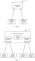
- This application provides a network architecture 100, including: a first network device and at least one second network device, where each of the second network devices communicates with the first network device.
- the first network device includes at least one port, and each of the second network devices communicates with one port of the first network device.
- Each of the second network devices is configured to send data, including clock information, time, a physical clock signal, and/or the like.
- the clock information includes information such as a clock level, indicating clock source quality.
- the clock information is clock information carried in an announce (Announce) packet sent by the second network device or clock information carried in a synchronization status message (synchronization status message, SSM) packet sent by the second network device.
- the time mentioned above is a time of the second network device for sending, and includes a time carried in a synchronization (Sync) packet sent by the second network device, a time carried in a Delay Resp packet sent by the second network device, and the like.
- Sync synchronization
- Delay Resp Delay Resp
- the second network device is directly connected to the first network device, or a link between the second network device and the first network device passes through at least one other network device, but each of the at least one other network device transparently transmits a packet between the first network device and the second network device.
- the second network device may be a clock source, or a network device through which a link between the first network device and a clock source passes.
- the first network device may receive clock information through each port of the first network device, and perform a clock source selection operation based on the clock information received by each port.
- the first network device selects a port after performing the clock source selection operation.
- the selected port is referred to as a first port
- a second network device communicating with the first port is referred to as a second network device 1.
- the clock source indicated by the clock information received by the first port may have highest quality.
- the state of the first port is a slave (Slave) state.
- the first network device receives a clock input signal through the first port in the slave state, where the clock input signal may include a time or a physical clock signal sent by the second network device 1, and adjusts a clock of the first network device based on the clock input signal, to achieve synchronization between a time of the clock of the first network device and a time of a clock of the second network device 1, or synchronization between a frequency of the clock of the first network device and a frequency of a clock of the second network device 1.
- the time of the second network device 1 for sending includes a time carried in a Sync packet sent by the second network device 1 and a time carried in a Delay Resp packet sent by the second network device 1.
- the first network device adjusts the clock of the first network device based on the time of the second network device 1 for sending, to achieve synchronization between the time of the clock of the first network device and the time of the clock of the second network device 1.
- the first network device receives, through the first port, a first Sync packet sent by the second network device 1, where the second network device 1 regularly or irregularly sends the Sync packet, the first Sync packet is a Sync packet currently sent by the second network device 1, and the first Sync packet includes a sending time Ta at which the second network device 1 sends the first Sync packet.
- the first network device obtains a receiving time Tb at which the first Sync packet is received, sends a first Delay Req packet to the second network device 1 through the first port, and obtains a sending time Tc at which the first Delay Req packet is sent.
- the first network device receives, through the first port, a first Delay Resp packet sent by the second network device 1 in response to the first Delay Req packet, where the first Delay Resp packet includes a receiving time Td at which the second network device 1 receives the first Delay Req packet.
- the first network device calculates a time offset between the first network device and the second network device 1 based on Ta, Tb, Tc, and/or Td, and adjusts the clock of the first network device based on the time offset.
- the first network device adjusts the clock of the first network device based on the physical clock signal, to achieve synchronization between the frequency of the clock of the first network device and the frequency of the clock of the second network device 1.
- the first network device includes a port 1 and a port 2, and the at least one second network device includes a second network device 1 and a second network device 2.
- the second network device 1 communicates with the port 1, and the second network device 2 communicates with the port 2.
- the first network device receives, through the port 1, clock information 1 sent by the second network device 1, and receives, through the port 2, clock information 2 sent by the second network device 2, and performs a clock source selection operation based on the clock information 1 and the clock information 2.
- the first network device receives a clock input signal through the port 1, where the clock input signal may be a time or a physical clock signal sent by the second network device 1, and adjusts the clock of the first network device based on the clock input signal, to implement time synchronization between the clock of the first network device and the clock of the second network device 1 or implement frequency synchronization between the clock of the first network device and the clock of the second network device 1.
- the clock input signal received by the first port may jump, causing the first network device to include tag information in the port attribute of the first port, and the tag information indicates that the first port is in a clock synchronization failed state.
- the first network device performs a clock source selection operation from ports excluding the first port, to reselect a port.
- the selected port is referred to as a second port
- a second network device communicating with the second port is referred to as a second network device 2.
- a state of the second port is a slave state, and a state of the first port changes to a non-slave state.
- the first network device receives a clock input signal through the second port, where the clock input signal includes a time or a physical clock signal sent by the second network device 2, and adjusts the clock of the first network device based on the received clock input signal.
- the tag information is a packet timing signal fail (packet timing signal fail, PTSF) tag.
- packet timing signal fail packet timing signal fail, PTSF
- That a clock input signal jumps means that, when the clock input signal is the time of the second network device 1 for sending, the time offset between the first network device and the second network device 1 obtained by the first network device based on the time sent of the second network device 1 for sending exceeds a time offset threshold; or when the clock input signal is the physical clock signal sent by the second network device 1, a phase difference between a phase of a physical clock signal received by the first port and a phase of a physical clock signal received last time exceeds a phase difference threshold.
- the first network device there may be a plurality of structures of the first network device.
- the following provides an example of the first network device. Refer to FIG. 2 .
- An embodiment of this application provides a first network device.
- the first network device is merely an example, and other examples are not enumerated.
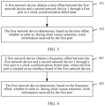
- the first network device includes a main control board and at least one interface board.
- the main control board communicates with each interface board, each interface board includes a plurality of ports, and each port on the interface board communicates with one second network device.
- the second network device sends data to the first network device, and the data includes clock information, a physical clock signal, and/or the like.
- each port on the interface board may receive clock information, the first network device performs, based on the clock information received by each port on the interface board, a clock source selection operation, and selects one port as a first port.
- the interface board sends the physical clock signal received by the first port to the main control board.
- the main control board may receive a physical clock signal sent by each interface board, select an optimal physical clock signal from the received physical clock signals, and adjust the clock of the first network device based on the best physical clock signal.
- the first network device includes the main control board, an interface board 1, and an interface board 2.
- the main control board separately communicates with the interface board 1 and the interface board 2.
- the interface board 1 includes a port 1 and a port 2
- the interface board 2 includes a port 3 and a port 4.
- the port 1 and the port 2 of the interface board 1 respectively communicate with the second network device 1 and the second network device 2
- the port 3 and the port 4 of the interface board 2 respectively communicate with a second network device 3 and a second network device 4.
- the port 1 of the interface board 1 receives clock information 1 sent by the second network device 1, and the port 2 of the interface board 1 receives clock information 2 sent by the second network device 2.
- the first network device performs a clock source selection operation based on the clock information 1 and the clock information 2. If the port 1 is selected, the interface board 1 sends the physical clock signal received by the port 1 to the main control board.
- the port 3 of the interface board 2 receives clock information 3 sent by the second network device 3, and the port 4 of the interface board 2 receives clock information 4 sent by the second network device 4.
- the first network device performs a clock source selection operation based on the clock information 3 and the clock information 4. If the port 3 is selected, the interface board 2 sends the physical clock signal received by the port 3 to the main control board.
- the main control board receives the physical clock signal sent by the interface board 1 and the physical clock signal sent by the interface board 2, selects a best physical clock signal from the two received physical clock signals, and adjusts the clock of the first network device based on the best physical clock signal.
- a phase of a physical clock signal received by a first interface on the interface board may jump.
- the first network device includes tag information in a port attribute of the first port, and the tag information indicates that the first port is in a clock synchronization failed state.
- the first network device performs a clock source selection operation on ports excluding the first port on the interface board to reselect a port.
- the selected port is referred to as a second port.
- the interface board sends a physical clock signal received by the second port to the main control board, so that the main control board adjusts the clock of the first network device based on the physical clock signal sent by each interface board.
- a reason why the clock input signal received by the first port jumps may be that the second network device 1 communicating with the first port fails, or a link between the first port and the second network device 1 fails, or the clock source fails in the case that the second network device 1 is a network device through which a link between the first port and a clock source passes.
- Technical personnel may recover the failure.
- the first network device performs a clock source selection operation based on any one of the following embodiments, and uses the clock information received by the first port as a reference object for selecting a clock source during clock source selection.
- the first network device may be a network element, for example, may be a device such as a switch, a router, a base station, a gateway, an optical transport network (optical transport network, OTN), an optical line terminal (optical line terminal, OLT), or an optical network unit (optical network unit, ONU).
- a network element for example, may be a device such as a switch, a router, a base station, a gateway, an optical transport network (optical transport network, OTN), an optical line terminal (optical line terminal, OLT), or an optical network unit (optical network unit, ONU).
- An embodiment of this application provides a method for selecting a clock source.
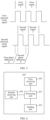
- the method can be applied to the network architecture 100 shown in FIG. 1 , and includes the following steps.
- Step 301 A first network device obtains a time offset between the first network device and a second network device 1 through a first port in a clock synchronization failed state.
- step 301 the first network device obtains the time offset by performing the following operations 3011 and 3012, which are as follows.
- the first network device obtains synchronization data between the first network device and the second network device through the first port, where a state of the first port is a first state.
- the first network device When the first network device detects that a clock input signal received by the first port jumps, the first network device may set the state of the first port to the first state, and the state of the first port being the first state remains unchanged.
- the first state includes a master (Master) state, a monitor (Monitor) state, or a passive (Passive) state. In this way, the first network device can obtain the synchronization data between the first network device and the second network device in real time through the first port in the first state.
- the first network device when the first network device detects that a clock input signal received by the first port jumps, the first network device sets the state of the first port to a master state, and then the first network device may periodically set the state of the first port to the first state.
- the first state includes a slave state, a monitor state, or a passive state.
- the first network device can periodically obtain the synchronization data between the first network device and the second network device through the first port in the first state. In this manner, load of the first network device can be reduced, and less network resources and computing resources of the first network device can be occupied.
- the first network device when the first network device detects that the clock input signal received by the first port jumps, the first network device may perform a clock source selection operation to select a second port.
- a state of the second port is the slave state.
- the first network device adjusts a clock of the first network device based on a clock input signal received by the second port, and the clock input signal includes a physical clock signal sent by a second network device 2 communicating with the second port or a time of the second network device 2 for sending.
- the first network device when a clock input signal received by the port 1 jumps, the first network device includes tag information in a port attribute of the port 1, and the tag information marks that the port 1 is in the clock synchronization failed state.
- the first network device performs a clock source selection operation, and selects a port 2.
- a state of the port 2 changes to the slave state.
- the first network device adjusts the clock of the first network device based on the clock input signal received by the port 2.
- the first network device obtains the synchronization data between the first network device and the second network device 1 by performing the following operations (1) to (3), which are as follows.
- the second network device 1 regularly or irregularly sends a Sync packet, and the second Sync packet is a Sync packet currently sent by the second network device 1.
- the first network device may receive, through the first port, the second Sync packet sent by the second network device 1.
- the first network device sends a second Delay _Req packet to the second network device 1, and determines a sending time T3 at which the second Delay _Req packet is sent.
- the first network device sends the second Delay _Req packet to the second network device 1 through the first port in the first state.
- the first state When the state of the first port remains the first state, the first state includes a master state, a monitor state, or a passive state.
- the master state When the first state is the master state, the master state is different from a master state defined in the existing standard, and the first port in the master state can send the second Delay Req packet to the second network device 1, and receive a second Delay _Resp packet sent by the second network device 1 in response to the second Delay_Req packet.
- the first state is the monitor state or the passive state
- the first port in the monitor state or the passive state can send the second Delay _Req packet to the second network device 1, and receive a second Delay _Resp packet sent by the second network device 1 in response to the second Delay _Req packet.
- the first state When the state of the first port is periodically set to the first state, the first state includes a slave state, a monitor state, or a passive state.
- the first network device detects that the clock input signal received by the first port jumps, the first network device sets the state of the first port to the master state, and the first port in the master state cannot send the second Delay _Req packet to the second network device 1 and receive the second Delay _Resp packet sent by the second network device 1 in response to the second Delay _Req packet.
- the state of the first port needs to be set to the first state.
- the state of the second port of the first network device may still be the slave state, and the first network device still adjusts the clock of the first network device based on the clock input signal received by the second port.
- the first state is the slave state, that is, when the first network device sets the state of the first port to the slave state
- the state of the second port may not be the slave state.
- the first network device needs to control the clock of the first network device not to be adjusted based on the clock input signal received by the first port. Therefore, the following case is avoided: The time offset between the first network device and the second network device 1 cannot be accurately obtained because the clock of the first network device is synchronized with the second network device 1.
- the first network device receives a second Delay_Resp packet sent by the second network device 1, where the second Delay _Resp packet includes a receiving time T4 at which the second network device 1 receives the second Delay _Req packet.
- the first network device receives, through the first port, the second Delay _Resp packet sent by the second network device 1, where the synchronization data includes several of T1, T2, T3, and T4.
- the first network device obtains the time offset between the first network device and the second network device 1 based on the synchronization data.
- the time offset is equal to [(T2-T1)-(T4-T3)]/2, or the time offset is equal to T4-T3-delay, or the time offset is equal to T4-T3.
- delay is a delay between the first network device and the second network device 1, and is based on a length of a link between the first network device and the second network device 1.
- the length of the link may be preconfigured for the first network device.
- the link may be optical fibers or the like.
- Step 302 The first network device determines, based on the time offset, whether to refer to, during clock source selection, clock information received by the first port.
- the first network device determines that the clock input signal received by the first port recovers, that is, the clock input signal does not jump any more, and refers to, during clock source selection, the clock information received by the first port.
- the first network device may perform a clock source selection operation based on the clock information received by the first port and clock information received by another port on the first network device. That is, the clock information received by the first port is referred to during clock source selection. After the clock source selection operation is performed, a port is selected, and a state of the selected port changes to the slave state. The first network device adjusts a clock of the first network device based on the clock input signal received by the selected port.
- the first network device when the time offset is less than the time offset threshold, the first network device further sets the tag information to indicate that the first port is in a clock synchronization normal state.
- the first network device can automatically obtain the time offset between the first network device and the second network device through the first port in the clock synchronization failed state, it may be determined, based on the time offset, that the clock input signal received by the first port recovers, that is, the clock input signal does not jump any more, and the clock information received by the first port is referred to during clock source selection.
- the first network device can automatically detect the situation, and use the first port as a reference object during clock source selection, to timely and automatically select a clock source with higher quality for synchronization, thereby improving operation and maintenance efficiency.
- the first network device controls the clock of the first network device not to be adjusted based on the clock input signal received by the first port. Therefore, the following case can be avoided: The time offset between the first network device and the second network device 1 cannot be accurately obtained because the clock of the first network device is synchronized with the second network device 1, thereby improving accuracy of determining that the clock input signal received by the first port recovers.
- An embodiment of this application provides a method for selecting a clock source.
- the method can be applied to the network architecture 100 shown in FIG. 2 , and may be performed by the first network device shown in FIG. 2 .
- the method includes the following steps.
- Step 401 A first network device obtains a frequency offset between the first network device and a second network device 1 through a first port in a clock synchronization failed state, and the first port is located on an interface board of the first network device.
- step 401 when the first network device detects that a physical clock signal received by the first port on the interface board jumps, the first network device may perform a clock source selection operation, and select a second port from ports excluding the first port on the interface board.
- the interface board sends a physical clock signal received by the second port to a main control board of the first network device. That a physical clock signal jumps means that a phase difference between a phase of a physical clock signal received by the first port and a phase of a physical clock signal received by the first port last time exceeds a phase difference threshold.
- the interface board may periodically send the physical clock signal received by the first port to the main control board of the first network device.
- the physical clock signal received by the first port is referred to as a first physical clock signal
- the first physical clock signal is sent by the second network device 1 communicating with the first port.
- the interface board stops sending, to the main control board of the first network device, the physical clock signal received by the second port.
- the main control board of the first network device receives the first physical clock signal, and obtains the frequency offset between the first network device and the second network device 1 based on the first physical clock signal and a second physical clock signal.
- the second physical clock signal is a local signal of the first network device.
- an operation of obtaining the frequency offset between the first network device and the second network device 1 is as follows.
- the first physical clock signal includes a plurality of consecutive first signals
- the second physical clock signal includes a plurality of consecutive second signals
- each first signal corresponds to one second signal.
- the first network device selects two adjacent first signals from the first physical clock signal.
- the two first signals are referred to as a first signal 1 and a first signal 2.
- the first signal 1 is earlier than the first signal 2
- the second physical clock signal includes a second signal 1 corresponding to the first signal 1 and a second signal 2 corresponding to the first signal 2.
- the interface board 1 sends the physical clock signal received by the port 1 to the main control board, and the interface board 1 further detects the physical clock signal received by the port 1.
- the first network device may perform a clock source selection operation, and reselect a port 2 from ports excluding the port 1 on the interface board 1.
- the interface board 1 sends the physical clock signal received by the port 2 to the main control board of the first network device.
- the interface board 1 may periodically send the physical clock signal received by the port 1 to the main control board of the first network device.
- the first physical clock signal is the physical clock signal that is sent by the second network device 1 and that is received by the port 1.
- the interface board 1 stops sending, to the main control board of the first network device, the physical clock signal received by the port 2.
- the main control board of the first network device receives the first physical clock signal, and calculates the frequency offset between the first network device and the second network device 1 based on the first physical clock signal and the local second physical clock signal.
- the first network device controls the clock of the first network device not to be adjusted based on the first physical clock signal. Therefore, the following case can be avoided: The frequency offset between the first network device and the second network device 1 cannot be accurately calculated because the clock of the first network device is synchronized with the second network device 1 communicating with the first port.
- Step 402 The first network device determines, based on the frequency offset, whether to refer to, during clock source selection, the clock information received by the first port.
- the first network device determines that the first physical clock signal received by the first port recovers, that is, the frequency of the first physical clock signal does not jump, and refers to the clock information received by the first port during clock source selection in the interface board on which the first port is located.
- the first network device may perform a clock source selection operation based on the clock information received by the first port and clock information received by another port on the interface board. That is, the clock information received by the first port is referred to during clock source selection.
- a port is selected, and the interface board sends the physical clock signal received by the selected port to the main control board of the first network device.
- the main control board of the first network device selects an optimal physical clock signal from physical clock signals sent by interface boards in the first network device, and adjusts the clock of the first network device based on the optimal physical clock signal.
- the first network device sets the tag information to indicate that the first port is in a clock synchronization normal state.
- the first network device can automatically obtain the frequency offset between the first network device and the second network device 1 through the first port in the clock synchronization failed state, it may be determined, based on the frequency offset, that the physical clock signal received by the first port recovers, that is, the physical clock signal does not jump, and the clock information received by the first port is referred to during clock source selection.
- the first network device can automatically detect the situation, and use the first port as a reference object during clock source selection, to timely select a clock source with higher quality for synchronization, thereby improving operation and maintenance efficiency.
- the first network device further controls the clock of the first network device not to be adjusted based on the first physical clock signal. Therefore, the following case can be avoided:
- the frequency offset between the first network device and the second network device 1 cannot be accurately calculated because the clock of the first network device is synchronized with the second network device 1 communicating with the first port. This can improve accuracy of determining that the physical clock signal received by the first port recovers.
- An embodiment of this application provides an apparatus 600 for selecting a clock source.
- the apparatus 600 may be deployed on the first network device in any one of the foregoing embodiments.
- the apparatus 600 is deployed on the first network device in the network architecture 100 shown in FIG. 1 or FIG. 2 , or deployed on the first network device in the method shown in FIG. 3 , or deployed on the first network device in the method shown in FIG. 4 .
- the apparatus 600 includes: a processing unit 601, configured to obtain synchronization offset data between the apparatus 600 and a second network device through a first port in a clock synchronization failed state.
- the processing unit 601 is further configured to determine, based on the synchronization offset data, whether to refer to, during clock source selection, the clock information received by the first port.
- the synchronization offset data obtained by the processing unit 601 may be a time offset or a frequency offset.
- the time offset by the processing unit 601 refers to related content in step 301 in the embodiment shown in FIG. 3 . Details are not described herein again.
- the frequency offset by the processing unit 601 refer to related content in step 401 in the embodiment shown in FIG. 4 . Details are not described herein again.
- the processing unit 601 is configured to, when the synchronization offset data is less than an offset threshold, refer to the clock information received by the first port during clock source selection.
- step 302 in the embodiment shown in FIG. 3 or step 402 in the embodiment shown in FIG. 4 . Details are not described herein again.
- a port attribute of the first port includes tag information, and the tag information indicates that the first port is in a clock synchronization failed state.
- the processing unit 601 is further configured to set, when the synchronization offset data is less than the offset threshold, the tag information to indicate that the first port is in a clock synchronization normal state.
- processing unit 601 is configured to:
- the first state includes a slave Slave state, a master Master state, a monitor Monitor state, or a passive Passive state.
- processing unit 601 is further configured to set the state of the first port to the first state.
- the processing unit 601 is configured to: periodically set the state of the first port to the first state, where the first state includes a slave state, a monitor state, or a passive state.
- the processing unit 601 is configured to, when the first state is a slave state, control a clock of the apparatus 600 not to be adjusted based on a clock input signal of the first port.
- the apparatus 600 further includes a first receiving unit 602 and a sending unit 603.
- the first receiving unit 602 is configured to receive a synchronization Sync packet sent by the second network device, where the Sync packet includes a sending time T1 at which the second network device sends the Sync packet.
- the processing unit 601 is configured to determine a receiving time T2 at which the Sync packet is received.
- the sending unit 603 is configured to send a delay request Delay _Req packet to the second network device.
- the processing unit 601 is further configured to determine a sending time T3 at which a Delay _Req packet is sent.
- the first receiving unit 602 is further configured to receive a delay response Delay _Resp packet sent by the second network device, where the Delay _Resp packet includes a receiving time T4 at which the second network device receives the Delay _Req packet, and the synchronization data includes several of T1, T2, T3, and T4.
- the synchronization offset data includes a time offset between the apparatus 600 and the second network device.
- the apparatus 600 further includes a second receiving unit 604.
- the second receiving unit 604 is configured to receive, through the first port, a first physical clock signal sent by the second network device.
- the processing unit 601 is configured to obtain a frequency offset between the apparatus and a second network device based on the first physical clock signal and a second physical clock signal, where the second physical clock signal is a local signal of the apparatus 600.
- the processing unit 601 is further configured to control the clock of the apparatus 600 not to be adjusted based on the first physical clock signal.
- the processing unit automatically obtains the synchronization offset data between the first network device and the second network device through the first port in the clock synchronization failed state, and determines, based on the synchronization offset data, whether the clock input signal received by the first port recovers.
- the processing unit refers to the clock information received by the first port during clock source selection. In this way, after the second network device communicating with the first port, the clock source, or the link connected to the first port is recovered from a failure, the processing unit automatically detects the situation, and uses the first port as a reference object during clock source selection, to timely and automatically select a clock source with higher quality for synchronization, thereby improving operation and maintenance efficiency.
- An embodiment of this application provides a schematic diagram of an apparatus 700 for selecting a clock source.
- the apparatus 700 may be the first network device in any one of the foregoing embodiments.
- the apparatus 700 is the first network device in the network architecture 100 shown in FIG. 1 or FIG. 2 , or the first network device in the method shown in FIG. 3 , or the first network device in the method shown in FIG. 4 .
- the apparatus 700 includes at least one processor 701, an internal connection 702, a memory 703, and at least one transceiver 704.
- the apparatus 700 is an apparatus of a hardware structure, and may be configured to implement functional modules in the apparatus 600 in FIG. 6 .
- the processing unit 601 in the apparatus 600 shown in FIG. 6 may be implemented by the at least one processor 701 by calling code in the memory 703, and the first receiving unit 602, the sending unit 603, and the second receiving unit 604 in the apparatus 600 shown in FIG. 6 may be implemented by the transceiver 704.
- the apparatus 700 may further be configured to implement functions of the first network device in any one of the foregoing embodiments.
- the processor 701 may be a general-purpose central processing unit (central processing unit, CPU), a network processor (network processor, NP), a microprocessor, an application-specific integrated circuit (application-specific integrated circuit, ASIC), or one or more integrated circuits configured to control program execution of solutions of this application.
- CPU central processing unit
- NP network processor
- ASIC application-specific integrated circuit
- the internal connection 702 may include a channel for transmitting information between the foregoing components.
- the internal connection 702 is a board, a bus, or the like.
- the transceiver 704 is configured to communicate with another device or a communication network.
- the memory 703 may be a read-only memory (read-only memory, ROM) or another type of static storage device that can store static information and instructions, or a random access memory (random access memory, RAM) or another type of dynamic storage device that can store information and instructions; or may be an electrically erasable programmable read-only memory (electrically erasable programmable read-only memory, EEPROM), a compact disc read-only memory (compact disc read-only memory, CD-ROM) or another optical disc storage, an optical disc storage (including a compact optical disc, a laser disc, an optical disc, a digital versatile disc, a Blu-ray disc, or the like), a magnetic disk storage medium or another magnetic storage device, or any other medium that can be configured to carry or store expected program code in a form of instructions or a data structure and that can be accessed by a computer, but is not limited thereto.
- the memory may exist independently, and is connected to the processor through the bus. The memory may alternatively be integrated with the processor.
- the memory 703 is configured to store application program code for executing the solutions in this application, and the processor 701 controls execution.
- the processor 701 is configured to execute the application program code stored in the memory 703, and cooperate with the at least one transceiver 704, so that the apparatus 700 implements functions in the method in this patent.
- the processor 701 may include one or more CPUs, for example, a CPU 0 and a CPU 1 in FIG. 7 .
- the apparatus 700 may include a plurality of processors, for example, the processor 701 and a processor 707 shown in FIG. 7 .
- Each of the processors may be a single-core (single-CPU) processor, or may be a multi-core (multi-CPU) processor.
- the processor herein may be one or more devices, circuits, and/or processing cores configured to process data (for example, computer program instructions).
- the program may be stored in a computer-readable storage medium.
- the storage medium may be a read-only memory, a magnetic disk, an optical disc, or the like.
Landscapes
- Engineering & Computer Science (AREA)
- Computer Networks & Wireless Communication (AREA)
- Signal Processing (AREA)
- Synchronisation In Digital Transmission Systems (AREA)
Applications Claiming Priority (2)
| Application Number | Priority Date | Filing Date | Title |
|---|---|---|---|
| CN202011507206.5A CN114650113B (zh) | 2020-12-18 | 2020-12-18 | 选择时钟源的方法及装置 |
| PCT/CN2021/139372 WO2022127924A1 (zh) | 2020-12-18 | 2021-12-17 | 选择时钟源的方法及装置 |
Publications (3)
| Publication Number | Publication Date |
|---|---|
| EP4254831A1 true EP4254831A1 (de) | 2023-10-04 |
| EP4254831A4 EP4254831A4 (de) | 2024-08-28 |
| EP4254831B1 EP4254831B1 (de) | 2025-12-03 |
Family
ID=81989925
Family Applications (1)
| Application Number | Title | Priority Date | Filing Date |
|---|---|---|---|
| EP21905846.8A Active EP4254831B1 (de) | 2020-12-18 | 2021-12-17 | Verfahren und vorrichtung zur auswahl einer taktquelle |
Country Status (6)
| Country | Link |
|---|---|
| US (1) | US20230362854A1 (de) |
| EP (1) | EP4254831B1 (de) |
| JP (1) | JP2023554065A (de) |
| KR (1) | KR20230119215A (de) |
| CN (1) | CN114650113B (de) |
| WO (1) | WO2022127924A1 (de) |
Families Citing this family (4)
| Publication number | Priority date | Publication date | Assignee | Title |
|---|---|---|---|---|
| CN114448548B (zh) * | 2019-09-06 | 2024-11-15 | 华为技术有限公司 | 用于实现时钟源选取的方法、装置、系统及存储介质 |
| CN117495350B (zh) * | 2023-11-06 | 2024-05-24 | 烟台持久钟表有限公司 | 一种基于钟联网的时钟运维方法、系统、设备和存储介质 |
| US20250212145A1 (en) * | 2023-12-20 | 2025-06-26 | Cisco Technology Inc. | Clock Quality Measurements and Monitoring in 5G Network |
| US20250211351A1 (en) * | 2023-12-20 | 2025-06-26 | Cisco Technology Inc. | System and Method to Dynamically Maintain Mutually Traceable Clocks of Different Types |
Family Cites Families (24)
| Publication number | Priority date | Publication date | Assignee | Title |
|---|---|---|---|---|
| JPH06104882A (ja) * | 1992-09-22 | 1994-04-15 | Matsushita Electric Ind Co Ltd | 網同期クロック供給装置 |
| US6754171B1 (en) * | 2000-05-18 | 2004-06-22 | Enterasys Networks, Inc. | Method and system for distributed clock failure protection in a packet switched network |
| JP4709909B2 (ja) * | 2009-01-28 | 2011-06-29 | 株式会社東芝 | 変換装置 |
| SG178498A1 (en) * | 2009-08-21 | 2012-04-27 | Aviat Networks Inc | Synchronization distribution in microwave backhaul networks |
| CN102006135A (zh) * | 2010-12-03 | 2011-04-06 | 北京华环电子股份有限公司 | 一种选择同步时钟源的方法及装置 |
| CN102263630B (zh) * | 2011-07-21 | 2017-06-16 | 中兴通讯股份有限公司 | 一种时钟源的选择方法 |
| JP5746081B2 (ja) * | 2012-03-28 | 2015-07-08 | 日本電信電話株式会社 | クロック供給方法およびクロック供給装置 |
| US9310832B2 (en) * | 2012-10-30 | 2016-04-12 | National Instruments Corporation | Backplane clock synchronization |
| WO2014067470A1 (en) * | 2012-10-31 | 2014-05-08 | Hangzhou H3C Technologies Co., Ltd. | Port mode synchronization between switches |
| US9654242B2 (en) * | 2013-04-18 | 2017-05-16 | Telefonaktiebolaget Lm Ericsson (Publ) | Node and method for selecting synchronization source |
| CN105024798A (zh) * | 2014-04-28 | 2015-11-04 | 中兴通讯股份有限公司 | 一种时间同步的方法及装置 |
| US9270395B2 (en) * | 2014-05-05 | 2016-02-23 | Telefonaktiebolaget L M Ericsson (Publ) | Method for robust PTP synchronization with default 1588V2 profile |
| CN104579534B (zh) * | 2014-12-31 | 2017-10-10 | 北京东土科技股份有限公司 | 一种sdh网络中的时钟同步方法及系统 |
| JP5937243B1 (ja) * | 2015-02-17 | 2016-06-22 | 日本電信電話株式会社 | 時刻同期方法および時刻同期装置 |
| US11122531B2 (en) * | 2016-06-09 | 2021-09-14 | Google Llc | Mitigating interference between neighboring cellular communications |
| CN113328820B (zh) * | 2016-12-30 | 2022-09-16 | 华为技术有限公司 | 交互时间同步报文的方法以及网络装置 |
| US10986015B2 (en) * | 2018-05-24 | 2021-04-20 | Quanta Computer Inc. | Micro server built-in switch uplink port backup mechanism |
| CN111385050B (zh) * | 2018-12-29 | 2022-11-08 | 华为技术有限公司 | 时钟同步方法、装置和存储介质 |
| JP2020188401A (ja) * | 2019-05-16 | 2020-11-19 | 富士通株式会社 | クロック同期プログラム、クロック同期方法、通信装置、及び通信システム |
| CN114448548B (zh) * | 2019-09-06 | 2024-11-15 | 华为技术有限公司 | 用于实现时钟源选取的方法、装置、系统及存储介质 |
| CN113078976A (zh) * | 2020-01-06 | 2021-07-06 | 华为技术有限公司 | 一种时钟端口属性恢复方法、设备及系统 |
| GB2595885B (en) * | 2020-06-09 | 2022-11-09 | Canon Kk | Method and apparatus for synchronizing different communication ports |
| CN114258125A (zh) * | 2020-09-25 | 2022-03-29 | 华为技术有限公司 | 处理时间同步故障的方法、装置及系统 |
| MX2023009649A (es) * | 2021-02-18 | 2023-08-24 | Arris Entpr Llc | Sistemas y metodos para soportar los ajustes de fase a traves de docsis. |
-
2020
- 2020-12-18 CN CN202011507206.5A patent/CN114650113B/zh active Active
-
2021
- 2021-12-17 KR KR1020237024243A patent/KR20230119215A/ko not_active Withdrawn
- 2021-12-17 WO PCT/CN2021/139372 patent/WO2022127924A1/zh not_active Ceased
- 2021-12-17 JP JP2023536583A patent/JP2023554065A/ja active Pending
- 2021-12-17 EP EP21905846.8A patent/EP4254831B1/de active Active
-
2023
- 2023-06-16 US US18/336,891 patent/US20230362854A1/en active Pending
Also Published As
| Publication number | Publication date |
|---|---|
| JP2023554065A (ja) | 2023-12-26 |
| CN114650113A (zh) | 2022-06-21 |
| US20230362854A1 (en) | 2023-11-09 |
| KR20230119215A (ko) | 2023-08-16 |
| WO2022127924A1 (zh) | 2022-06-23 |
| EP4254831A4 (de) | 2024-08-28 |
| CN114650113B (zh) | 2024-07-16 |
| EP4254831B1 (de) | 2025-12-03 |
Similar Documents
| Publication | Publication Date | Title |
|---|---|---|
| EP4254831B1 (de) | Verfahren und vorrichtung zur auswahl einer taktquelle | |
| US11444747B2 (en) | Measure and improve clock synchronization using combination of transparent and boundary clocks | |
| CA2675645C (en) | Facilitating synchronization of servers in a coordinated timing network | |
| US9112626B2 (en) | Employing configuration information to determine the role of a server in a coordinated timing network | |
| US20120079310A1 (en) | Communication system, communication interface, and synchronization method | |
| EP3352392B1 (de) | Verarbeitungsverfahren und -vorrichtung für zeitsynchronisationspakete | |
| US12149603B2 (en) | Clock port attribute recovery method, device, and system | |
| US20230262625A1 (en) | Time Synchronization Fault Processing Method, Apparatus, And System | |
| EP4418602B1 (de) | Übertragungsvorrichtung und zeitsynchronisationssystem | |
| CN110620630B (zh) | 时间同步方法、装置、网络设备及计算机可读存储介质 | |
| EP0748547B1 (de) | Hierarchisches synchronisierungsverfahren | |
| CN118316562B (zh) | 一种双模通信模块的时钟同步方法 | |
| CN110266422B (zh) | 中间时钟设备报文驻留时间处理方法、装置、设备及介质 | |
| EP4192137A1 (de) | Verfahren, vorrichtung und system zur verarbeitung von zeitsynchronisationsfehlern und speichermedium | |
| CN107947888A (zh) | 一种基于网络通信的任务级同步方法 | |
| CN103259639B (zh) | 一种堆叠设备的时钟同步方法和设备 | |
| CN106712887B (zh) | 一种基于网络时钟协议的主从双机状态同步方法 | |
| JP2024521137A (ja) | クロックソース選択方法、装置、及びシステム、並びに記憶媒体 | |
| CN101511098A (zh) | 一种分布式网元任务管理系统及方法 | |
| EP4651512A1 (de) | Verbindungsumschaltverfahren und -system sowie elektronische vorrichtung und speichermedium | |
| CN101601251A (zh) | 定义协调定时网络中的层-1配置 | |
| CN118826940A (zh) | 时钟同步方法、设备及介质 | |
| CN118282550A (zh) | 一种时钟源的确定方法、网络设备及网络管理设备 | |
| CN113534887A (zh) | 基于实时总线的板卡间时间同步方法、装置和电子设备 | |
| CN118740303A (zh) | 时间调整方法、光纤链路检测方法及装置、电子设备 |
Legal Events
| Date | Code | Title | Description |
|---|---|---|---|
| STAA | Information on the status of an ep patent application or granted ep patent |
Free format text: STATUS: THE INTERNATIONAL PUBLICATION HAS BEEN MADE |
|
| PUAI | Public reference made under article 153(3) epc to a published international application that has entered the european phase |
Free format text: ORIGINAL CODE: 0009012 |
|
| STAA | Information on the status of an ep patent application or granted ep patent |
Free format text: STATUS: REQUEST FOR EXAMINATION WAS MADE |
|
| 17P | Request for examination filed |
Effective date: 20230629 |
|
| AK | Designated contracting states |
Kind code of ref document: A1 Designated state(s): AL AT BE BG CH CY CZ DE DK EE ES FI FR GB GR HR HU IE IS IT LI LT LU LV MC MK MT NL NO PL PT RO RS SE SI SK SM TR |
|
| DAV | Request for validation of the european patent (deleted) | ||
| DAX | Request for extension of the european patent (deleted) | ||
| A4 | Supplementary search report drawn up and despatched |
Effective date: 20240726 |
|
| RIC1 | Information provided on ipc code assigned before grant |
Ipc: H04J 3/14 20060101ALI20240722BHEP Ipc: H04J 3/06 20060101AFI20240722BHEP |
|
| GRAP | Despatch of communication of intention to grant a patent |
Free format text: ORIGINAL CODE: EPIDOSNIGR1 |
|
| STAA | Information on the status of an ep patent application or granted ep patent |
Free format text: STATUS: GRANT OF PATENT IS INTENDED |
|
| INTG | Intention to grant announced |
Effective date: 20250711 |
|
| GRAS | Grant fee paid |
Free format text: ORIGINAL CODE: EPIDOSNIGR3 |
|
| GRAA | (expected) grant |
Free format text: ORIGINAL CODE: 0009210 |
|
| STAA | Information on the status of an ep patent application or granted ep patent |
Free format text: STATUS: THE PATENT HAS BEEN GRANTED |
|
| AK | Designated contracting states |
Kind code of ref document: B1 Designated state(s): AL AT BE BG CH CY CZ DE DK EE ES FI FR GB GR HR HU IE IS IT LI LT LU LV MC MK MT NL NO PL PT RO RS SE SI SK SM TR |
|
| REG | Reference to a national code |
Ref country code: CH Ref legal event code: F10 Free format text: ST27 STATUS EVENT CODE: U-0-0-F10-F00 (AS PROVIDED BY THE NATIONAL OFFICE) Effective date: 20251203 Ref country code: GB Ref legal event code: FG4D |
|
| REG | Reference to a national code |
Ref country code: DE Ref legal event code: R096 Ref document number: 602021043890 Country of ref document: DE |
|
| REG | Reference to a national code |
Ref country code: IE Ref legal event code: FG4D |
|
| PGFP | Annual fee paid to national office [announced via postgrant information from national office to epo] |
Ref country code: DE Payment date: 20251216 Year of fee payment: 5 |
|
| PGFP | Annual fee paid to national office [announced via postgrant information from national office to epo] |
Ref country code: GB Payment date: 20251211 Year of fee payment: 5 |
|
| PGFP | Annual fee paid to national office [announced via postgrant information from national office to epo] |
Ref country code: AT Payment date: 20260113 Year of fee payment: 5 |
|
| REG | Reference to a national code |
Ref country code: NL Ref legal event code: MP Effective date: 20251203 |
|
| PG25 | Lapsed in a contracting state [announced via postgrant information from national office to epo] |
Ref country code: ES Free format text: LAPSE BECAUSE OF FAILURE TO SUBMIT A TRANSLATION OF THE DESCRIPTION OR TO PAY THE FEE WITHIN THE PRESCRIBED TIME-LIMIT Effective date: 20251203 |
|
| REG | Reference to a national code |
Ref country code: LT Ref legal event code: MG9D |
|
| PG25 | Lapsed in a contracting state [announced via postgrant information from national office to epo] |
Ref country code: NO Free format text: LAPSE BECAUSE OF FAILURE TO SUBMIT A TRANSLATION OF THE DESCRIPTION OR TO PAY THE FEE WITHIN THE PRESCRIBED TIME-LIMIT Effective date: 20260303 |
|
| PG25 | Lapsed in a contracting state [announced via postgrant information from national office to epo] |
Ref country code: HR Free format text: LAPSE BECAUSE OF FAILURE TO SUBMIT A TRANSLATION OF THE DESCRIPTION OR TO PAY THE FEE WITHIN THE PRESCRIBED TIME-LIMIT Effective date: 20251203 Ref country code: FI Free format text: LAPSE BECAUSE OF FAILURE TO SUBMIT A TRANSLATION OF THE DESCRIPTION OR TO PAY THE FEE WITHIN THE PRESCRIBED TIME-LIMIT Effective date: 20251203 |
|
| PG25 | Lapsed in a contracting state [announced via postgrant information from national office to epo] |
Ref country code: RS Free format text: LAPSE BECAUSE OF FAILURE TO SUBMIT A TRANSLATION OF THE DESCRIPTION OR TO PAY THE FEE WITHIN THE PRESCRIBED TIME-LIMIT Effective date: 20260303 |
|
| PG25 | Lapsed in a contracting state [announced via postgrant information from national office to epo] |
Ref country code: PL Free format text: LAPSE BECAUSE OF FAILURE TO SUBMIT A TRANSLATION OF THE DESCRIPTION OR TO PAY THE FEE WITHIN THE PRESCRIBED TIME-LIMIT Effective date: 20251203 |
|
| PG25 | Lapsed in a contracting state [announced via postgrant information from national office to epo] |
Ref country code: LV Free format text: LAPSE BECAUSE OF FAILURE TO SUBMIT A TRANSLATION OF THE DESCRIPTION OR TO PAY THE FEE WITHIN THE PRESCRIBED TIME-LIMIT Effective date: 20251203 |