EP4256178B1 - Abgasturbolader mit katalysator und einen solchen aufweisendes hybridfahrzeug - Google Patents
Abgasturbolader mit katalysator und einen solchen aufweisendes hybridfahrzeug Download PDFInfo
- Publication number
- EP4256178B1 EP4256178B1 EP21820165.5A EP21820165A EP4256178B1 EP 4256178 B1 EP4256178 B1 EP 4256178B1 EP 21820165 A EP21820165 A EP 21820165A EP 4256178 B1 EP4256178 B1 EP 4256178B1
- Authority
- EP
- European Patent Office
- Prior art keywords
- exhaust gas
- turbocharger
- turbine
- substrate block
- catalyst substrate
- Prior art date
- Legal status (The legal status is an assumption and is not a legal conclusion. Google has not performed a legal analysis and makes no representation as to the accuracy of the status listed.)
- Active
Links
Images


Classifications
-
- F—MECHANICAL ENGINEERING; LIGHTING; HEATING; WEAPONS; BLASTING
- F01—MACHINES OR ENGINES IN GENERAL; ENGINE PLANTS IN GENERAL; STEAM ENGINES
- F01D—NON-POSITIVE DISPLACEMENT MACHINES OR ENGINES, e.g. STEAM TURBINES
- F01D9/00—Stators
- F01D9/02—Nozzles; Nozzle boxes; Stator blades; Guide conduits, e.g. individual nozzles
- F01D9/026—Scrolls for radial machines or engines
-
- F—MECHANICAL ENGINEERING; LIGHTING; HEATING; WEAPONS; BLASTING
- F02—COMBUSTION ENGINES; HOT-GAS OR COMBUSTION-PRODUCT ENGINE PLANTS
- F02B—INTERNAL-COMBUSTION PISTON ENGINES; COMBUSTION ENGINES IN GENERAL
- F02B37/00—Engines characterised by provision of pumps driven at least for part of the time by exhaust
- F02B37/02—Gas passages between engine outlet and pump drive, e.g. reservoirs
- F02B37/025—Multiple scrolls or multiple gas passages guiding the gas to the pump drive
-
- F—MECHANICAL ENGINEERING; LIGHTING; HEATING; WEAPONS; BLASTING
- F01—MACHINES OR ENGINES IN GENERAL; ENGINE PLANTS IN GENERAL; STEAM ENGINES
- F01D—NON-POSITIVE DISPLACEMENT MACHINES OR ENGINES, e.g. STEAM TURBINES
- F01D15/00—Adaptations of machines or engines for special use; Combinations of engines with devices driven thereby
- F01D15/02—Adaptations for driving vehicles, e.g. locomotives
-
- F—MECHANICAL ENGINEERING; LIGHTING; HEATING; WEAPONS; BLASTING
- F01—MACHINES OR ENGINES IN GENERAL; ENGINE PLANTS IN GENERAL; STEAM ENGINES
- F01N—GAS-FLOW SILENCERS OR EXHAUST APPARATUS FOR MACHINES OR ENGINES IN GENERAL; GAS-FLOW SILENCERS OR EXHAUST APPARATUS FOR INTERNAL-COMBUSTION ENGINES
- F01N3/00—Exhaust or silencing apparatus having means for purifying, rendering innocuous, or otherwise treating exhaust
- F01N3/08—Exhaust or silencing apparatus having means for purifying, rendering innocuous, or otherwise treating exhaust for rendering innocuous
- F01N3/10—Exhaust or silencing apparatus having means for purifying, rendering innocuous, or otherwise treating exhaust for rendering innocuous by thermal or catalytic conversion of noxious components of exhaust
- F01N3/24—Exhaust or silencing apparatus having means for purifying, rendering innocuous, or otherwise treating exhaust for rendering innocuous by thermal or catalytic conversion of noxious components of exhaust characterised by constructional aspects of converting apparatus
- F01N3/28—Construction of catalytic reactors
- F01N3/2882—Catalytic reactors combined or associated with other devices, e.g. exhaust silencers or other exhaust purification devices
-
- F—MECHANICAL ENGINEERING; LIGHTING; HEATING; WEAPONS; BLASTING
- F01—MACHINES OR ENGINES IN GENERAL; ENGINE PLANTS IN GENERAL; STEAM ENGINES
- F01N—GAS-FLOW SILENCERS OR EXHAUST APPARATUS FOR MACHINES OR ENGINES IN GENERAL; GAS-FLOW SILENCERS OR EXHAUST APPARATUS FOR INTERNAL-COMBUSTION ENGINES
- F01N2340/00—Dimensional characteristics of the exhaust system, e.g. length, diameter or volume of the exhaust apparatus; Spatial arrangements of exhaust apparatuses
-
- F—MECHANICAL ENGINEERING; LIGHTING; HEATING; WEAPONS; BLASTING
- F01—MACHINES OR ENGINES IN GENERAL; ENGINE PLANTS IN GENERAL; STEAM ENGINES
- F01N—GAS-FLOW SILENCERS OR EXHAUST APPARATUS FOR MACHINES OR ENGINES IN GENERAL; GAS-FLOW SILENCERS OR EXHAUST APPARATUS FOR INTERNAL-COMBUSTION ENGINES
- F01N2340/00—Dimensional characteristics of the exhaust system, e.g. length, diameter or volume of the exhaust apparatus; Spatial arrangements of exhaust apparatuses
- F01N2340/06—Arrangement of the exhaust apparatus relative to the turbine of a turbocharger
-
- F—MECHANICAL ENGINEERING; LIGHTING; HEATING; WEAPONS; BLASTING
- F05—INDEXING SCHEMES RELATING TO ENGINES OR PUMPS IN VARIOUS SUBCLASSES OF CLASSES F01-F04
- F05D—INDEXING SCHEME FOR ASPECTS RELATING TO NON-POSITIVE-DISPLACEMENT MACHINES OR ENGINES, GAS-TURBINES OR JET-PROPULSION PLANTS
- F05D2220/00—Application
- F05D2220/40—Application in turbochargers
-
- Y—GENERAL TAGGING OF NEW TECHNOLOGICAL DEVELOPMENTS; GENERAL TAGGING OF CROSS-SECTIONAL TECHNOLOGIES SPANNING OVER SEVERAL SECTIONS OF THE IPC; TECHNICAL SUBJECTS COVERED BY FORMER USPC CROSS-REFERENCE ART COLLECTIONS [XRACs] AND DIGESTS
- Y02—TECHNOLOGIES OR APPLICATIONS FOR MITIGATION OR ADAPTATION AGAINST CLIMATE CHANGE
- Y02T—CLIMATE CHANGE MITIGATION TECHNOLOGIES RELATED TO TRANSPORTATION
- Y02T10/00—Road transport of goods or passengers
- Y02T10/10—Internal combustion engine [ICE] based vehicles
- Y02T10/12—Improving ICE efficiencies
-
- Y—GENERAL TAGGING OF NEW TECHNOLOGICAL DEVELOPMENTS; GENERAL TAGGING OF CROSS-SECTIONAL TECHNOLOGIES SPANNING OVER SEVERAL SECTIONS OF THE IPC; TECHNICAL SUBJECTS COVERED BY FORMER USPC CROSS-REFERENCE ART COLLECTIONS [XRACs] AND DIGESTS
- Y02—TECHNOLOGIES OR APPLICATIONS FOR MITIGATION OR ADAPTATION AGAINST CLIMATE CHANGE
- Y02T—CLIMATE CHANGE MITIGATION TECHNOLOGIES RELATED TO TRANSPORTATION
- Y02T10/00—Road transport of goods or passengers
- Y02T10/60—Other road transportation technologies with climate change mitigation effect
- Y02T10/62—Hybrid vehicles
Definitions
- the present invention relates to an exhaust gas turbocharger for an internal combustion engine with a compressor and a turbine, wherein the turbine has a turbine housing with an exhaust gas supply nozzle, an exhaust gas discharge nozzle, an exhaust gas ring channel and a turbine wheel arranged in the turbine housing.
- Catalytic converters are installed in an exhaust system as close to the engine as possible so that they reach their operating temperature quickly and are effective even at low operating temperatures (such as in city traffic).
- the decisive factor here is the light-off temperature of the catalyst, i.e. the temperature at which the catalyst begins to break down pollutants.
- a catalyst arranged upstream of the exhaust gas turbocharger has a negative impact on the performance of the internal combustion engine, particularly in transient load change situations.
- a catalyst arranged upstream of the turbine of the exhaust gas turbocharger which would be advantageous in terms of cold start behavior and emissions, leads to pressure losses and thermal losses, which result in a deterioration in the response behavior in transient operating ranges and in the behavior in the lower torque or speed range.
- the arrangement of a catalyst upstream of a turbocharger has been avoided in conventional motor vehicles and instead it has been arranged downstream of the turbocharger.
- catalysts arranged upstream of a turbocharger ie catalysts arranged upstream of the turbine
- the catalyst has generally been arranged downstream of the turbocharger, ie negative effects on cold start behavior and conversion rates have been accepted in order to avoid adverse effects on the operating behavior.
- the present invention is based on the object of providing an exhaust gas turbocharger of the type described at the outset, which causes particularly low emissions from an associated internal combustion engine, and of specifying a hybrid vehicle which is characterized by particularly low pollutant emissions.
- the DE 10 2017 201468 A1 discloses a turbocharger for an internal combustion engine, having a bearing housing in which a rotor shaft is rotatably mounted; a turbine wheel which is arranged in a rotationally fixed manner on the rotor shaft; a turbine housing which is mechanically fixed to the bearing housing; and a ring catalyst arranged downstream of the turbine wheel with a catalyst housing such that an exhaust gas mass flow emerging from the turbine wheel can flow into the ring catalyst, wherein the ring catalyst forms an integral unit together with the turbine housing, wherein the catalyst housing is connected to the turbine housing such that at least one wall section of the turbine housing is flowed around by the exhaust gas mass flow from two sides.
- the EP 2 818 640 A2 discloses a turbocharger having a turbine wheel mounted in a turbine housing and connected to a compressor wheel via a shaft.
- the turbine housing defines an exhaust inlet connected to a volute surrounding the turbine wheel and an axial bore through which exhaust gas that has passed through the turbine wheel is discharged from the turbine housing.
- the turbine housing further defines an annular bypass channel surrounding the bore and arranged to allow exhaust gas to bypass the turbine wheel.
- An annular bypass valve is arranged in the bypass channel.
- the bypass valve includes a fixed annular valve seat and a rotatable annular valve element arranged coaxially with the valve seat.
- a catalyst is arranged in the annular bypass channel.
- the catalyst consists of spaced apart, undulating metal fins coated with a catalyst material and located in a generally annular cage.
- the US 2013/014503 A1 discloses a turbocharger and air intake systems, in particular a turbocharger housing with an integrated compressor inlet duct and an integrated turbine exhaust duct.
- a housing assembly for a forced induction system of an internal combustion engine is provided.
- the housing includes a turbine housing further comprising a turbine inlet duct in fluid communication with a turbine volute configured to receive a turbine wheel, the turbine inlet duct configured to direct an exhaust gas flow from an exhaust manifold of the internal combustion engine to the turbine wheel.
- the housing assembly also includes a turbine exhaust duct integrated into the turbine housing, the turbine exhaust duct in fluid communication with the turbine volute and configured to direct the exhaust gas flow to a catalyst connected to the turbine exhaust duct, the turbine exhaust duct comprising a cone-shaped duct.
- the housing assembly further includes a compressor housing integrated with a compressor inlet passage in fluid communication with a compressor scroll configured to receive a compressor wheel coupled to the turbine wheel, the compressor inlet passage including a wall shared with the compressor scroll.
- the DE 10 2014 003390 A1 discloses a drive device with an internal combustion engine, with a connected to the internal combustion engine Exhaust system having a catalyst for cleaning exhaust gases from the internal combustion engine, and having a heating device designed as a burner for heating the catalyst. It is provided that a hot gas line of the burner opens into an exhaust turbocharger housing of an exhaust turbocharger of the internal combustion engine.
- the teaching according to the invention thus provides for arranging a catalyst upstream of the turbine wheel of the exhaust gas turbocharger integrated in the turbine housing, as claimed in the independent claims.
- the exhaust gas turbocharger according to the invention for an internal combustion engine has a compressor and a turbine through which an exhaust gas mass flow can flow, which are arranged together along a turbocharger axis, wherein the turbine has a turbine housing and a turbine wheel arranged in the turbine housing.
- the turbine housing has an exhaust gas supply nozzle, an exhaust gas discharge nozzle which extends axially in the direction of the turbocharger axis, and an exhaust ring channel which surrounds the turbine wheel and the exhaust gas discharge nozzle in relation to the turbocharger axis.
- a hollow body-shaped catalyst substrate block is integrated into the exhaust ring channel in the turbine housing in such a way that it fills the exhaust ring channel all the way around its circumference and, together with the exhaust ring channel, surrounds the exhaust gas discharge nozzle.
- the exhaust ring channel and the catalyst substrate block extend in the axial direction over at least part of the exhaust gas discharge nozzle, with the catalyst substrate block filling the exhaust ring channel around the circumference but not necessarily over its entire axial extent.
- the axial extent of the catalyst substrate block can be dimensioned such that the length of the flow path through the catalyst substrate block is such that a high conversion rate of the pollutants in the exhaust gas mass flow is ensured.
- the hollow body-shaped design of the catalyst substrate block includes, for example, the shape of a straight hollow cylinder but also, for example, a conical hollow cylinder shape, in other words a hollow truncated cone, or other hollow body shapes that are suitable for installation in an exhaust ring channel of a turbine housing.
- the hybrid vehicle according to the invention has an internal combustion engine and electric motor and is characterized in that the internal combustion engine has an exhaust gas turbocharger according to the invention, as described above and below.
- the inventive design of the exhaust gas turbocharger and hybrid vehicle brings with it a number of advantages.
- the catalyst is integrated into the turbine housing, so that a corresponding space saving can be achieved.
- the full catalytic converter volume can be arranged upstream of the turbine of the exhaust gas turbocharger, i.e. a second catalyst downstream of the exhaust gas turbocharger can be dispensed with.
- a special design of the turbine housing for the flow to the turbine wheel can also be dispensed with, since such a design can be transferred to the catalyst, which ensures a corresponding flow to the turbine.
- the inventive arrangement of the catalyst integrated into the turbine housing, enables the catalyst to be directly connected together with the exhaust gas turbocharger to the exhaust gas outlet manifold of the internal combustion engine, thus enabling the flow path length between the internal combustion engine, catalyst and turbocharger to be minimized and the energy losses on the flow path to be limited to a minimum. This enables both rapid heating of the catalyst to its light-off temperature and improved response of the exhaust gas turbocharger with high power output.
- the catalyst substrate block can be designed in the form of a so-called ring catalyst, which has the shape of a hollow cylinder or hollow truncated cone that is inserted into the exhaust gas ring channel.
- ring catalyst which has the shape of a hollow cylinder or hollow truncated cone that is inserted into the exhaust gas ring channel.
- the ring shape or hollow cylinder shape or hollow truncated cone shape has particular advantages here, since the catalyst substrate block can thereby be completely inserted into the exhaust gas ring channel of the turbine housing that encompasses the turbine wheel and the exhaust gas discharge nozzle. This enables a particularly compact design of the combination of exhaust turbocharger and catalyst.
- the embodiment according to the invention also has the advantage that the catalyst inlet is arranged very close to the outlet of the internal combustion engine and the catalyst outlet is arranged very close to the turbine wheel. This can be implemented in a compact manner in particular if the catalyst substrate block is designed as a ring catalyst.
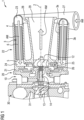
- the exhaust gas turbocharger 1 shown here has a compressor 30 with a compressor housing 31 and a bearing assembly 10 as well as a turbine 20 with a turbine housing 21 through which an exhaust gas mass flow AM can flow, which are arranged together next to one another along a turbocharger axis 2 (from left to right in the illustration).
- a compressor wheel 13 is arranged in the compressor housing 31 and a turbine wheel 12 is arranged in the turbine housing 21.
- the compressor wheel 13 and the turbine wheel 12 are arranged in a rotationally fixed manner on the opposite ends of a rotor shaft 14, together with which they form the turbocharger rotor, which is rotatably mounted with the rotor shaft 14 in the bearing assembly 10 about the turbocharger axis 2, which simultaneously represents the rotor axis of rotation and specifies the axial direction of the exhaust gas turbocharger 1.
- the turbine housing 21 has an exhaust gas supply nozzle 27, an exhaust gas discharge nozzle 28 which extends axially in the direction of the turbocharger axis 2, and an exhaust gas ring channel 22 which surrounds the turbine wheel 12 and the exhaust gas discharge nozzle 28 in relation to the turbocharger axis 2.
- the exhaust gas ring channel 22 extends in the axial direction over the exhaust gas discharge nozzle 28 and encloses it over its outer circumference.
- a hollow body-shaped catalyst substrate block 3 which is designed here as a hollow cylinder and can also be referred to as a ring catalyst, is integrated in the exhaust gas ring channel 22 in the turbine housing 21 in such a way that it fills the exhaust gas ring channel 22 all around its circumference and, together with the exhaust gas ring channel 22, surrounds the exhaust gas discharge nozzle 28.
- a possible form of a hollow body-shaped catalyst substrate block 3 is shown, namely a catalyst substrate block 3 designed as a straight hollow cylinder.
- FIG. 3 Another possible form of a hollow body-shaped catalyst substrate block 3 is shown, namely a catalyst substrate block 3 designed as a hollow truncated cone.
- an inlet ring channel 23 is formed in the exhaust gas ring channel 22, upstream of the catalyst substrate block 3, to which the exhaust gas feed pipe 27 is connected for introducing the exhaust gas mass flow AM.
- the exhaust gas mass flow AM is introduced into the exhaust gas ring channel 22 from a tangential direction via the inlet ring channel 23 and introduced into the catalyst substrate block distributed over the circumference of the inlet side of the catalyst substrate block.
- the inlet ring channel 23 can be designed, for example, as a spiral channel with a cross-section tapering in the flow direction of the exhaust gas mass flow AM, as in the Fig.1 This corresponds approximately to the geometry of an exhaust volute commonly used in turbine housings, by means of which the exhaust gas is guided in a spiral path to the catalyst inlet side 4. This advantageously enables a uniform distribution of the exhaust gas mass flow AM over the circumference of the catalyst inlet side 4 and a uniform flow through the catalyst substrate block.
- an inlet ring channel 24 is formed in the exhaust gas ring channel 22 downstream of the catalyst substrate block 3 for transferring the exhaust gas mass flow AM to the turbine wheel 12.
- the flow direction and the flow path of the exhaust gas mass flow AM through the turbine housing 21 and the catalyst substrate block 3 is marked by solid arrows and runs in the order of mention through the exhaust gas feed nozzle 27 into the inlet ring channel 23 and further through the catalyst substrate block 3 into the inlet ring channel 24 and from here through the exhaust ring gap 25 onto the turbine wheel 12 and further through the flow channel 29 of the exhaust gas discharge nozzle 28, for example into an exhaust system of a motor vehicle, for example a hybrid vehicle 50, as in Fig. 4 shown.
- the cleaned exhaust gas mass flow AM collects in the inlet ring channel 24 and then passes through the circumferential exhaust ring gap 25, which represents a cross-sectional constriction in a predominantly radial direction towards the turbine wheel 12, and flows from there onto the turbine wheel 12 and drives it.
- the exhaust gas is discharged in an axial direction via the exhaust gas discharge nozzle 28, which has a flow channel 29, which is designed, for example, as an outlet diffuser with a cross-section that widens conically in the flow direction.
- a connecting flange at the end of the exhaust gas discharge nozzle 28 is used for fastening to the exhaust system of the associated internal combustion engine.
- the exhaust gas turbocharger 1 as also exemplified in Fig. 1 shown, a catalyst substrate block 3 with a catalyst inlet side 4 located upstream in the exhaust gas mass flow AM and a catalyst outlet side 5 located downstream, wherein continuous flow channels 6 are provided in the catalyst substrate block 3 between the catalyst inlet side 4 and the catalyst outlet side 5, the course of which has an axial component with respect to the turbocharger axis 2 and a component in the circumferential direction of the hollow body-shaped catalyst substrate block 3.
- the flow channels 6 on the catalyst inlet side 4 are inclined in the circumferential direction against the flow direction of the exhaust gas mass flow AM, i.e. against the spiral course of the inlet ring channel 23, whereby the required deflection and associated flow losses of the exhaust gas mass flow upon entry into the catalyst substrate block 3 are reduced. While maintaining this inclination, the flow channels 6 run spirally through the catalyst substrate block 3 and give the exhaust gas mass flow AM on the catalyst outlet side 5 a flow direction which has a more or less large directional component in the circumferential direction of the inlet ring channel 24, into the exhaust gas ring gap 25 and onto the turbine wheel 12.
- This arrangement of the flow channels 6 advantageously reduces the flow losses of the exhaust gas mass flow and increases the power output of the turbine wheel 12, and also increases the length of the flow path through the catalyst substrate block 3, so that a high conversion rate of the pollutants in the exhaust gas mass flow AM is ensured.
- the structure of the catalyst substrate block 3 is used to optimize the flow and the power output of the turbine as well as the conversion rate of the pollutants.
- the hollow body-shaped catalyst substrate block 3 itself, as in Fig. 1 shown, have an inner tube 3a and an outer tube 3b which surrounds the catalyst substrate block 3 on its outside, which are designed, for example, as straight cylindrical tubes or as conical tubes, depending on the design of the catalyst substrate block.
- the inner tube 3a delimits the catalyst substrate block 3 towards its inner cavity and the outer tube surrounds the catalyst substrate block 3 on its outside.
- the inner tube 3a and outer tube 3b can be mechanically firmly connected to the catalyst substrate block 3 and advantageously serve both as mechanical protection and to stabilize the catalyst substrate block 3.
- Turbine wheel 12 has an exhaust gas ring gap 25 in which a variable flow guide device 26 is arranged.
- a flow guide device 26 of a turbine is also known as a "variable turbine geometry" (VTG) and is used to control the exhaust gas mass flow AM in the direction of the turbine wheel 12 and to change the passage cross section of the exhaust gas ring gap 25 in order to advantageously adapt the performance of the turbocharger in transient operating ranges of the internal combustion engine.
- VVG variable turbine geometry
- a further embodiment of the exhaust gas turbocharger according to the invention is characterized in that the exhaust gas discharge nozzle 28 of the turbine housing 21, as also in Fig.1 shown, is designed as an outlet diffuser with a flow channel 29 that widens in the flow direction of the exhaust gas mass flow AM.
- the exhaust ring channel 22 of the turbine housing and thus the catalyst substrate block integrated therein comprise the exhaust gas discharge nozzle and thus the outlet diffuser.
- the exhaust gas mass flow relaxes in the outlet diffuser and the exhaust gas back pressure acting on the turbine wheel outlet is advantageously reduced.
- the integration of the catalyst substrate block 3 according to the invention, in particular in the form of a ring catalyst, into the turbine housing 21 of the exhaust gas turbocharger 1 brings with it a number of advantages. These include, above all, the close proximity of the catalyst to the exhaust valves of the engine, so that the catalyst responds more quickly and improved cold start and restart emissions are achieved. Furthermore, compared to conventional catalysts, a higher pressure is achieved within the catalyst substrate block 3 and a good homogeneous temperature distribution is achieved within the catalyst substrate block 3, which leads to a high conversion rate for the pollutants of the exhaust gas mass flow. Furthermore, a reduced thermal load on the turbine of the exhaust gas turbocharger is achieved. In addition, a simple and cost-reduced design is achieved.
- FIG. 4 A hybrid vehicle 50 according to the invention is symbolically shown. This has an internal combustion engine 51 and an electric motor 52 and is characterized in that the internal combustion engine 51 has an inventive Exhaust gas turbocharger 1 according to one of the previously described embodiments.
- An exhaust system 53 of the hybrid vehicle 50 is connected to the exhaust gas turbocharger 1 for discharging the exhaust gas mass flow AM cleaned of pollutants.
- Such hybrid vehicles use a combination of a conventional internal combustion engine, in particular an internal combustion engine, and an electric motor.
- the electric drive is responsible for low loads and short distances, while the internal combustion engine is mainly used for higher loads and long distances or operates as a so-called “range extender” to charge the battery.
- range extender to charge the battery.
- inventive solution of the catalyst arrangement upstream of the exhaust gas turbocharger in such hybrid vehicles in order to achieve particularly good results in terms of the corresponding emissions.
- inventive solution is therefore particularly advantageous for such hybrid vehicles, since different requirements are placed on hybrid vehicles compared to vehicles with combustion engines.
- the inventive solution can therefore be implemented particularly well here.
Landscapes
- Engineering & Computer Science (AREA)
- Chemical & Material Sciences (AREA)
- Chemical Kinetics & Catalysis (AREA)
- Mechanical Engineering (AREA)
- General Engineering & Computer Science (AREA)
- Combustion & Propulsion (AREA)
- Health & Medical Sciences (AREA)
- Toxicology (AREA)
- Exhaust Gas After Treatment (AREA)
- Supercharger (AREA)
Description
- Die vorliegende Erfindung betrifft einen Abgasturbolader für eine Brennkraftmaschine mit einem Verdichter und einer Turbine, wobei die Turbine ein Turbinengehäuse mit einem Abgaszuführstutzen, einem Abgasabführstutzen, einem Abgasringkanal und ein im Turbinengehäuse angeordnetes Turbinenrad aufweist.
- Katalysatoren werden in einer Abgasanlage möglichst nah am Motor eingebaut, damit sie rasch ihre Betriebstemperatur erreichen und auch bei niedrigen Betriebstemperaturen (wie beispielsweise im Stadtverkehr) ihre Wirkung zeigen. Maßgeblich ist hier die Light-off-Temperatur des Katalysators, d.h. die Temperatur, bei der der Katalysator anfängt, Schadstoffe abzubauen.
- Generell trifft dies auch auf Fahrzeuge zu, die mit einer durch einen Abgasturbolader aufgeladenen Brennkraftmaschine ausgestattet sind. Um ein rasches Anspringen des Katalysators und eine besonders gute katalytische Umwandlungsrate zu erreichen, wäre es hier von Vorteil, den Katalysator in Bezug auf den Abgasmassenstrom stromaufwärts der Turbine des Abgasturboladers, so nah wie möglich am Motorauslass anzuordnen. Dies trifft insbesondere zu, bei einem Einsatz der Brennkraftmaschine im Verbund mit einem elektromotorischen Antrieb, zum Beispiel in einem sogenannten Hybridfahrzeug. Hier kommt es durch die häufigen Stillstandsintervalle der Brennkraftmaschine immer wieder zur Abkühlung des Katalysators und somit zu einem vergrößerten Anteil von Betriebsphasen unterhalb der Anspringtemperatur des Katalysators und so zu einem erhöhten, inakzeptablen Schadstoffausstoß. Insbesondere also in diesem Zusammenhang ist eine Verkürzung der Aufheizzeit des Katalysators durch möglichst motornahe Anordnung, in Bezug auf den Strömungsweg des Abgasmassenstroms, wünschenswert.
- Aufgrund des zusätzlichen Volumens und der Wärmekapazität hat jedoch ein stromaufwärts des Abgasturboladers angeordneter Katalysator negative Auswirkungen auf das Leistungsverhalten der Brennkraftmaschine insbesondere in transienten Lastwechselsituationen. Darüber hinaus führt ein stromaufwärts der Turbine des Abgasturboladers angeordneter Katalysator, der in Bezug auf das Kaltstartverhalten und die Emissionen vorteilhaft wäre, zu Druckverlusten und thermischen Verlusten, die eine Verschlechterung des Ansprechverhaltens in transienten Betriebsbereichen und des Verhaltens im unteren Drehmoment- bzw. Drehzahlbereich zur Folge haben. Um Auswirkungen auf das Betriebsverhalten zu verhindern, hat man daher bei herkömmlichen Kraftfahrzeugen eine Anordnung eines Katalysators stromaufwärts eines Turboladers vermieden und diesen daher stromabwärts des Turboladers vorgesehen. Soweit bekannt, sind bislang einem Turbolader vorgeschaltete Katalysatoren, d.h. stromaufwärts der Turbine angeordnete Katalysatoren, nur in stationären Anwendungsfällen eingesetzt worden. Bei Kraftfahrzeugen mit Brennkraftmaschinen bzw. Verbrennungsmotoren ist der Katalysator bislang in der Regel stromabwärts des Turboladers angeordnet worden, d.h. man hat negative Auswirkungen auf das Kaltstartverhalten und die Umwandlungsraten in Kauf genommen, um nachteilige Auswirkungen auf das Betriebsverhalten zu vermeiden.
- Der vorliegenden Erfindung liegt die Aufgabe zugrunde, einen Abgasturbolader der eingangs beschriebenen Art zur Verfügung zu stellen, der besonders niedrige Emissionen einer zugehörigen Brennkraftmaschine bewirkt, sowie ein Hybridfahrzeug anzugeben, das sich durch einen besonders niedrigen Schadstoffausstoß auszeichnet.
- Diese Aufgabe wird erfindungsgemäß bei einem Abgasturbolader und einem Hybridfahrzeug der angegebenen Art dadurch gelöst, dass stromaufwärts vor dem Turbinenrad des Abgasturboladers ein Katalysatorsubstratblock in den Abgasringkanal des Turbinengehäuse des Abgasturboladers integriert ist.
- Die
DE 10 2017 201468 A1 offenbart einen Turbolader für eine Brennkraftmaschine, aufweisend ein Lagergehäuse, in dem eine Läuferwelle drehbar gelagert ist; ein Turbinenrad, welches drehfest auf der Läuferwelle angeordnet ist; ein Turbinengehäuse, welches mechanisch an dem Lagergehäuse festgelegt ist; und einen derart stromabwärts des Turbinenrads angeordneten Ringkatalysator mit einem Katalysatorgehäuse, dass ein aus dem Turbinenrad austretender Abgasmassenstrom in den Ringkatalysator einströmen kann, wobei der Ringkatalysator zusammen mit dem Turbinengehäuse eine integrale Einheit bildet, wobei das Katalysatorgehäuse mit dem Turbinengehäuse verbunden so ist, dass zumindest ein Wandabschnitt des Turbinengehäuses von dem Abgasmassenstrom von zwei Seiten umströmt wird. - Die
EP 2 818 640 A2 offenbart einen Turbolader, der ein Turbinenrad aufweist, das in einem Turbinengehäuse montiert und über eine Welle mit einem Verdichterrad verbunden ist. Das Turbinengehäuse definiert einen Abgaseinlass, der mit einer Spirale verbunden ist, die das Turbinenrad umgibt, und eine axiale Bohrung, durch die Abgas, das das Turbinenrad passiert hat, aus dem Turbinengehäuse abgeleitet wird. Das Turbinengehäuse bildet ferner einen ringförmigen Bypass-Kanal, der die Bohrung umgibt und so angeordnet ist, dass das Abgas das Turbinenrad umgehen kann. In dem Bypasskanal ist ein ringförmiges Bypassventil angeordnet. Das Bypassventil umfasst einen festen ringförmigen Ventilsitz und ein drehbares ringförmiges Ventilelement, das koaxial zum Ventilsitz angeordnet ist. In dem ringförmigen Bypasskanal ist ein Katalysator angeordnet. Der Katalysator besteht aus voneinander beabstandeten, wellenförmigen Metallrippen, die mit einem Katalysatormaterial beschichtet sind und sich in einem allgemein ringförmigen Käfig befinden. - Die
US 2013/014503 A1 offenbart einen Turbolader und Luftansaugsysteme, insbesondere ein Turboladergehäuse mit einem integrierten Verdichtereinlasskanal und einem integrierten Turbinenauslasskanal. In einer Ausführungsform wird eine Gehäuseanordnung für ein Zwangsansaugsystem eines Verbrennungsmotors bereitgestellt. Das Gehäuse umfasst ein Turbinengehäuse, das ferner einen Turbineneinlasskanal umfasst, der in Fluidverbindung mit einer Turbinenspirale steht, die so konfiguriert ist, dass sie ein Turbinenrad aufnimmt, wobei der Turbineneinlasskanal so konfiguriert ist, dass er einen Abgasstrom von einem Abgaskrümmer des Verbrennungsmotors zu dem Turbinenrad leitet. Die Gehäusebaugruppe umfasst auch einen Turbinenauslasskanal, der in das Turbinengehäuse integriert ist, wobei der Turbinenauslasskanal in Fluidverbindung mit der Turbinenspirale steht und so konfiguriert ist, dass er den Abgasstrom zu einem Katalysator leitet, der mit dem Turbinenauslasskanal verbunden ist, wobei der Turbinenauslasskanal einen kegelförmigen Kanal umfasst. Ferner umfasst die Gehäusebaugruppe ein Verdichtergehäuse, das mit einem Verdichtereinlasskanal integriert ist, der in Fluidverbindung mit einer Verdichterspirale steht, die so konfiguriert ist, dass sie ein mit dem Turbinenrad gekoppeltes Verdichterrad aufnimmt, wobei der Verdichtereinlasskanal eine Wand umfasst, die mit der Verdichterspirale geteilt wird. - Die
DE 10 2014 003390 A1 offenbart eine Antriebseinrichtung mit einer Brennkraftmaschine, mit einer an die Brennkraftmaschine angeschlossenen Abgasanlage, die eine Katalysator zur Reinigung von Abgas der Brennkraftmaschine aufweist, und mit einer als Brenner ausgebildeten Heizvorrichtung zum Beheizen des Katalysators. Dabei ist vorgesehen, dass eine Heißgasleitung des Brenners in ein Abgasturboladergehäuse eines Abgasturboladers der Brennkraftmaschine einmündet. - Im Gegensatz zum vorstehend erwähnten Stand der Technik sieht somit die erfindungsgemäße Lehre vor, einen Katalysator stromaufwärts des Turbinenrads des Abgasturboladers im Turbinengehäuse integriert anzuordnen, wie in den unabhängigen Ansprüchen beansprucht.
- Der erfindungsgemäße Abgasturbolader für eine Brennkraftmaschine weist einen Verdichter und eine von einem Abgasmassenstrom durchströmbare Turbine auf, die zusammen entlang einer Turboladerachse angeordnet sind, wobei die Turbine ein Turbinengehäuse und ein im Turbinengehäuse angeordnetes Turbinenrad aufweist. Das Turbinengehäuse weist einen Abgaszuführstutzen, einen Abgasabführstutzen, der sich axial in Richtung der Turboladerachse erstreckt, und einen das Turbinenrad und den Abgasabführstutzen in Bezug auf die Turboladerachse umgreifenden Abgasringkanal auf. Dabei ist, bezogen auf den Abgasmassenstrom, stromaufwärts vor dem Turbinenrad und stromabwärts des Abgaszuführstutzens ein hohlkörperförmiger Katalysatorsubstratblock derart im Abgasringkanal in das Turbinengehäuse integriert, dass er den Abgasringkanal über seinen Umfang umlaufend ausfüllt und zusammen mit dem Abgasringkanal den Abgasabführstutzen umgreift.
- Dadurch ist gewährleistet, dass der gesamte, stromaufwärts des Katalysatorsubstratblocks in den Abgasringkanal eingeleitete Abgasmassenstrom den Katalysatorsubstratblock durchströmen muss, bevor er auf das Turbinenrad trifft. Der Abgasringkanal sowie der Katalysatorsubstratblock erstrecken sich dabei in axialer Richtung zumindest über einen Teil des Abgasabführstutzens, wobei der Katalysatorsubstratblock den Abgasringkanal zwar über den Umfang umlaufend aber nicht notwendigerweise über dessen gesamte axiale Erstreckung ausfüllt. Die axiale Erstreckung des Katalysatorsubstratblocks kann dabei so dimensioniert werden, dass die Länge des Strömungsweges durch den Katalysatorsubstratblock, so bemessen ist, dass eine hohe Umwandlungsrate der Schadstoffe im Abgasmassenstrom gewährleistet ist.
- Die hohlkörperförmige Ausführung des Katalysatorsubstratblocks umfasst dabei beispielsweise die Form eines geraden Hohlzylinders aber auch beispielsweise eine konisch verlaufende Hohlzylinderform, mit anderen Worten einen Hohlkegelstumpf, oder andere Hohlkörperformen, die geeignet sind zum Einbau in einen Abgasringkanal eines Turbinengehäuses.
- Das erfindungsgemäße Hybridfahrzeug weist eine Brennkraftmaschine und Elektromotor auf und ist dadurch gekennzeichnet, dass die Brennkraftmaschine einen erfindungsgemäßen Abgasturbolader, wie vorausgehend und nachfolgend beschrieben aufweist.
- Die erfindungsgemäße Ausgestaltung von Abgasturbolader und Hybridfahrzeug bringt eine Reihe von Vorteilen mit sich. Der Katalysator ist in das Turbinengehäuse integriert, so dass sich eine entsprechende Platzersparnis erreichen lässt. Ferner kann das volle katalytische Wandlervolumen stromaufwärts der Turbine des Abgasturboladers angeordnet sein, d.h. auf einen zweiten Katalysator stromabwärts des Abgasturboladers kann verzichtet werden. Auch kann eine spezielle Ausbildung des Turbinengehäuses für die Anströmung des Turbinenrades entfallen, da eine derartige Ausgestaltung auf den Katalysator übertragen werden kann, der für eine entsprechende Anströmung der Turbine sorgt. Die erfindungsgemäße Anordnung des Katalysators, integriert in das Turbinengehäuse ermöglicht die unmittelbare Anbindung des Katalysators zusammen mit dem Abgasturbolader and den Abgasauslasskrümmer der Brennkraftmaschine und ermöglicht so eine Minimierung der Strömungsweglänge zwischen Brennkraftmaschine, Katalysator und Turbolader sowie die Begrenzung der Energieverluste auf dem Strömungsweg auf ein Minimum. Dadurch wird sowohl eine schnelle Aufheizung des Katalysators auf seine Anspringtemperatur als auch ein verbessertes Ansprechverhalten des Abgasturboladers bei hoher Leistungsausbeute ermöglicht.
- Bei der vorgenannten Ausführung des Abgasturboladers kann der Katalysatorsubstratblock in Form eines sogenannten Ringkatalysators ausgebildet sein, der die Form eines Hohlzylinders oder Hohlkelgelstumpfs aufweist, der in den Abgasringkanal eingefügt ist. Dies steht im Gegensatz zu herkömmlichen massiven zylindrisch oder konisch ausgebildeten Katalysatorsubstratblöcken. Die Ringform bzw. Hohlzylinderform oder Hohlkegelstumpfform hat hier besondere Vorteile, da der Katalysatorsubstratblock hierdurch vollständig in den das Turbinenrad und den Abgasabführstutzen umgreifenden Abgasringkanal des Turbinengehäuses integriert werden kann. Dies ermöglicht einen besonders kompakten Aufbau der Kombination aus Abgasturbolader und Katalysator.
- Die erfindungsgemäße Ausführungsform hat ferner den Vorteil, dass der Katalysatoreinlass sehr nahe an dem Auslass der Brennkraftmaschine und der Katalysatorauslass sehr nahe am Turbinenrad angeordnet ist. Dies ist insbesondere dann auf kompakte Weise realisierbar, wenn der Katalysatorsubstratblock als Ringkatalysator ausgebildet ist.
- Die Erfindung sowie vorteilhafte Ausführungsformen der Erfindung werden nachfolgend anhand der Figuren der Zeichnung im Einzelnen dargestellt und erläutert. Es zeigen:
- Fig. 1
- eine schematisiert vereinfachte Darstellung einer Ausführung eines erfindungsgemäßen Abgasturboladers mit in das Turbinengehäuse integriertem Katalysatorsubstratblock, im Halbschnitt;
- Fig. 2 und 3
- zwei unterschiedliche Ausführungen eines Katalysatorsubstratblocks in vereinfachter Darstellung;
- Fig. 4
- eine stark vereinfachte Darstellung eines erfindungsgemäßen Hybridfahrzeugs mit Brennkraftmaschine, Elektromotor und einen erfindungsgemäßen Abgasturbolader.
- Der hier dargestellte Abgasturbolader 1 weist einen Verdichter 30 mit einem Verdichtergehäuse 31 und eine Lagerbaugruppe 10 sowie eine von einem Abgasmassenstrom AM durchströmbare Turbine 20 mit einem Turbinengehäuse 21 auf, die zusammen entlang einer Turboladerachse 2 nebeneinander (in der Darstellung von links nach rechts), angeordnet sind.
- In dem Verdichtergehäuse 31 ist ein Verdichterrad 13 angeordnet und in dem Turbinengehäuse 21 ist ein Turbinenrad 12 angeordnet. Das Verdichterrad 13 und das Turbinenrad 12 sind auf den sich gegenüberliegenden Enden einer Rotorwelle 14 drehfest angeordnet, bilden zusammen mit dieser den Turboladerrotor, der mit der Rotorwelle 14 in der Lagerbaugruppe 10 um die Turboladerachse 2, die gleichzeitig die Rotordrehachse darstellt und die axiale Richtung des Abgasturboladers 1 vorgibt, drehbar gelagert.
- Das Turbinengehäuse 21 weist einen Abgaszuführstutzen 27, einen Abgasabführstutzen 28, der sich axial in Richtung der Turboladerachse 2 erstreckt, und einen das Turbinenrad 12 und den Abgasabführstutzen 28 in Bezug auf die Turboladerachse 2 umgreifenden Abgasringkanal 22 auf. Der Abgasringkanal 22 erstreckt sich in axialer Richtung über den Abgasabführstutzen 28 und umschließt diesen über seinen Außenumfang.
- Bezogen auf den Abgasmassenstrom AM, der in
Fig. 1 durch massive Pfeile dargestellt ist, stromaufwärts vor dem Turbinenrad 12 und stromabwärts des Abgaszuführstutzens 27 ist ein hier als Hohlzylinder ausgebildeter, hohlkörperförmiger Katalysatorsubstratblock 3, der auch als Ringkatalysator bezeichnet werden kann, derart im Abgasringkanal 22 in das Turbinengehäuse 21 integriert, dass er den Abgasringkanal 22 über seinen Umfang umlaufend ausfüllt und zusammen mit dem Abgasringkanal 22 den Abgasabführstutzen 28 umgreift. - In
Fig. 2 ist eine mögliche Form eines hohlkörperförmigen Katalysatorsubstratblocks 3, nämlich ein als gerader Hohlzylinder ausgebildeter Katalysatorsubstratblock 3 gezeigt. - In
Fig. 3 ist eine weitere mögliche Form eines hohlkörperförmigen Katalysatorsubstratblocks 3, nämlich ein als Hohlkegelstumpf ausgebildeter Katalysatorsubstratblock 3 gezeigt. - Gemäß einer Ausführung des Abgasturboladers 1 ist im Abgasringkanal 22, stromaufwärts des Katalysatorsubstratblocks 3 ein Einlassringkanal 23 ausgebildet, an den der Abgaszuführstutzen 27 zur Einleitung des Abgasmassenstroms AM angeschlossen ist. Über den Einlassringkanal 23 wird bei dieser Ausführung der Abgasmassenstrom AM in den Abgasringkanal 22 aus tangentialer Richtung eingeleitet und über den Umfang der Einlassseite des Katalysatorsubstratblocks verteilt in den Katalysatorsubstratblock eingeleitet. Der Einlassringkanal 23 kann beispielsweise als Spiralkanal mit einem sich in Strömungsrichtung des Abgasmassenstroms AM verjüngenden Querschnitt ausgebildet sein, wie in der
Fig.1 dargestellt. Dies entspricht in etwa der Geometrie einer in Turbinengehäusen gebräuchlichen Abgasvolute, mittels der das Abgas in einer spiralförmigen Bahn auf die Katalysatoreinlassseite 4 geführt wird. Dies ermöglicht vorteilhaft eine gleichmäßige Verteilung des Abgasmassenstromes AM über den Umfang der Katalysatoreinlassseite 4 und eine gleichmäßige Durchströmung des Katalysatorsubstratblocks. - Weiterhin ist bei dieser Ausführung im Abgasringkanal 22 stromabwärts des Katalysatorsubstratblocks 3 ein Einleitringkanal 24 ausgebildet, zur Überleitung des Abgasmassenstroms AM auf das Turbinenrad 12. Dies ermöglicht vorteilhaft eine gleichmäßige Verteilung des Abgasmassenstromes AM über den Umfang des Turbinenrads 12 sowie eine über den Umfang verteilte Einleitung des Abgasmassenstromes AM in den Abgasringspalt 25 zur Überleitung auf das Turbinenrad 12.
- Die Strömungsrichtung und der Strömungsweg des Abgasmassenstromes AM durch das Turbinengehäuse 21 und den Katalysatorsubstratblock 3 ist durch massive Pfeile gekennzeichnet und verläuft in der Reihenfolge der Nennung durch den Abgaszuführstutzen 27 in den Einlassringkanal 23 und weiter durch den Katalysatorsubstratblock 3 in den Einleitringkanal 24 und von hier durch den Abgasringspalt 25 auf das Turbinenrad 12 und weiter durch den Strömungskanal 29 des Abgasabführstutzens 28 zum Beispiel in eine Abgasanlage eines Kraftfahrzeugs, beispielsweise eines Hybridfahrzeugs 50, wie in
Fig. 4 dargestellt. - Nach dem Verlassen des Katalysatorsubstratblocks 3 auf dessen Katalysatorauslassseite 5 sammelt sich der gereinigte Abgasmassenstrom AM im Einleitringkanal 24 und passiert anschließend den umlaufenden Abgasringspalt 25, der eine Querschnittsverengung in überwiegend radialer Richtung auf das Turbinenrad 12 zu darstellt, und strömt von dort auf das Turbinenrad 12 und treibt dieses an. Vom Turbinenrad 12 wird das Abgas über den Abgasabführstutzen 28, der einen Strömungskanal 29 aufweist, der beispielsweise als Auslassdiffusor mit einem sich in Strömungsrichtung konisch erweiternden Querschnitt ausgebildet ist, in axialer Richtung abgeführt. Ein Verbindungsflansch am Ende des Abgasabführstutzen 28 dient zur Befestigung am Abgassystem der zugehörigen Brennkraftmaschine.
- Gemäß einer weiteren Ausführung weist der Abtgasturbolader 1, wie ebenfalls beispielhaft in
Fig. 1 dargestellt, einen Katalysatorsubstratblock 3 auf mit einer im Abgasmassenstrom AM stromaufwärts liegenden Katalysatoreinlassseite 4 und einer stromabwärts liegenden Katalysatorauslassseite 5, wobei zwischen der Katalysatoreinlassseite 4 und der Katalysatorauslassseite 5 verlaufende durchgehende Strömungskanäle 6 im Katalysatorsubstratblock 3 vorgesehen sind, deren Verlauf mit Bezug auf die Turboladerachse 2 eine axiale Komponente und eine Komponente in Umfangsrichtung des hohlkörperförmigen Katalysatorsubstratblocks 3 aufweist. Daraus ergibt sich ein mehr oder weniger spiralförmiger Verlauf der Strömungskanäle 6, sowie eine schräg zur Katalysatoreinlassseite 4 verlaufende Eintrittsrichtung und eine schräg zur Katalysatorauslassseite 5 verlaufende Austrittsrichtung für den Abgasmassenstrom. - Vorzugsweise sind die Strömungskanäle 6 auf der Katalysatoreinlassseite 4 in Umfangsrichtung entgegen der Strömungsrichtung des Abgasmassenstroms AM, also entgegen des Spiralverlaufs des Einlassringkanals 23 geneigt, wodurch die erforderliche Umlenkung und damit verbundene Strömungsverluste des Abgasmassenstroms beim Eintritt in den Katalysatorsubstratblock 3 reduziert werden. Unter Beibehaltung dieser Neigung verlaufen die Strömungskanäle 6 spiralförmig durch den Katalysatorsubstratblock 3 und verleihen dem Abgasmassenstrom AM auf der Katalysatorauslassseite 5 eine Strömungsrichtung, die eine mehr oder weniger große Richtungskomponente in Umfangsrichtung des Einleitringkanals 24, in den Abgasringspalt 25 hinein und auf das Turbinenrad 12. Durch diese Anordnung der Strömungskanäle 6 werden zum einen die Strömungsverluste des Abgasmassenstroms vorteilhaft reduziert und die Leistungsausbeute des Turbinenrads 12 erhöht und zum anderen wird die Länge des Strömungsweges durch den Katalysatorsubstratblock 3, dadurch vergrößert, so dass eine hohe Umwandlungsrate der Schadstoffe im Abgasmassenstrom AM gewährleistet ist. Mit anderen Worten wird bei dieser Ausführungsform die Struktur des Katalysatorsubstratblocks 3 benutzt, um die Anströmung und die Leistungsausbeute der Turbine sowie die Umwandlungsrate der Schadstoffe zu optimieren.
- Bei einer weiteren Ausführung des Abgasturboladers 1 kann der hohlkörperförmige Katalysatorsubstratblock 3 selbst, wie auch in
Fig. 1 dargestellt, ein Innenrohr 3a und ein den Katalysatorsubstratblock 3 auf seiner Außenseite umfassendes Außenrohr 3b aufweisen, die beispielsweise als gerade verlaufende Zylinderrohre oder als konisch verlaufende Rohre ausgebildet sind, je nach Ausführung des Katalysatorsubstratblocks. Das Innenrohr 3a begrenzt dabei den Katalysatorsubstratblock 3 zu seinem Innenhohlraum hin und das Außenrohr umfasst den Katalysatorsubstratblock 3 auf seiner Außenseite. Innenrohr 3a und Außenrohr 3b können mechanisch fest mit dem Katalysatorsubstratblock 3 verbunden sein und dienen vorteilhaft sowohl als mechanischer Schutz als auch zur Stabilisierung des Katalysatorsubstratblocks 3. - Bei einer weiteren Ausführungsform des Abgasturboladers 1 ist stromabwärts des Katalysatorsubstratblocks 3 im Übergang zwischen Abgasringkanal 22 und dem
- Turbinenrad 12 eine Abgasringspalt 25 ausgebildet, in dem ein variabler Strömungsleitapparat 26 angeordnet ist. Ein solcher Strömungsleitapparat 26 einer Turbine ist auch als "Variable Turbinengeometrie" (VTG) bekannt und dient zur Steuerung des Abgasmassenstroms AM in Richtung auf das Turbinenrad 12 hin sowie zur Veränderung des Durchgangsquerschnitts des Abgasringspalts 25 zur vorteilhaften Anpassung der Leistung des Turboladers in transienten Betriebsbereichen der Brennkraftmaschine.
- Eine weitere Ausführung des erfindungsgemäßen Abgasturboladers ist dadurch gekennzeichnet, dass der Abgasabführstutzen 28 des Turbinengehäuses 21, wie ebenfalls in
Fig.1 dargestellt, als Auslassdiffusor mit einem sich in Strömungsrichtung des Abgasmassenstroms AM erweiternden Strömungskanal 29 ausgebildet ist. Der Abgasringkanal 22 des Turbinengehäuses und somit der darin integrierte Katalysatorsubstratblock umfassen den Abgasabführstutzen und somit den Auslassdiffusor. Im Auslassdiffusor entspannt sich der Abgasmassenstrom und der auf den Turbinenradauslass wirkende Abgasgegendruck wird vorteilhaft verringert. - Wie aus
Fig. 1 ersichtlich lassen sich die Merkmale der vorgenannten einzelnen Ausführungsformen auch in Kombination mehrerer der Merkmale oder ihrer Gesamtheit in einem Abgasturbolader verwirklichen. - Die erfindungsgemäß vorgenommene Integration des Katalysatorsubstratblocks 3, insbesondere in Form eines Ringkatalysators, in das Turbinengehäuse 21 des Abgasturboladers 1 bringt eine Reihe von Vorteilen mit sich. Hierzu zählt vor allem die enge Nachbarschaft des Katalysators zu den Auslassventilen des Motors, so dass der Katalysator schneller anspricht und verbesserte Kaltstart- und Neustartemissionen erreicht werden. Des Weiteren wird, im Vergleich zu herkömmlichen Katalysatoren, ein höherer Druck innerhalb des Katalysatorsubstratblocks 3 erzielt und innerhalb des Katalysatorsubstratblocks 3 wird eine gute homogene Temperaturverteilung erreicht, die zu einer hohen Umwandlungsrate für die Schadstoffe des Abgasmassenstroms führt. Ferner wird eine reduzierte thermische Belastung der Turbine des Abgasturboladers erzielt. Darüber hinaus wird eine einfache und kostenreduzierte Bauweise erreicht.
- In
Fig. 4 ist symbolisch ein Hybridfahrzeug 50 gemäß der Erfindung dargestellt. Dieses weist eine Brennkraftmaschine 51 und einen Elektromotor 52 auf und ist dadurch gekennzeichnet, dass die Brennkraftmaschine 51 einen erfindungsgemäßen Abgasturbolader 1 gemäß einer der vorausgehend beschriebenen Ausführungen aufweist. An den Abgasturbolader 1 angeschlossen ist eine Abgasanlage 53 des Hybridfahrzeugs 50 zur Abführung des von Schadstoffen gereinigten Abgasmassenstroms AM. - Bei derartigen Hybridfahrzeugen findet eine Kombination aus einer herkömmlichen Brennkraftmaschine, insbesondere eines Verbrennungsmotors, und einem Elektromotor Verwendung. Typischerweise ist der elektrische Antrieb für niedrige Last und kurze Fahrstrecken zuständig, während der Verbrennungsmotor vorwiegend für höhere Lasten und große Strecken in Betreib genommen wird oder als sogenannter "Range Extender" zur Aufladung der Batterie operiert. Das bedeutet, dass der Betriebsbereich des Verbrennungsmotors im Vergleich zu Fahrzeugen mit reinem Verbrennungsantrieb in Hybridfahrzeugen vergleichsweise klein ist. Das bedeutet, dass das Übergangsverhalten (Transient Response) und das Drehmomentverhalten im unteren Bereich des Verbrennungsmotors für Hybridantriebe geringere Bedeutung besitzen, andererseits jedoch das Neustartvermögen und die Emissionen größere Bedeutung gewinnen.
- Da somit bei Hybridantrieben die Anforderungen in Bezug auf das Übergangsverhalten (Transient Response) und das Drehmomentverhalten im unteren Bereich für den Verbrennungsmotor geringer sind, wird vorgeschlagen, die erfindungsgemäße Lösung der Katalysatoranordnung stromauf des Abgasturboladers bei derartigen Hybridfahrzeugen einzusetzen, um in Bezug auf die entsprechenden Emissionen besonders gute Ergebnisse zu erzielen. Für solche Hybridfahrzeuge ist daher die erfindungsgemäße Lösung besonders günstig, da im Vergleich zu Fahrzeugen mit Verbrennungsmotoren an Hybridfahrzeuge andere Anforderungen gestellt werden. Hier lässt sich daher die erfindungsgemäße Lösung besonders gut verwirklichen.
-
- 1
- Abgasturbolader
- 2
- Turboladerachse
- 3
- Katalysatorsubstratblock
- 3a
- Innenrohr
- 3b
- Außenrohr
- 4
- Katalysatoreinlassseite
- 5
- Katalysatorauslassseite
- 6
- Strömungskanäle
- 10
- Lagerbaugruppe
- 12
- Turbinenrad
- 13
- Verdichterrad
- 14
- Rotorwelle
- 20
- Turbine
- 21
- Turbinengehäuse
- 22
- Abgasringkanal
- 23
- Einlassringkanal
- 24
- Einleitringkanal
- 25
- Abgasringspalt
- 26
- Strömungsleitapparat
- 27
- Abgaszuführstutzen
- 28
- Abgasabführstutzen
- 29
- Strömungskanal des Abgasabführstutzens
- 30
- Verdichter
- 31
- Verdichtergehäuse
- 50
- Hybridfahrzeug
- 51
- Brennkraftmaschine
- 52
- Elektromotor
- 53
- Abgasanlage
- AM
- Abgasmassenstrom
Claims (7)
- Abgasturbolader (1) für eine Brennkraftmaschine (51) der einen Verdichter (30) und eine von einem Abgasmassenstrom (AM) durchströmbare Turbine (20) aufweist, die zusammen entlang einer Turboladerachse (2) angeordnet sind, wobei die Turbine (20) ein Turbinengehäuse (21) und ein im Turbinengehäuse (21) angeordnetes Turbinenrad (12) aufweist, undwobei das Turbinengehäuse (21) einen Abgaszuführstutzen (27), einen Abgasabführstutzen (28), der sich axial in Richtung der Turboladerachse (2) erstreckt, und einen das Turbinenrad (12) und den Abgasabführstutzen (28) in Bezug auf die Turboladerachse (2) umgreifenden Abgasringkanal (22) aufweist, dadurch gekennzeichnet,dass bezogen auf den Abgasmassenstrom (AM) stromaufwärts vor dem Turbinenrad (12) und stromabwärts des Abgaszuführstutzens (27) ein hohlkörperförmiger Katalysatorsubstratblock (3) derart im Abgasringkanal (22) in das Turbinengehäuse (21) integriert ist, dass er den Abgasringkanal (22) über seinen Umfang umlaufend ausfüllt und zusammen mit dem Abgasringkanal (22) den Abgasabführstutzen (28) umgreift.
- Abgasturbolader (1) nach Anspruch 1, dadurch gekennzeichnet, dass im Abgasringkanal (22) stromaufwärts des Katalysatorsubstratblocks (3) ein Einlassringkanal (23) ausgebildet ist, an den der Abgaszuführstutzen (27) zur Einleitung des Abgasmassenstroms (AM) angeschlossen ist und dass im Abgasringkanal (22) stromabwärts des Katalysatorsubstratblocks (3) ein Einleitringkanal (24) ausgebildet ist, zur Überleitung des Abgasmassenstroms (AM) auf das Turbinenrad (12) .
- Abtgasturbolader (1) nach Anspruch 1 oder 2, dadurch gekennzeichnet, dass der Katalysatorsubstratblock (3) eine im Abgasmassenstrom (AM) stromaufwärts liegenden Katalysatoreinlassseite (4) und eine stromabwärts liegende Katalysatorauslassseite (5) und zwischen der Katalysatoreinlassseite (4) und der Katalysatorauslassseite (5) verlaufende durchgehende Strömungskanäle (6) aufweist, deren Verlauf mit Bezug auf die Turboladerachse (2) eine axiale Komponente und eine Komponente in Umfangsrichtung des hohlkörperförmigen Katalysatorsubstratblocks (3) aufweist.
- Abgasturbolader (1) nach einem der Ansprüche 1 bis 3, dadurch gekennzeichnet, dass der hohlkörperförmige Katalysatorsubstratblock (3) ein Innenrohr und ein den Katalysatorsubstratblock (3) auf seiner Außenseite umfassendes Außenrohr umfasst, zur Stabilisierung des Katalysatorsubstratblocks (3).
- Abgasturbolader nach einem der vorangehenden Ansprüche, dadurch gekennzeichnet, dass stromabwärts des Katalysatorsubstratblocks (3) im Übergang zwischen Abgasringkanal (22) und dem Turbinenrad (12) eine Abgasringspalt (25) ausgebildet ist, in dem ein variabler Strömungsleitapparat (26) angeordnet ist.
- Abgasturbolader nach einem der vorangehenden Ansprüche, dadurch gekennzeichnet, dass der Abgasabführstutzen (28) als Auslassdiffusor mit einem sich in Strömungsrichtung des Abgasmassenstroms (AM) erweiternden Strömungskanal (29) ausgebildet ist.
- Hybridfahrzeug (50) mit Brennkraftmaschine (51) und Elektromotor (52), dadurch gekennzeichnet, dass die Brennkraftmaschine (51) einen Abgasturbolader (1) nach einem der vorangehenden Ansprüche aufweist.
Applications Claiming Priority (2)
| Application Number | Priority Date | Filing Date | Title |
|---|---|---|---|
| DE102020215307.8A DE102020215307A1 (de) | 2020-12-03 | 2020-12-03 | Abgasturbolader mit Katalysator und einen solchen aufweisendes Hybridfahrzeug |
| PCT/EP2021/082845 WO2022117413A1 (de) | 2020-12-03 | 2021-11-24 | Abgasturbolader mit katalysator und einen solchen aufweisendes hybridfahrzeug |
Publications (2)
| Publication Number | Publication Date |
|---|---|
| EP4256178A1 EP4256178A1 (de) | 2023-10-11 |
| EP4256178B1 true EP4256178B1 (de) | 2025-01-08 |
Family
ID=78822534
Family Applications (1)
| Application Number | Title | Priority Date | Filing Date |
|---|---|---|---|
| EP21820165.5A Active EP4256178B1 (de) | 2020-12-03 | 2021-11-24 | Abgasturbolader mit katalysator und einen solchen aufweisendes hybridfahrzeug |
Country Status (5)
| Country | Link |
|---|---|
| US (1) | US11959413B2 (de) |
| EP (1) | EP4256178B1 (de) |
| CN (1) | CN116547442B (de) |
| DE (1) | DE102020215307A1 (de) |
| WO (1) | WO2022117413A1 (de) |
Families Citing this family (1)
| Publication number | Priority date | Publication date | Assignee | Title |
|---|---|---|---|---|
| DE102021205972A1 (de) * | 2021-06-11 | 2022-12-15 | Fraunhofer-Gesellschaft zur Förderung der angewandten Forschung eingetragener Verein | Turbolader |
Family Cites Families (15)
| Publication number | Priority date | Publication date | Assignee | Title |
|---|---|---|---|---|
| DE2348866A1 (de) | 1973-09-28 | 1975-04-10 | Eberspaecher J | Verfahren zur reinigung der abgase von mit fluessigem brennstoff betriebenen motoren und einrichtung zur durchfuehrung des verfahrens |
| US4122673A (en) * | 1973-09-28 | 1978-10-31 | J. Eberspacher | Internal combustion engine with afterburning and catalytic reaction in a supercharger turbine casing |
| DE4335153C2 (de) | 1993-10-15 | 1995-09-21 | Porsche Ag | Abgasanlage für eine Brennkraftmaschine mit einem Abgas-Turbolader |
| FR2891011A1 (fr) | 2005-09-21 | 2007-03-23 | Melchior Jean F | Dispositif de suralimentation pour moteur a combustion interne, et vehicule automobile equipe d'un tel dispositif |
| WO2009118471A1 (fr) * | 2008-02-29 | 2009-10-01 | Melchior Jean-Frederic | Moteur a combustion interne a suralimentation pulsee |
| DE102008034215A1 (de) | 2008-07-23 | 2010-01-28 | Bayerische Motoren Werke Aktiengesellschaft | Brennkraftmaschine mit einem Abgasturbolader |
| DE102010005831A1 (de) * | 2010-01-27 | 2011-07-28 | GM Global Technology Operations LLC, ( n. d. Ges. d. Staates Delaware ), Mich. | Abgasstrang für eine Brennkraftmaschine sowie Verfahren zum Betreiben einer Brennkraftmaschine |
| US20120312011A1 (en) * | 2011-06-10 | 2012-12-13 | GM Global Technology Operations LLC | Turbine housing and method for directing exhaust |
| US20130014503A1 (en) * | 2011-07-15 | 2013-01-17 | GM Global Technology Operations LLC | Housing assembly for forced air induction system |
| US9003781B2 (en) * | 2013-01-24 | 2015-04-14 | Ford Global Technologies, Llc | Pre-turbocharger catalyst |
| EP2818640A3 (de) * | 2013-06-26 | 2015-08-19 | Honeywell International Inc. | Turbolader mit ringförmigem drehbarem Ringumleitungsventil für die Turbine, und Katalysator, der in dem Bypasskanal des Turbinengehäuses angeordnet ist |
| DE102014003390B4 (de) * | 2014-03-07 | 2023-05-11 | Audi Ag | Antriebseinrichtung |
| US9689397B2 (en) * | 2014-06-13 | 2017-06-27 | GM Global Technology Operations LLC | Turbine outlet diffuser |
| DE102017201468A1 (de) | 2017-01-31 | 2018-08-02 | Continental Automotive Gmbh | Turbolader für eine Brennkraftmaschine |
| US10570778B2 (en) * | 2017-09-11 | 2020-02-25 | Ford Global Technologies, Llc | Coupling system for turbocharger and emission control device |
-
2020
- 2020-12-03 DE DE102020215307.8A patent/DE102020215307A1/de active Pending
-
2021
- 2021-11-24 US US18/265,031 patent/US11959413B2/en active Active
- 2021-11-24 WO PCT/EP2021/082845 patent/WO2022117413A1/de not_active Ceased
- 2021-11-24 CN CN202180081124.5A patent/CN116547442B/zh active Active
- 2021-11-24 EP EP21820165.5A patent/EP4256178B1/de active Active
Also Published As
| Publication number | Publication date |
|---|---|
| CN116547442A (zh) | 2023-08-04 |
| WO2022117413A1 (de) | 2022-06-09 |
| DE102020215307A1 (de) | 2022-06-09 |
| US11959413B2 (en) | 2024-04-16 |
| CN116547442B (zh) | 2026-03-20 |
| EP4256178A1 (de) | 2023-10-11 |
| US20240026811A1 (en) | 2024-01-25 |
Similar Documents
| Publication | Publication Date | Title |
|---|---|---|
| EP1460237B1 (de) | Abgasturbinengehäuse | |
| EP2329555B1 (de) | Luftversorgungseinrichtung für einen brennstoffzellenstapel, brennstoffzellensystem und verfahren zum betreiben einer luftversorgungseinrichtung | |
| DE19924228A1 (de) | Mehrflutiger, regelbarer Abgasturbolader | |
| WO2010040437A2 (de) | Abgasturbolader für eine brennkraftmaschine | |
| WO2010003537A2 (de) | Turbinengehäuse für einen abgasturbolader einer brennkraftmaschine | |
| EP2143924A1 (de) | Aufgeladene Brennkraftmaschine | |
| DE3631130A1 (de) | Abgasgetriebener zweikanal-turbolader | |
| WO2018141608A1 (de) | Abgasturbolader mit ringkatalysator für eine brennkraftmaschine | |
| EP1222400A1 (de) | Verfahren und vorrichtung zur indirekten kühlung der strömung in zwischen rotoren und statoren von turbomaschinen ausgebildeten radialspalten | |
| EP4256178B1 (de) | Abgasturbolader mit katalysator und einen solchen aufweisendes hybridfahrzeug | |
| EP2859190B1 (de) | Turbinengehäuse für einen abgasturbolader | |
| DE3432683A1 (de) | Stroemungsmaschine | |
| EP2112332B1 (de) | Trägerring einer Leitvorrichtung mit Sperrluftkanal | |
| EP2143925A1 (de) | Anordnung mit Zylinderkopf und Turbine | |
| AT504446B1 (de) | Abgasturbolader | |
| EP2574795B1 (de) | Abgasturbolader für eine Verbrennungskraftmaschine | |
| DE19654026A1 (de) | Abgasanlage für eine aufgeladene Brennkraftmaschine | |
| EP2788591A1 (de) | Turbine für einen abgasturbolader | |
| DE102012023408B4 (de) | Turbine für einen Abgasturbolader und Verbrennungsmaschine, insbesondere für Kraftwagen | |
| EP1586842A1 (de) | Verfahren zum Kühlen von Abgas eines Verbrennungsmotors eines Fahrzeugs sowie Wärmeübertrager | |
| DE2154726A1 (de) | Radial beaufschlagter abgasturbolader | |
| DE10337336B4 (de) | Abgasanlage für eine Brennkraftmaschine | |
| DE102007017844B4 (de) | Abgasturbolader, Brennkraftmaschine mit diesem Abgasturbolader und Verfahren zum Regeln des Ladedrucks des Abgasturboladers | |
| WO2009127332A1 (de) | Vorrichtung zur luftversorgung | |
| WO2018188777A2 (de) | Lagerabschnitt für einen abgasturbolader und abgasturbolader |
Legal Events
| Date | Code | Title | Description |
|---|---|---|---|
| STAA | Information on the status of an ep patent application or granted ep patent |
Free format text: STATUS: UNKNOWN |
|
| STAA | Information on the status of an ep patent application or granted ep patent |
Free format text: STATUS: THE INTERNATIONAL PUBLICATION HAS BEEN MADE |
|
| PUAI | Public reference made under article 153(3) epc to a published international application that has entered the european phase |
Free format text: ORIGINAL CODE: 0009012 |
|
| STAA | Information on the status of an ep patent application or granted ep patent |
Free format text: STATUS: REQUEST FOR EXAMINATION WAS MADE |
|
| 17P | Request for examination filed |
Effective date: 20230703 |
|
| AK | Designated contracting states |
Kind code of ref document: A1 Designated state(s): AL AT BE BG CH CY CZ DE DK EE ES FI FR GB GR HR HU IE IS IT LI LT LU LV MC MK MT NL NO PL PT RO RS SE SI SK SM TR |
|
| DAV | Request for validation of the european patent (deleted) | ||
| DAX | Request for extension of the european patent (deleted) | ||
| GRAP | Despatch of communication of intention to grant a patent |
Free format text: ORIGINAL CODE: EPIDOSNIGR1 |
|
| STAA | Information on the status of an ep patent application or granted ep patent |
Free format text: STATUS: GRANT OF PATENT IS INTENDED |
|
| INTG | Intention to grant announced |
Effective date: 20240710 |
|
| P01 | Opt-out of the competence of the unified patent court (upc) registered |
Free format text: CASE NUMBER: APP_50685/2024 Effective date: 20240906 |
|
| GRAS | Grant fee paid |
Free format text: ORIGINAL CODE: EPIDOSNIGR3 |
|
| GRAA | (expected) grant |
Free format text: ORIGINAL CODE: 0009210 |
|
| STAA | Information on the status of an ep patent application or granted ep patent |
Free format text: STATUS: THE PATENT HAS BEEN GRANTED |
|
| AK | Designated contracting states |
Kind code of ref document: B1 Designated state(s): AL AT BE BG CH CY CZ DE DK EE ES FI FR GB GR HR HU IE IS IT LI LT LU LV MC MK MT NL NO PL PT RO RS SE SI SK SM TR |
|
| REG | Reference to a national code |
Ref country code: GB Ref legal event code: FG4D Free format text: NOT ENGLISH |
|
| REG | Reference to a national code |
Ref country code: CH Ref legal event code: EP |
|
| REG | Reference to a national code |
Ref country code: DE Ref legal event code: R096 Ref document number: 502021006398 Country of ref document: DE |
|
| REG | Reference to a national code |
Ref country code: IE Ref legal event code: FG4D Free format text: LANGUAGE OF EP DOCUMENT: GERMAN |
|
| REG | Reference to a national code |
Ref country code: DE Ref legal event code: R081 Ref document number: 502021006398 Country of ref document: DE Owner name: SCHAEFFLER TECHNOLOGIES AG & CO. KG, DE Free format text: FORMER OWNER: VITESCO TECHNOLOGIES GMBH, 93055 REGENSBURG, DE |
|
| RAP2 | Party data changed (patent owner data changed or rights of a patent transferred) |
Owner name: SCHAEFFLER TECHNOLOGIES AG & CO. KG |
|
| REG | Reference to a national code |
Ref country code: LT Ref legal event code: MG9D |
|
| REG | Reference to a national code |
Ref country code: NL Ref legal event code: MP Effective date: 20250108 |
|
| PG25 | Lapsed in a contracting state [announced via postgrant information from national office to epo] |
Ref country code: NL Free format text: LAPSE BECAUSE OF FAILURE TO SUBMIT A TRANSLATION OF THE DESCRIPTION OR TO PAY THE FEE WITHIN THE PRESCRIBED TIME-LIMIT Effective date: 20250108 |
|
| PG25 | Lapsed in a contracting state [announced via postgrant information from national office to epo] |
Ref country code: RS Free format text: LAPSE BECAUSE OF FAILURE TO SUBMIT A TRANSLATION OF THE DESCRIPTION OR TO PAY THE FEE WITHIN THE PRESCRIBED TIME-LIMIT Effective date: 20250408 |
|
| PG25 | Lapsed in a contracting state [announced via postgrant information from national office to epo] |
Ref country code: FI Free format text: LAPSE BECAUSE OF FAILURE TO SUBMIT A TRANSLATION OF THE DESCRIPTION OR TO PAY THE FEE WITHIN THE PRESCRIBED TIME-LIMIT Effective date: 20250108 |
|
| PG25 | Lapsed in a contracting state [announced via postgrant information from national office to epo] |
Ref country code: PL Free format text: LAPSE BECAUSE OF FAILURE TO SUBMIT A TRANSLATION OF THE DESCRIPTION OR TO PAY THE FEE WITHIN THE PRESCRIBED TIME-LIMIT Effective date: 20250108 |
|
| PG25 | Lapsed in a contracting state [announced via postgrant information from national office to epo] |
Ref country code: ES Free format text: LAPSE BECAUSE OF FAILURE TO SUBMIT A TRANSLATION OF THE DESCRIPTION OR TO PAY THE FEE WITHIN THE PRESCRIBED TIME-LIMIT Effective date: 20250108 |
|
| PG25 | Lapsed in a contracting state [announced via postgrant information from national office to epo] |
Ref country code: NO Free format text: LAPSE BECAUSE OF FAILURE TO SUBMIT A TRANSLATION OF THE DESCRIPTION OR TO PAY THE FEE WITHIN THE PRESCRIBED TIME-LIMIT Effective date: 20250408 Ref country code: IS Free format text: LAPSE BECAUSE OF FAILURE TO SUBMIT A TRANSLATION OF THE DESCRIPTION OR TO PAY THE FEE WITHIN THE PRESCRIBED TIME-LIMIT Effective date: 20250508 |
|
| PG25 | Lapsed in a contracting state [announced via postgrant information from national office to epo] |
Ref country code: HR Free format text: LAPSE BECAUSE OF FAILURE TO SUBMIT A TRANSLATION OF THE DESCRIPTION OR TO PAY THE FEE WITHIN THE PRESCRIBED TIME-LIMIT Effective date: 20250108 |
|
| PG25 | Lapsed in a contracting state [announced via postgrant information from national office to epo] |
Ref country code: LV Free format text: LAPSE BECAUSE OF FAILURE TO SUBMIT A TRANSLATION OF THE DESCRIPTION OR TO PAY THE FEE WITHIN THE PRESCRIBED TIME-LIMIT Effective date: 20250108 Ref country code: PT Free format text: LAPSE BECAUSE OF FAILURE TO SUBMIT A TRANSLATION OF THE DESCRIPTION OR TO PAY THE FEE WITHIN THE PRESCRIBED TIME-LIMIT Effective date: 20250508 |
|
| PG25 | Lapsed in a contracting state [announced via postgrant information from national office to epo] |
Ref country code: GR Free format text: LAPSE BECAUSE OF FAILURE TO SUBMIT A TRANSLATION OF THE DESCRIPTION OR TO PAY THE FEE WITHIN THE PRESCRIBED TIME-LIMIT Effective date: 20250409 Ref country code: BG Free format text: LAPSE BECAUSE OF FAILURE TO SUBMIT A TRANSLATION OF THE DESCRIPTION OR TO PAY THE FEE WITHIN THE PRESCRIBED TIME-LIMIT Effective date: 20250108 |
|
| PG25 | Lapsed in a contracting state [announced via postgrant information from national office to epo] |
Ref country code: SE Free format text: LAPSE BECAUSE OF FAILURE TO SUBMIT A TRANSLATION OF THE DESCRIPTION OR TO PAY THE FEE WITHIN THE PRESCRIBED TIME-LIMIT Effective date: 20250108 |
|
| PG25 | Lapsed in a contracting state [announced via postgrant information from national office to epo] |
Ref country code: SM Free format text: LAPSE BECAUSE OF FAILURE TO SUBMIT A TRANSLATION OF THE DESCRIPTION OR TO PAY THE FEE WITHIN THE PRESCRIBED TIME-LIMIT Effective date: 20250108 |
|
| REG | Reference to a national code |
Ref country code: DE Ref legal event code: R097 Ref document number: 502021006398 Country of ref document: DE |
|
| PG25 | Lapsed in a contracting state [announced via postgrant information from national office to epo] |
Ref country code: DK Free format text: LAPSE BECAUSE OF FAILURE TO SUBMIT A TRANSLATION OF THE DESCRIPTION OR TO PAY THE FEE WITHIN THE PRESCRIBED TIME-LIMIT Effective date: 20250108 |
|
| PG25 | Lapsed in a contracting state [announced via postgrant information from national office to epo] |
Ref country code: CZ Free format text: LAPSE BECAUSE OF FAILURE TO SUBMIT A TRANSLATION OF THE DESCRIPTION OR TO PAY THE FEE WITHIN THE PRESCRIBED TIME-LIMIT Effective date: 20250108 Ref country code: EE Free format text: LAPSE BECAUSE OF FAILURE TO SUBMIT A TRANSLATION OF THE DESCRIPTION OR TO PAY THE FEE WITHIN THE PRESCRIBED TIME-LIMIT Effective date: 20250108 |
|
| PG25 | Lapsed in a contracting state [announced via postgrant information from national office to epo] |
Ref country code: RO Free format text: LAPSE BECAUSE OF FAILURE TO SUBMIT A TRANSLATION OF THE DESCRIPTION OR TO PAY THE FEE WITHIN THE PRESCRIBED TIME-LIMIT Effective date: 20250108 |
|
| PG25 | Lapsed in a contracting state [announced via postgrant information from national office to epo] |
Ref country code: SK Free format text: LAPSE BECAUSE OF FAILURE TO SUBMIT A TRANSLATION OF THE DESCRIPTION OR TO PAY THE FEE WITHIN THE PRESCRIBED TIME-LIMIT Effective date: 20250108 |
|
| PLBE | No opposition filed within time limit |
Free format text: ORIGINAL CODE: 0009261 |
|
| STAA | Information on the status of an ep patent application or granted ep patent |
Free format text: STATUS: NO OPPOSITION FILED WITHIN TIME LIMIT |
|
| 26N | No opposition filed |
Effective date: 20251009 |
|
| PGFP | Annual fee paid to national office [announced via postgrant information from national office to epo] |
Ref country code: DE Payment date: 20251130 Year of fee payment: 5 |
|
| PGFP | Annual fee paid to national office [announced via postgrant information from national office to epo] |
Ref country code: AT Payment date: 20260113 Year of fee payment: 5 |
|
| PGFP | Annual fee paid to national office [announced via postgrant information from national office to epo] |
Ref country code: FR Payment date: 20251126 Year of fee payment: 5 |
|
| PG25 | Lapsed in a contracting state [announced via postgrant information from national office to epo] |
Ref country code: IT Free format text: LAPSE BECAUSE OF FAILURE TO SUBMIT A TRANSLATION OF THE DESCRIPTION OR TO PAY THE FEE WITHIN THE PRESCRIBED TIME-LIMIT Effective date: 20250108 |