EP4256178B1 - Turbocompresseur doté d'un convertisseur catalytique, et véhicule hybride équipé d'un tel turbocompresseur - Google Patents
Turbocompresseur doté d'un convertisseur catalytique, et véhicule hybride équipé d'un tel turbocompresseur Download PDFInfo
- Publication number
- EP4256178B1 EP4256178B1 EP21820165.5A EP21820165A EP4256178B1 EP 4256178 B1 EP4256178 B1 EP 4256178B1 EP 21820165 A EP21820165 A EP 21820165A EP 4256178 B1 EP4256178 B1 EP 4256178B1
- Authority
- EP
- European Patent Office
- Prior art keywords
- exhaust gas
- turbocharger
- turbine
- substrate block
- catalyst substrate
- Prior art date
- Legal status (The legal status is an assumption and is not a legal conclusion. Google has not performed a legal analysis and makes no representation as to the accuracy of the status listed.)
- Active
Links
Images


Classifications
-
- F—MECHANICAL ENGINEERING; LIGHTING; HEATING; WEAPONS; BLASTING
- F01—MACHINES OR ENGINES IN GENERAL; ENGINE PLANTS IN GENERAL; STEAM ENGINES
- F01D—NON-POSITIVE DISPLACEMENT MACHINES OR ENGINES, e.g. STEAM TURBINES
- F01D9/00—Stators
- F01D9/02—Nozzles; Nozzle boxes; Stator blades; Guide conduits, e.g. individual nozzles
- F01D9/026—Scrolls for radial machines or engines
-
- F—MECHANICAL ENGINEERING; LIGHTING; HEATING; WEAPONS; BLASTING
- F02—COMBUSTION ENGINES; HOT-GAS OR COMBUSTION-PRODUCT ENGINE PLANTS
- F02B—INTERNAL-COMBUSTION PISTON ENGINES; COMBUSTION ENGINES IN GENERAL
- F02B37/00—Engines characterised by provision of pumps driven at least for part of the time by exhaust
- F02B37/02—Gas passages between engine outlet and pump drive, e.g. reservoirs
- F02B37/025—Multiple scrolls or multiple gas passages guiding the gas to the pump drive
-
- F—MECHANICAL ENGINEERING; LIGHTING; HEATING; WEAPONS; BLASTING
- F01—MACHINES OR ENGINES IN GENERAL; ENGINE PLANTS IN GENERAL; STEAM ENGINES
- F01D—NON-POSITIVE DISPLACEMENT MACHINES OR ENGINES, e.g. STEAM TURBINES
- F01D15/00—Adaptations of machines or engines for special use; Combinations of engines with devices driven thereby
- F01D15/02—Adaptations for driving vehicles, e.g. locomotives
-
- F—MECHANICAL ENGINEERING; LIGHTING; HEATING; WEAPONS; BLASTING
- F01—MACHINES OR ENGINES IN GENERAL; ENGINE PLANTS IN GENERAL; STEAM ENGINES
- F01N—GAS-FLOW SILENCERS OR EXHAUST APPARATUS FOR MACHINES OR ENGINES IN GENERAL; GAS-FLOW SILENCERS OR EXHAUST APPARATUS FOR INTERNAL-COMBUSTION ENGINES
- F01N3/00—Exhaust or silencing apparatus having means for purifying, rendering innocuous, or otherwise treating exhaust
- F01N3/08—Exhaust or silencing apparatus having means for purifying, rendering innocuous, or otherwise treating exhaust for rendering innocuous
- F01N3/10—Exhaust or silencing apparatus having means for purifying, rendering innocuous, or otherwise treating exhaust for rendering innocuous by thermal or catalytic conversion of noxious components of exhaust
- F01N3/24—Exhaust or silencing apparatus having means for purifying, rendering innocuous, or otherwise treating exhaust for rendering innocuous by thermal or catalytic conversion of noxious components of exhaust characterised by constructional aspects of converting apparatus
- F01N3/28—Construction of catalytic reactors
- F01N3/2882—Catalytic reactors combined or associated with other devices, e.g. exhaust silencers or other exhaust purification devices
-
- F—MECHANICAL ENGINEERING; LIGHTING; HEATING; WEAPONS; BLASTING
- F01—MACHINES OR ENGINES IN GENERAL; ENGINE PLANTS IN GENERAL; STEAM ENGINES
- F01N—GAS-FLOW SILENCERS OR EXHAUST APPARATUS FOR MACHINES OR ENGINES IN GENERAL; GAS-FLOW SILENCERS OR EXHAUST APPARATUS FOR INTERNAL-COMBUSTION ENGINES
- F01N2340/00—Dimensional characteristics of the exhaust system, e.g. length, diameter or volume of the exhaust apparatus; Spatial arrangements of exhaust apparatuses
-
- F—MECHANICAL ENGINEERING; LIGHTING; HEATING; WEAPONS; BLASTING
- F01—MACHINES OR ENGINES IN GENERAL; ENGINE PLANTS IN GENERAL; STEAM ENGINES
- F01N—GAS-FLOW SILENCERS OR EXHAUST APPARATUS FOR MACHINES OR ENGINES IN GENERAL; GAS-FLOW SILENCERS OR EXHAUST APPARATUS FOR INTERNAL-COMBUSTION ENGINES
- F01N2340/00—Dimensional characteristics of the exhaust system, e.g. length, diameter or volume of the exhaust apparatus; Spatial arrangements of exhaust apparatuses
- F01N2340/06—Arrangement of the exhaust apparatus relative to the turbine of a turbocharger
-
- F—MECHANICAL ENGINEERING; LIGHTING; HEATING; WEAPONS; BLASTING
- F05—INDEXING SCHEMES RELATING TO ENGINES OR PUMPS IN VARIOUS SUBCLASSES OF CLASSES F01-F04
- F05D—INDEXING SCHEME FOR ASPECTS RELATING TO NON-POSITIVE-DISPLACEMENT MACHINES OR ENGINES, GAS-TURBINES OR JET-PROPULSION PLANTS
- F05D2220/00—Application
- F05D2220/40—Application in turbochargers
-
- Y—GENERAL TAGGING OF NEW TECHNOLOGICAL DEVELOPMENTS; GENERAL TAGGING OF CROSS-SECTIONAL TECHNOLOGIES SPANNING OVER SEVERAL SECTIONS OF THE IPC; TECHNICAL SUBJECTS COVERED BY FORMER USPC CROSS-REFERENCE ART COLLECTIONS [XRACs] AND DIGESTS
- Y02—TECHNOLOGIES OR APPLICATIONS FOR MITIGATION OR ADAPTATION AGAINST CLIMATE CHANGE
- Y02T—CLIMATE CHANGE MITIGATION TECHNOLOGIES RELATED TO TRANSPORTATION
- Y02T10/00—Road transport of goods or passengers
- Y02T10/10—Internal combustion engine [ICE] based vehicles
- Y02T10/12—Improving ICE efficiencies
-
- Y—GENERAL TAGGING OF NEW TECHNOLOGICAL DEVELOPMENTS; GENERAL TAGGING OF CROSS-SECTIONAL TECHNOLOGIES SPANNING OVER SEVERAL SECTIONS OF THE IPC; TECHNICAL SUBJECTS COVERED BY FORMER USPC CROSS-REFERENCE ART COLLECTIONS [XRACs] AND DIGESTS
- Y02—TECHNOLOGIES OR APPLICATIONS FOR MITIGATION OR ADAPTATION AGAINST CLIMATE CHANGE
- Y02T—CLIMATE CHANGE MITIGATION TECHNOLOGIES RELATED TO TRANSPORTATION
- Y02T10/00—Road transport of goods or passengers
- Y02T10/60—Other road transportation technologies with climate change mitigation effect
- Y02T10/62—Hybrid vehicles
Definitions
- the present invention relates to an exhaust gas turbocharger for an internal combustion engine with a compressor and a turbine, wherein the turbine has a turbine housing with an exhaust gas supply nozzle, an exhaust gas discharge nozzle, an exhaust gas ring channel and a turbine wheel arranged in the turbine housing.
- Catalytic converters are installed in an exhaust system as close to the engine as possible so that they reach their operating temperature quickly and are effective even at low operating temperatures (such as in city traffic).
- the decisive factor here is the light-off temperature of the catalyst, i.e. the temperature at which the catalyst begins to break down pollutants.
- a catalyst arranged upstream of the exhaust gas turbocharger has a negative impact on the performance of the internal combustion engine, particularly in transient load change situations.
- a catalyst arranged upstream of the turbine of the exhaust gas turbocharger which would be advantageous in terms of cold start behavior and emissions, leads to pressure losses and thermal losses, which result in a deterioration in the response behavior in transient operating ranges and in the behavior in the lower torque or speed range.
- the arrangement of a catalyst upstream of a turbocharger has been avoided in conventional motor vehicles and instead it has been arranged downstream of the turbocharger.
- catalysts arranged upstream of a turbocharger ie catalysts arranged upstream of the turbine
- the catalyst has generally been arranged downstream of the turbocharger, ie negative effects on cold start behavior and conversion rates have been accepted in order to avoid adverse effects on the operating behavior.
- the present invention is based on the object of providing an exhaust gas turbocharger of the type described at the outset, which causes particularly low emissions from an associated internal combustion engine, and of specifying a hybrid vehicle which is characterized by particularly low pollutant emissions.
- the DE 10 2017 201468 A1 discloses a turbocharger for an internal combustion engine, having a bearing housing in which a rotor shaft is rotatably mounted; a turbine wheel which is arranged in a rotationally fixed manner on the rotor shaft; a turbine housing which is mechanically fixed to the bearing housing; and a ring catalyst arranged downstream of the turbine wheel with a catalyst housing such that an exhaust gas mass flow emerging from the turbine wheel can flow into the ring catalyst, wherein the ring catalyst forms an integral unit together with the turbine housing, wherein the catalyst housing is connected to the turbine housing such that at least one wall section of the turbine housing is flowed around by the exhaust gas mass flow from two sides.
- the EP 2 818 640 A2 discloses a turbocharger having a turbine wheel mounted in a turbine housing and connected to a compressor wheel via a shaft.
- the turbine housing defines an exhaust inlet connected to a volute surrounding the turbine wheel and an axial bore through which exhaust gas that has passed through the turbine wheel is discharged from the turbine housing.
- the turbine housing further defines an annular bypass channel surrounding the bore and arranged to allow exhaust gas to bypass the turbine wheel.
- An annular bypass valve is arranged in the bypass channel.
- the bypass valve includes a fixed annular valve seat and a rotatable annular valve element arranged coaxially with the valve seat.
- a catalyst is arranged in the annular bypass channel.
- the catalyst consists of spaced apart, undulating metal fins coated with a catalyst material and located in a generally annular cage.
- the US 2013/014503 A1 discloses a turbocharger and air intake systems, in particular a turbocharger housing with an integrated compressor inlet duct and an integrated turbine exhaust duct.
- a housing assembly for a forced induction system of an internal combustion engine is provided.
- the housing includes a turbine housing further comprising a turbine inlet duct in fluid communication with a turbine volute configured to receive a turbine wheel, the turbine inlet duct configured to direct an exhaust gas flow from an exhaust manifold of the internal combustion engine to the turbine wheel.
- the housing assembly also includes a turbine exhaust duct integrated into the turbine housing, the turbine exhaust duct in fluid communication with the turbine volute and configured to direct the exhaust gas flow to a catalyst connected to the turbine exhaust duct, the turbine exhaust duct comprising a cone-shaped duct.
- the housing assembly further includes a compressor housing integrated with a compressor inlet passage in fluid communication with a compressor scroll configured to receive a compressor wheel coupled to the turbine wheel, the compressor inlet passage including a wall shared with the compressor scroll.
- the DE 10 2014 003390 A1 discloses a drive device with an internal combustion engine, with a connected to the internal combustion engine Exhaust system having a catalyst for cleaning exhaust gases from the internal combustion engine, and having a heating device designed as a burner for heating the catalyst. It is provided that a hot gas line of the burner opens into an exhaust turbocharger housing of an exhaust turbocharger of the internal combustion engine.
- the teaching according to the invention thus provides for arranging a catalyst upstream of the turbine wheel of the exhaust gas turbocharger integrated in the turbine housing, as claimed in the independent claims.
- the exhaust gas turbocharger according to the invention for an internal combustion engine has a compressor and a turbine through which an exhaust gas mass flow can flow, which are arranged together along a turbocharger axis, wherein the turbine has a turbine housing and a turbine wheel arranged in the turbine housing.
- the turbine housing has an exhaust gas supply nozzle, an exhaust gas discharge nozzle which extends axially in the direction of the turbocharger axis, and an exhaust ring channel which surrounds the turbine wheel and the exhaust gas discharge nozzle in relation to the turbocharger axis.
- a hollow body-shaped catalyst substrate block is integrated into the exhaust ring channel in the turbine housing in such a way that it fills the exhaust ring channel all the way around its circumference and, together with the exhaust ring channel, surrounds the exhaust gas discharge nozzle.
- the exhaust ring channel and the catalyst substrate block extend in the axial direction over at least part of the exhaust gas discharge nozzle, with the catalyst substrate block filling the exhaust ring channel around the circumference but not necessarily over its entire axial extent.
- the axial extent of the catalyst substrate block can be dimensioned such that the length of the flow path through the catalyst substrate block is such that a high conversion rate of the pollutants in the exhaust gas mass flow is ensured.
- the hollow body-shaped design of the catalyst substrate block includes, for example, the shape of a straight hollow cylinder but also, for example, a conical hollow cylinder shape, in other words a hollow truncated cone, or other hollow body shapes that are suitable for installation in an exhaust ring channel of a turbine housing.
- the hybrid vehicle according to the invention has an internal combustion engine and electric motor and is characterized in that the internal combustion engine has an exhaust gas turbocharger according to the invention, as described above and below.
- the inventive design of the exhaust gas turbocharger and hybrid vehicle brings with it a number of advantages.
- the catalyst is integrated into the turbine housing, so that a corresponding space saving can be achieved.
- the full catalytic converter volume can be arranged upstream of the turbine of the exhaust gas turbocharger, i.e. a second catalyst downstream of the exhaust gas turbocharger can be dispensed with.
- a special design of the turbine housing for the flow to the turbine wheel can also be dispensed with, since such a design can be transferred to the catalyst, which ensures a corresponding flow to the turbine.
- the inventive arrangement of the catalyst integrated into the turbine housing, enables the catalyst to be directly connected together with the exhaust gas turbocharger to the exhaust gas outlet manifold of the internal combustion engine, thus enabling the flow path length between the internal combustion engine, catalyst and turbocharger to be minimized and the energy losses on the flow path to be limited to a minimum. This enables both rapid heating of the catalyst to its light-off temperature and improved response of the exhaust gas turbocharger with high power output.
- the catalyst substrate block can be designed in the form of a so-called ring catalyst, which has the shape of a hollow cylinder or hollow truncated cone that is inserted into the exhaust gas ring channel.
- ring catalyst which has the shape of a hollow cylinder or hollow truncated cone that is inserted into the exhaust gas ring channel.
- the ring shape or hollow cylinder shape or hollow truncated cone shape has particular advantages here, since the catalyst substrate block can thereby be completely inserted into the exhaust gas ring channel of the turbine housing that encompasses the turbine wheel and the exhaust gas discharge nozzle. This enables a particularly compact design of the combination of exhaust turbocharger and catalyst.
- the embodiment according to the invention also has the advantage that the catalyst inlet is arranged very close to the outlet of the internal combustion engine and the catalyst outlet is arranged very close to the turbine wheel. This can be implemented in a compact manner in particular if the catalyst substrate block is designed as a ring catalyst.
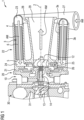
- the exhaust gas turbocharger 1 shown here has a compressor 30 with a compressor housing 31 and a bearing assembly 10 as well as a turbine 20 with a turbine housing 21 through which an exhaust gas mass flow AM can flow, which are arranged together next to one another along a turbocharger axis 2 (from left to right in the illustration).
- a compressor wheel 13 is arranged in the compressor housing 31 and a turbine wheel 12 is arranged in the turbine housing 21.
- the compressor wheel 13 and the turbine wheel 12 are arranged in a rotationally fixed manner on the opposite ends of a rotor shaft 14, together with which they form the turbocharger rotor, which is rotatably mounted with the rotor shaft 14 in the bearing assembly 10 about the turbocharger axis 2, which simultaneously represents the rotor axis of rotation and specifies the axial direction of the exhaust gas turbocharger 1.
- the turbine housing 21 has an exhaust gas supply nozzle 27, an exhaust gas discharge nozzle 28 which extends axially in the direction of the turbocharger axis 2, and an exhaust gas ring channel 22 which surrounds the turbine wheel 12 and the exhaust gas discharge nozzle 28 in relation to the turbocharger axis 2.
- the exhaust gas ring channel 22 extends in the axial direction over the exhaust gas discharge nozzle 28 and encloses it over its outer circumference.
- a hollow body-shaped catalyst substrate block 3 which is designed here as a hollow cylinder and can also be referred to as a ring catalyst, is integrated in the exhaust gas ring channel 22 in the turbine housing 21 in such a way that it fills the exhaust gas ring channel 22 all around its circumference and, together with the exhaust gas ring channel 22, surrounds the exhaust gas discharge nozzle 28.
- a possible form of a hollow body-shaped catalyst substrate block 3 is shown, namely a catalyst substrate block 3 designed as a straight hollow cylinder.
- FIG. 3 Another possible form of a hollow body-shaped catalyst substrate block 3 is shown, namely a catalyst substrate block 3 designed as a hollow truncated cone.
- an inlet ring channel 23 is formed in the exhaust gas ring channel 22, upstream of the catalyst substrate block 3, to which the exhaust gas feed pipe 27 is connected for introducing the exhaust gas mass flow AM.
- the exhaust gas mass flow AM is introduced into the exhaust gas ring channel 22 from a tangential direction via the inlet ring channel 23 and introduced into the catalyst substrate block distributed over the circumference of the inlet side of the catalyst substrate block.
- the inlet ring channel 23 can be designed, for example, as a spiral channel with a cross-section tapering in the flow direction of the exhaust gas mass flow AM, as in the Fig.1 This corresponds approximately to the geometry of an exhaust volute commonly used in turbine housings, by means of which the exhaust gas is guided in a spiral path to the catalyst inlet side 4. This advantageously enables a uniform distribution of the exhaust gas mass flow AM over the circumference of the catalyst inlet side 4 and a uniform flow through the catalyst substrate block.
- an inlet ring channel 24 is formed in the exhaust gas ring channel 22 downstream of the catalyst substrate block 3 for transferring the exhaust gas mass flow AM to the turbine wheel 12.
- the flow direction and the flow path of the exhaust gas mass flow AM through the turbine housing 21 and the catalyst substrate block 3 is marked by solid arrows and runs in the order of mention through the exhaust gas feed nozzle 27 into the inlet ring channel 23 and further through the catalyst substrate block 3 into the inlet ring channel 24 and from here through the exhaust ring gap 25 onto the turbine wheel 12 and further through the flow channel 29 of the exhaust gas discharge nozzle 28, for example into an exhaust system of a motor vehicle, for example a hybrid vehicle 50, as in Fig. 4 shown.
- the cleaned exhaust gas mass flow AM collects in the inlet ring channel 24 and then passes through the circumferential exhaust ring gap 25, which represents a cross-sectional constriction in a predominantly radial direction towards the turbine wheel 12, and flows from there onto the turbine wheel 12 and drives it.
- the exhaust gas is discharged in an axial direction via the exhaust gas discharge nozzle 28, which has a flow channel 29, which is designed, for example, as an outlet diffuser with a cross-section that widens conically in the flow direction.
- a connecting flange at the end of the exhaust gas discharge nozzle 28 is used for fastening to the exhaust system of the associated internal combustion engine.
- the exhaust gas turbocharger 1 as also exemplified in Fig. 1 shown, a catalyst substrate block 3 with a catalyst inlet side 4 located upstream in the exhaust gas mass flow AM and a catalyst outlet side 5 located downstream, wherein continuous flow channels 6 are provided in the catalyst substrate block 3 between the catalyst inlet side 4 and the catalyst outlet side 5, the course of which has an axial component with respect to the turbocharger axis 2 and a component in the circumferential direction of the hollow body-shaped catalyst substrate block 3.
- the flow channels 6 on the catalyst inlet side 4 are inclined in the circumferential direction against the flow direction of the exhaust gas mass flow AM, i.e. against the spiral course of the inlet ring channel 23, whereby the required deflection and associated flow losses of the exhaust gas mass flow upon entry into the catalyst substrate block 3 are reduced. While maintaining this inclination, the flow channels 6 run spirally through the catalyst substrate block 3 and give the exhaust gas mass flow AM on the catalyst outlet side 5 a flow direction which has a more or less large directional component in the circumferential direction of the inlet ring channel 24, into the exhaust gas ring gap 25 and onto the turbine wheel 12.
- This arrangement of the flow channels 6 advantageously reduces the flow losses of the exhaust gas mass flow and increases the power output of the turbine wheel 12, and also increases the length of the flow path through the catalyst substrate block 3, so that a high conversion rate of the pollutants in the exhaust gas mass flow AM is ensured.
- the structure of the catalyst substrate block 3 is used to optimize the flow and the power output of the turbine as well as the conversion rate of the pollutants.
- the hollow body-shaped catalyst substrate block 3 itself, as in Fig. 1 shown, have an inner tube 3a and an outer tube 3b which surrounds the catalyst substrate block 3 on its outside, which are designed, for example, as straight cylindrical tubes or as conical tubes, depending on the design of the catalyst substrate block.
- the inner tube 3a delimits the catalyst substrate block 3 towards its inner cavity and the outer tube surrounds the catalyst substrate block 3 on its outside.
- the inner tube 3a and outer tube 3b can be mechanically firmly connected to the catalyst substrate block 3 and advantageously serve both as mechanical protection and to stabilize the catalyst substrate block 3.
- Turbine wheel 12 has an exhaust gas ring gap 25 in which a variable flow guide device 26 is arranged.
- a flow guide device 26 of a turbine is also known as a "variable turbine geometry" (VTG) and is used to control the exhaust gas mass flow AM in the direction of the turbine wheel 12 and to change the passage cross section of the exhaust gas ring gap 25 in order to advantageously adapt the performance of the turbocharger in transient operating ranges of the internal combustion engine.
- VVG variable turbine geometry
- a further embodiment of the exhaust gas turbocharger according to the invention is characterized in that the exhaust gas discharge nozzle 28 of the turbine housing 21, as also in Fig.1 shown, is designed as an outlet diffuser with a flow channel 29 that widens in the flow direction of the exhaust gas mass flow AM.
- the exhaust ring channel 22 of the turbine housing and thus the catalyst substrate block integrated therein comprise the exhaust gas discharge nozzle and thus the outlet diffuser.
- the exhaust gas mass flow relaxes in the outlet diffuser and the exhaust gas back pressure acting on the turbine wheel outlet is advantageously reduced.
- the integration of the catalyst substrate block 3 according to the invention, in particular in the form of a ring catalyst, into the turbine housing 21 of the exhaust gas turbocharger 1 brings with it a number of advantages. These include, above all, the close proximity of the catalyst to the exhaust valves of the engine, so that the catalyst responds more quickly and improved cold start and restart emissions are achieved. Furthermore, compared to conventional catalysts, a higher pressure is achieved within the catalyst substrate block 3 and a good homogeneous temperature distribution is achieved within the catalyst substrate block 3, which leads to a high conversion rate for the pollutants of the exhaust gas mass flow. Furthermore, a reduced thermal load on the turbine of the exhaust gas turbocharger is achieved. In addition, a simple and cost-reduced design is achieved.
- FIG. 4 A hybrid vehicle 50 according to the invention is symbolically shown. This has an internal combustion engine 51 and an electric motor 52 and is characterized in that the internal combustion engine 51 has an inventive Exhaust gas turbocharger 1 according to one of the previously described embodiments.
- An exhaust system 53 of the hybrid vehicle 50 is connected to the exhaust gas turbocharger 1 for discharging the exhaust gas mass flow AM cleaned of pollutants.
- Such hybrid vehicles use a combination of a conventional internal combustion engine, in particular an internal combustion engine, and an electric motor.
- the electric drive is responsible for low loads and short distances, while the internal combustion engine is mainly used for higher loads and long distances or operates as a so-called “range extender” to charge the battery.
- range extender to charge the battery.
- inventive solution of the catalyst arrangement upstream of the exhaust gas turbocharger in such hybrid vehicles in order to achieve particularly good results in terms of the corresponding emissions.
- inventive solution is therefore particularly advantageous for such hybrid vehicles, since different requirements are placed on hybrid vehicles compared to vehicles with combustion engines.
- the inventive solution can therefore be implemented particularly well here.
Landscapes
- Engineering & Computer Science (AREA)
- Chemical & Material Sciences (AREA)
- Chemical Kinetics & Catalysis (AREA)
- Mechanical Engineering (AREA)
- General Engineering & Computer Science (AREA)
- Combustion & Propulsion (AREA)
- Health & Medical Sciences (AREA)
- Toxicology (AREA)
- Exhaust Gas After Treatment (AREA)
- Supercharger (AREA)
Claims (7)
- Turbocompresseur à gaz d'échappement (1) pour un moteur à combustion interne (51), qui présente un compresseur (30) et une turbine (20) pouvant être traversée par un flux massique de gaz d'échappement (AM), qui sont agencés ensemble le long d'un axe de turbocompresseur (2), la turbine (20) présentant un boîtier de turbine (21) et une roue de turbine (12) agencée dans le boîtier de turbine (21), et
le boîtier de turbine (21) présentant une tubulure d'amenée de gaz d'échappement (27), une tubulure d'évacuation de gaz d'échappement (28) qui s'étend axialement dans la direction de l'axe de turbocompresseur (2), et un canal annulaire de gaz d'échappement (22) entourant la roue de turbine (12) et la tubulure d'évacuation de gaz d'échappement (28) par rapport à l'axe de turbocompresseur (2), caractérisé en ce que par rapport au flux massique de gaz d'échappement (AM), un bloc de substrat de catalyseur (3) en forme de corps creux est intégré dans le boîtier de turbine (21) dans le canal annulaire de gaz d'échappement (22) en amont avant la roue de turbine (12) et en aval de la tubulure d'amenée de gaz d'échappement (27) de telle sorte qu'il remplit le canal annulaire de gaz d'échappement (22) circonférentiellement sur sa périphérie et entoure la tubulure d'évacuation de gaz d'échappement (28) conjointement avec le canal annulaire de gaz d'échappement (22). - Turbocompresseur à gaz d'échappement (1) selon la revendication 1, caractérisé en ce qu'un canal annulaire d'entrée (23) est réalisé dans le canal annulaire de gaz d'échappement (22) en amont du bloc de substrat de catalyseur (3), auquel est raccordée la tubulure d'amenée de gaz d'échappement (27) pour l'introduction du flux massique de gaz d'échappement (AM) et en ce qu'un canal annulaire d'introduction (24) est réalisé dans le canal annulaire de gaz d'échappement (22) en aval du bloc de substrat de catalyseur (3) pour transférer le flux massique de gaz d'échappement (AM) à la roue de turbine (12) .
- Turbocompresseur à gaz d'échappement (1) selon la revendication 1 ou 2, caractérisé en ce que le bloc de substrat de catalyseur (3) présente un côté d'entrée de catalyseur (4) situé en amont dans le flux massique de gaz d'échappement (AM) et un côté de sortie de catalyseur (5) situé en aval et des canaux d'écoulement continus (6) s'étendant entre le côté d'entrée de catalyseur (4) et le côté de sortie de catalyseur (5), dont le tracé présente, par rapport à l'axe de turbocompresseur (2), une composante axiale et une composante dans la direction périphérique du bloc de substrat de catalyseur (3) en forme de corps creux.
- Turbocompresseur à gaz d'échappement (1) selon l'une quelconque des revendications 1 à 3, caractérisé en ce que le bloc de substrat de catalyseur (3) en forme de corps creux comprend un tube intérieur et un tube extérieur englobant le bloc de substrat de catalyseur (3) sur son côté extérieur, pour stabiliser le bloc de substrat de catalyseur (3).
- Turbocompresseur à gaz d'échappement selon l'une quelconque des revendications précédentes, caractérisé en ce qu'en aval du bloc de substrat de catalyseur (3), dans la transition entre le canal annulaire de gaz d'échappement (22) et la roue de turbine (12), il est réalisé une fente annulaire de gaz d'échappement (25) dans laquelle est agencé un appareil de guidage d'écoulement variable (26).
- Turbocompresseur à gaz d'échappement selon l'une quelconque des revendications précédentes, caractérisé en ce que la tubulure d'évacuation de gaz d'échappement (28) est réalisée sous forme de diffuseur de sortie avec un canal d'écoulement (29) s'élargissant dans la direction d'écoulement du flux massique de gaz d'échappement (AM).
- Véhicule hybride (50) avec un moteur à combustion interne (51) et un moteur électrique (52), caractérisé en ce que le moteur à combustion interne (51) présente un turbocompresseur à gaz d'échappement (1) selon l'une quelconque des revendications précédentes.
Applications Claiming Priority (2)
| Application Number | Priority Date | Filing Date | Title |
|---|---|---|---|
| DE102020215307.8A DE102020215307A1 (de) | 2020-12-03 | 2020-12-03 | Abgasturbolader mit Katalysator und einen solchen aufweisendes Hybridfahrzeug |
| PCT/EP2021/082845 WO2022117413A1 (fr) | 2020-12-03 | 2021-11-24 | Turbocompresseur doté d'un convertisseur catalytique, et véhicule hybride équipé d'un tel turbocompresseur |
Publications (2)
| Publication Number | Publication Date |
|---|---|
| EP4256178A1 EP4256178A1 (fr) | 2023-10-11 |
| EP4256178B1 true EP4256178B1 (fr) | 2025-01-08 |
Family
ID=78822534
Family Applications (1)
| Application Number | Title | Priority Date | Filing Date |
|---|---|---|---|
| EP21820165.5A Active EP4256178B1 (fr) | 2020-12-03 | 2021-11-24 | Turbocompresseur doté d'un convertisseur catalytique, et véhicule hybride équipé d'un tel turbocompresseur |
Country Status (5)
| Country | Link |
|---|---|
| US (1) | US11959413B2 (fr) |
| EP (1) | EP4256178B1 (fr) |
| CN (1) | CN116547442B (fr) |
| DE (1) | DE102020215307A1 (fr) |
| WO (1) | WO2022117413A1 (fr) |
Families Citing this family (1)
| Publication number | Priority date | Publication date | Assignee | Title |
|---|---|---|---|---|
| DE102021205972A1 (de) * | 2021-06-11 | 2022-12-15 | Fraunhofer-Gesellschaft zur Förderung der angewandten Forschung eingetragener Verein | Turbolader |
Family Cites Families (15)
| Publication number | Priority date | Publication date | Assignee | Title |
|---|---|---|---|---|
| DE2348866A1 (de) | 1973-09-28 | 1975-04-10 | Eberspaecher J | Verfahren zur reinigung der abgase von mit fluessigem brennstoff betriebenen motoren und einrichtung zur durchfuehrung des verfahrens |
| US4122673A (en) * | 1973-09-28 | 1978-10-31 | J. Eberspacher | Internal combustion engine with afterburning and catalytic reaction in a supercharger turbine casing |
| DE4335153C2 (de) | 1993-10-15 | 1995-09-21 | Porsche Ag | Abgasanlage für eine Brennkraftmaschine mit einem Abgas-Turbolader |
| FR2891011A1 (fr) | 2005-09-21 | 2007-03-23 | Melchior Jean F | Dispositif de suralimentation pour moteur a combustion interne, et vehicule automobile equipe d'un tel dispositif |
| WO2009118471A1 (fr) * | 2008-02-29 | 2009-10-01 | Melchior Jean-Frederic | Moteur a combustion interne a suralimentation pulsee |
| DE102008034215A1 (de) | 2008-07-23 | 2010-01-28 | Bayerische Motoren Werke Aktiengesellschaft | Brennkraftmaschine mit einem Abgasturbolader |
| DE102010005831A1 (de) * | 2010-01-27 | 2011-07-28 | GM Global Technology Operations LLC, ( n. d. Ges. d. Staates Delaware ), Mich. | Abgasstrang für eine Brennkraftmaschine sowie Verfahren zum Betreiben einer Brennkraftmaschine |
| US20120312011A1 (en) * | 2011-06-10 | 2012-12-13 | GM Global Technology Operations LLC | Turbine housing and method for directing exhaust |
| US20130014503A1 (en) * | 2011-07-15 | 2013-01-17 | GM Global Technology Operations LLC | Housing assembly for forced air induction system |
| US9003781B2 (en) * | 2013-01-24 | 2015-04-14 | Ford Global Technologies, Llc | Pre-turbocharger catalyst |
| EP2818640A3 (fr) * | 2013-06-26 | 2015-08-19 | Honeywell International Inc. | Turbocompresseur avec soupape de dérivation rotative annulaire pour la turbine et catalyseur disposé dans le canal de dérivation du carter de la turbine |
| DE102014003390B4 (de) * | 2014-03-07 | 2023-05-11 | Audi Ag | Antriebseinrichtung |
| US9689397B2 (en) * | 2014-06-13 | 2017-06-27 | GM Global Technology Operations LLC | Turbine outlet diffuser |
| DE102017201468A1 (de) | 2017-01-31 | 2018-08-02 | Continental Automotive Gmbh | Turbolader für eine Brennkraftmaschine |
| US10570778B2 (en) * | 2017-09-11 | 2020-02-25 | Ford Global Technologies, Llc | Coupling system for turbocharger and emission control device |
-
2020
- 2020-12-03 DE DE102020215307.8A patent/DE102020215307A1/de active Pending
-
2021
- 2021-11-24 US US18/265,031 patent/US11959413B2/en active Active
- 2021-11-24 WO PCT/EP2021/082845 patent/WO2022117413A1/fr not_active Ceased
- 2021-11-24 CN CN202180081124.5A patent/CN116547442B/zh active Active
- 2021-11-24 EP EP21820165.5A patent/EP4256178B1/fr active Active
Also Published As
| Publication number | Publication date |
|---|---|
| CN116547442A (zh) | 2023-08-04 |
| WO2022117413A1 (fr) | 2022-06-09 |
| DE102020215307A1 (de) | 2022-06-09 |
| US11959413B2 (en) | 2024-04-16 |
| CN116547442B (zh) | 2026-03-20 |
| EP4256178A1 (fr) | 2023-10-11 |
| US20240026811A1 (en) | 2024-01-25 |
Similar Documents
| Publication | Publication Date | Title |
|---|---|---|
| EP1460237B1 (fr) | Carter pour une turbosoufflante | |
| EP2329555B1 (fr) | Dispositif d alimentation en air destiné à un empilement de piles à combustible, système de piles à combustible et procédé permettant de faire fonctionner un dispositif d alimentation en air | |
| DE19924228A1 (de) | Mehrflutiger, regelbarer Abgasturbolader | |
| WO2010040437A2 (fr) | Turbocompresseur pour moteur à combustion interne | |
| WO2010003537A2 (fr) | Boîtier de turbine pour turbocompresseur à gaz d'échappement d'un moteur à combustion interne | |
| EP2143924A1 (fr) | Moteur à combustion interne suralimenté | |
| DE3631130A1 (de) | Abgasgetriebener zweikanal-turbolader | |
| WO2018141608A1 (fr) | Turbocompresseur à gaz d'échappement comprenant un catalyseur annulaire pour un moteur à combustion interne | |
| EP1222400A1 (fr) | Procede et dispositif de refroidissement indirect de l'ecoulement dans des entrefers radiaux formes entre les rotors et les stators de turbomachines | |
| EP4256178B1 (fr) | Turbocompresseur doté d'un convertisseur catalytique, et véhicule hybride équipé d'un tel turbocompresseur | |
| EP2859190B1 (fr) | Carter de turbine pour turbocompresseur à gaz d'echappement | |
| DE3432683A1 (de) | Stroemungsmaschine | |
| EP2112332B1 (fr) | Anneau support de distributeur avec canal pressurisé | |
| EP2143925A1 (fr) | Agencement doté d'une tête de cylindre et d'une turbine | |
| AT504446B1 (de) | Abgasturbolader | |
| EP2574795B1 (fr) | Turbosoufflante de gaz d'échappement pour un moteur à combustion interne | |
| DE19654026A1 (de) | Abgasanlage für eine aufgeladene Brennkraftmaschine | |
| EP2788591A1 (fr) | Turbine destinée à un turbocompresseur à gaz d'échappement | |
| DE102012023408B4 (de) | Turbine für einen Abgasturbolader und Verbrennungsmaschine, insbesondere für Kraftwagen | |
| EP1586842A1 (fr) | Procédé de refroidissement de gaz d'échappement d'un moteur de véhicule et échangeur de chaleur | |
| DE2154726A1 (de) | Radial beaufschlagter abgasturbolader | |
| DE10337336B4 (de) | Abgasanlage für eine Brennkraftmaschine | |
| DE102007017844B4 (de) | Abgasturbolader, Brennkraftmaschine mit diesem Abgasturbolader und Verfahren zum Regeln des Ladedrucks des Abgasturboladers | |
| WO2009127332A1 (fr) | Dispositif d'alimentation en air | |
| WO2018188777A2 (fr) | Section de palier pour turbocompresseur à gaz d'échappement et turbocompresseur à gaz d'échappement |
Legal Events
| Date | Code | Title | Description |
|---|---|---|---|
| STAA | Information on the status of an ep patent application or granted ep patent |
Free format text: STATUS: UNKNOWN |
|
| STAA | Information on the status of an ep patent application or granted ep patent |
Free format text: STATUS: THE INTERNATIONAL PUBLICATION HAS BEEN MADE |
|
| PUAI | Public reference made under article 153(3) epc to a published international application that has entered the european phase |
Free format text: ORIGINAL CODE: 0009012 |
|
| STAA | Information on the status of an ep patent application or granted ep patent |
Free format text: STATUS: REQUEST FOR EXAMINATION WAS MADE |
|
| 17P | Request for examination filed |
Effective date: 20230703 |
|
| AK | Designated contracting states |
Kind code of ref document: A1 Designated state(s): AL AT BE BG CH CY CZ DE DK EE ES FI FR GB GR HR HU IE IS IT LI LT LU LV MC MK MT NL NO PL PT RO RS SE SI SK SM TR |
|
| DAV | Request for validation of the european patent (deleted) | ||
| DAX | Request for extension of the european patent (deleted) | ||
| GRAP | Despatch of communication of intention to grant a patent |
Free format text: ORIGINAL CODE: EPIDOSNIGR1 |
|
| STAA | Information on the status of an ep patent application or granted ep patent |
Free format text: STATUS: GRANT OF PATENT IS INTENDED |
|
| INTG | Intention to grant announced |
Effective date: 20240710 |
|
| P01 | Opt-out of the competence of the unified patent court (upc) registered |
Free format text: CASE NUMBER: APP_50685/2024 Effective date: 20240906 |
|
| GRAS | Grant fee paid |
Free format text: ORIGINAL CODE: EPIDOSNIGR3 |
|
| GRAA | (expected) grant |
Free format text: ORIGINAL CODE: 0009210 |
|
| STAA | Information on the status of an ep patent application or granted ep patent |
Free format text: STATUS: THE PATENT HAS BEEN GRANTED |
|
| AK | Designated contracting states |
Kind code of ref document: B1 Designated state(s): AL AT BE BG CH CY CZ DE DK EE ES FI FR GB GR HR HU IE IS IT LI LT LU LV MC MK MT NL NO PL PT RO RS SE SI SK SM TR |
|
| REG | Reference to a national code |
Ref country code: GB Ref legal event code: FG4D Free format text: NOT ENGLISH |
|
| REG | Reference to a national code |
Ref country code: CH Ref legal event code: EP |
|
| REG | Reference to a national code |
Ref country code: DE Ref legal event code: R096 Ref document number: 502021006398 Country of ref document: DE |
|
| REG | Reference to a national code |
Ref country code: IE Ref legal event code: FG4D Free format text: LANGUAGE OF EP DOCUMENT: GERMAN |
|
| REG | Reference to a national code |
Ref country code: DE Ref legal event code: R081 Ref document number: 502021006398 Country of ref document: DE Owner name: SCHAEFFLER TECHNOLOGIES AG & CO. KG, DE Free format text: FORMER OWNER: VITESCO TECHNOLOGIES GMBH, 93055 REGENSBURG, DE |
|
| RAP2 | Party data changed (patent owner data changed or rights of a patent transferred) |
Owner name: SCHAEFFLER TECHNOLOGIES AG & CO. KG |
|
| REG | Reference to a national code |
Ref country code: LT Ref legal event code: MG9D |
|
| REG | Reference to a national code |
Ref country code: NL Ref legal event code: MP Effective date: 20250108 |
|
| PG25 | Lapsed in a contracting state [announced via postgrant information from national office to epo] |
Ref country code: NL Free format text: LAPSE BECAUSE OF FAILURE TO SUBMIT A TRANSLATION OF THE DESCRIPTION OR TO PAY THE FEE WITHIN THE PRESCRIBED TIME-LIMIT Effective date: 20250108 |
|
| PG25 | Lapsed in a contracting state [announced via postgrant information from national office to epo] |
Ref country code: RS Free format text: LAPSE BECAUSE OF FAILURE TO SUBMIT A TRANSLATION OF THE DESCRIPTION OR TO PAY THE FEE WITHIN THE PRESCRIBED TIME-LIMIT Effective date: 20250408 |
|
| PG25 | Lapsed in a contracting state [announced via postgrant information from national office to epo] |
Ref country code: FI Free format text: LAPSE BECAUSE OF FAILURE TO SUBMIT A TRANSLATION OF THE DESCRIPTION OR TO PAY THE FEE WITHIN THE PRESCRIBED TIME-LIMIT Effective date: 20250108 |
|
| PG25 | Lapsed in a contracting state [announced via postgrant information from national office to epo] |
Ref country code: PL Free format text: LAPSE BECAUSE OF FAILURE TO SUBMIT A TRANSLATION OF THE DESCRIPTION OR TO PAY THE FEE WITHIN THE PRESCRIBED TIME-LIMIT Effective date: 20250108 |
|
| PG25 | Lapsed in a contracting state [announced via postgrant information from national office to epo] |
Ref country code: ES Free format text: LAPSE BECAUSE OF FAILURE TO SUBMIT A TRANSLATION OF THE DESCRIPTION OR TO PAY THE FEE WITHIN THE PRESCRIBED TIME-LIMIT Effective date: 20250108 |
|
| PG25 | Lapsed in a contracting state [announced via postgrant information from national office to epo] |
Ref country code: NO Free format text: LAPSE BECAUSE OF FAILURE TO SUBMIT A TRANSLATION OF THE DESCRIPTION OR TO PAY THE FEE WITHIN THE PRESCRIBED TIME-LIMIT Effective date: 20250408 Ref country code: IS Free format text: LAPSE BECAUSE OF FAILURE TO SUBMIT A TRANSLATION OF THE DESCRIPTION OR TO PAY THE FEE WITHIN THE PRESCRIBED TIME-LIMIT Effective date: 20250508 |
|
| PG25 | Lapsed in a contracting state [announced via postgrant information from national office to epo] |
Ref country code: HR Free format text: LAPSE BECAUSE OF FAILURE TO SUBMIT A TRANSLATION OF THE DESCRIPTION OR TO PAY THE FEE WITHIN THE PRESCRIBED TIME-LIMIT Effective date: 20250108 |
|
| PG25 | Lapsed in a contracting state [announced via postgrant information from national office to epo] |
Ref country code: LV Free format text: LAPSE BECAUSE OF FAILURE TO SUBMIT A TRANSLATION OF THE DESCRIPTION OR TO PAY THE FEE WITHIN THE PRESCRIBED TIME-LIMIT Effective date: 20250108 Ref country code: PT Free format text: LAPSE BECAUSE OF FAILURE TO SUBMIT A TRANSLATION OF THE DESCRIPTION OR TO PAY THE FEE WITHIN THE PRESCRIBED TIME-LIMIT Effective date: 20250508 |
|
| PG25 | Lapsed in a contracting state [announced via postgrant information from national office to epo] |
Ref country code: GR Free format text: LAPSE BECAUSE OF FAILURE TO SUBMIT A TRANSLATION OF THE DESCRIPTION OR TO PAY THE FEE WITHIN THE PRESCRIBED TIME-LIMIT Effective date: 20250409 Ref country code: BG Free format text: LAPSE BECAUSE OF FAILURE TO SUBMIT A TRANSLATION OF THE DESCRIPTION OR TO PAY THE FEE WITHIN THE PRESCRIBED TIME-LIMIT Effective date: 20250108 |
|
| PG25 | Lapsed in a contracting state [announced via postgrant information from national office to epo] |
Ref country code: SE Free format text: LAPSE BECAUSE OF FAILURE TO SUBMIT A TRANSLATION OF THE DESCRIPTION OR TO PAY THE FEE WITHIN THE PRESCRIBED TIME-LIMIT Effective date: 20250108 |
|
| PG25 | Lapsed in a contracting state [announced via postgrant information from national office to epo] |
Ref country code: SM Free format text: LAPSE BECAUSE OF FAILURE TO SUBMIT A TRANSLATION OF THE DESCRIPTION OR TO PAY THE FEE WITHIN THE PRESCRIBED TIME-LIMIT Effective date: 20250108 |
|
| REG | Reference to a national code |
Ref country code: DE Ref legal event code: R097 Ref document number: 502021006398 Country of ref document: DE |
|
| PG25 | Lapsed in a contracting state [announced via postgrant information from national office to epo] |
Ref country code: DK Free format text: LAPSE BECAUSE OF FAILURE TO SUBMIT A TRANSLATION OF THE DESCRIPTION OR TO PAY THE FEE WITHIN THE PRESCRIBED TIME-LIMIT Effective date: 20250108 |
|
| PG25 | Lapsed in a contracting state [announced via postgrant information from national office to epo] |
Ref country code: CZ Free format text: LAPSE BECAUSE OF FAILURE TO SUBMIT A TRANSLATION OF THE DESCRIPTION OR TO PAY THE FEE WITHIN THE PRESCRIBED TIME-LIMIT Effective date: 20250108 Ref country code: EE Free format text: LAPSE BECAUSE OF FAILURE TO SUBMIT A TRANSLATION OF THE DESCRIPTION OR TO PAY THE FEE WITHIN THE PRESCRIBED TIME-LIMIT Effective date: 20250108 |
|
| PG25 | Lapsed in a contracting state [announced via postgrant information from national office to epo] |
Ref country code: RO Free format text: LAPSE BECAUSE OF FAILURE TO SUBMIT A TRANSLATION OF THE DESCRIPTION OR TO PAY THE FEE WITHIN THE PRESCRIBED TIME-LIMIT Effective date: 20250108 |
|
| PG25 | Lapsed in a contracting state [announced via postgrant information from national office to epo] |
Ref country code: SK Free format text: LAPSE BECAUSE OF FAILURE TO SUBMIT A TRANSLATION OF THE DESCRIPTION OR TO PAY THE FEE WITHIN THE PRESCRIBED TIME-LIMIT Effective date: 20250108 |
|
| PLBE | No opposition filed within time limit |
Free format text: ORIGINAL CODE: 0009261 |
|
| STAA | Information on the status of an ep patent application or granted ep patent |
Free format text: STATUS: NO OPPOSITION FILED WITHIN TIME LIMIT |
|
| 26N | No opposition filed |
Effective date: 20251009 |
|
| PGFP | Annual fee paid to national office [announced via postgrant information from national office to epo] |
Ref country code: DE Payment date: 20251130 Year of fee payment: 5 |
|
| PGFP | Annual fee paid to national office [announced via postgrant information from national office to epo] |
Ref country code: AT Payment date: 20260113 Year of fee payment: 5 |
|
| PGFP | Annual fee paid to national office [announced via postgrant information from national office to epo] |
Ref country code: FR Payment date: 20251126 Year of fee payment: 5 |
|
| PG25 | Lapsed in a contracting state [announced via postgrant information from national office to epo] |
Ref country code: IT Free format text: LAPSE BECAUSE OF FAILURE TO SUBMIT A TRANSLATION OF THE DESCRIPTION OR TO PAY THE FEE WITHIN THE PRESCRIBED TIME-LIMIT Effective date: 20250108 |