EP4257786B1 - Schloss für ein fenster oder eine tür - Google Patents
Schloss für ein fenster oder eine tür Download PDFInfo
- Publication number
- EP4257786B1 EP4257786B1 EP23163048.4A EP23163048A EP4257786B1 EP 4257786 B1 EP4257786 B1 EP 4257786B1 EP 23163048 A EP23163048 A EP 23163048A EP 4257786 B1 EP4257786 B1 EP 4257786B1
- Authority
- EP
- European Patent Office
- Prior art keywords
- lock
- window
- selector
- case
- torsion spring
- Prior art date
- Legal status (The legal status is an assumption and is not a legal conclusion. Google has not performed a legal analysis and makes no representation as to the accuracy of the status listed.)
- Active
Links
Images

Classifications
-
- E—FIXED CONSTRUCTIONS
- E05—LOCKS; KEYS; WINDOW OR DOOR FITTINGS; SAFES
- E05B—LOCKS; ACCESSORIES THEREFOR; HANDCUFFS
- E05B63/00—Locks or fastenings with special structural characteristics
- E05B63/0056—Locks with adjustable or exchangeable lock parts
-
- E—FIXED CONSTRUCTIONS
- E05—LOCKS; KEYS; WINDOW OR DOOR FITTINGS; SAFES
- E05B—LOCKS; ACCESSORIES THEREFOR; HANDCUFFS
- E05B59/00—Locks with latches separate from the lock-bolts or with a plurality of latches or lock-bolts
-
- E—FIXED CONSTRUCTIONS
- E05—LOCKS; KEYS; WINDOW OR DOOR FITTINGS; SAFES
- E05B—LOCKS; ACCESSORIES THEREFOR; HANDCUFFS
- E05B65/00—Locks or fastenings for special use
- E05B65/10—Locks or fastenings for special use for panic or emergency doors
-
- E—FIXED CONSTRUCTIONS
- E05—LOCKS; KEYS; WINDOW OR DOOR FITTINGS; SAFES
- E05C—BOLTS OR FASTENING DEVICES FOR WINGS, SPECIALLY FOR DOORS OR WINDOWS
- E05C1/00—Fastening devices with bolts moving rectilinearly
- E05C1/08—Fastening devices with bolts moving rectilinearly with latching action
- E05C1/12—Fastening devices with bolts moving rectilinearly with latching action with operating handle or equivalent member moving otherwise than rigidly with the latch
- E05C1/16—Fastening devices with bolts moving rectilinearly with latching action with operating handle or equivalent member moving otherwise than rigidly with the latch the handle or member moving essentially in a plane substantially parallel to the wing or frame
-
- E—FIXED CONSTRUCTIONS
- E05—LOCKS; KEYS; WINDOW OR DOOR FITTINGS; SAFES
- E05B—LOCKS; ACCESSORIES THEREFOR; HANDCUFFS
- E05B15/00—Other details of locks; Parts for engagement by bolts of fastening devices
- E05B15/0053—Other details of locks; Parts for engagement by bolts of fastening devices means providing a stable, i.e. indexed, position of lock parts
-
- E—FIXED CONSTRUCTIONS
- E05—LOCKS; KEYS; WINDOW OR DOOR FITTINGS; SAFES
- E05B—LOCKS; ACCESSORIES THEREFOR; HANDCUFFS
- E05B15/00—Other details of locks; Parts for engagement by bolts of fastening devices
- E05B15/04—Spring arrangements in locks
- E05B2015/0403—Wound springs
- E05B2015/0406—Wound springs wound in a cylindrical shape
- E05B2015/041—Wound springs wound in a cylindrical shape loaded perpendicular to cylinder axis
-
- E—FIXED CONSTRUCTIONS
- E05—LOCKS; KEYS; WINDOW OR DOOR FITTINGS; SAFES
- E05B—LOCKS; ACCESSORIES THEREFOR; HANDCUFFS
- E05B15/00—Other details of locks; Parts for engagement by bolts of fastening devices
- E05B15/04—Spring arrangements in locks
- E05B2015/0431—Modifying spring characteristic or tension
Definitions
- This invention refers to a lock for a window or door, of the type comprising a case housing a latch of the lock, a rotatable follower provided with a housing for a square pin for controlling the latch, and an automatic return torsion spring of the rotatable follower when the manual force actuating the control square pin is released.
- An opening element generally includes a latch that is extracted automatically from the case to the closed position of the lock when the manual force actuating the control square pin is released.
- a traditional lock of the type disclosed above is in general suitable for being combined with a handle by which said manual force is exerted.
- the torsion spring has rigidity that is suitable for ensuring the return of the rotatable follower and consequently of the control square pin and of the handle when the weight of the handle that is installed varies.
- a traditional lock of the type disclosed above is however in general able to function correctly only if combined with a handle.
- a traditional lock of the type disclosed above would hardly be compatible for combination with a panic device.
- the combination of the panic device, which already has a return spring, with a lock of the type disclosed above that has a further return spring can be useless or even harmful because it leads to extremely high manual opening forces being required that may not conform to current regulations.
- GB 2 323 626 A and EP 2 112 304 A2 show a lock with mechanical adjusting means for adjusting the preload of a torsion spring configured to transform a rotational movement of a selector of the preload into a translation movement of an operating element on the torsion spring.
- This mechanical means can be rather bulky as it envisages a linear movement of the operating element on the torsion spring.
- the technical task of the present invention is therefore to realise a lock for a window or door that enables the decried technical drawbacks of the prior art to be eliminated.
- an object of the invention is to realise a lock for a window or door with highly flexible use, adaptable for use in combination with both a handle and with a panic handle.
- Another aim of the invention is to realise a lock for a window or door adaptable for use in combination with both a handle and with a panic handle without having to remove any component.
- said selector has two selection positions to which two operating positions of said second end of said torsion spring correspond.
- said adjusting means has two configurations of stable equilibrium at said two selection positions.
- said selector is accessible through a window of said case to perform the selection.
- said selector has a selection notch.
- a label is provided on the case showing two graphic reproductions of said selector in the two selection positions.
- the lock is suitable for use with a handle or with a panic device by a simple adjustment that does not requires dismantling or removal of any component.
- the adjustment is advantageously reversible because the movement of the kinematic chain formed by the selector and by the movement element is reversible.
- the lock can thus be used in two different contexts and the installer is free to choose to adopt the lock configuration that the occasion requires.
- the installer selects the selection position to which the greater preload corresponds, whereas in the case of a combination of the lock with a panic handle device the installer selects the selection position to which the lesser preload corresponds.
- a lock is shown having two distinct opening elements, i.e. latch and a bolt, but the invention extends to locks for windows and doors provided with only a latch.
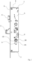
- the lock has a case 1 that houses the latch 4 and the bolt 2.
- the bolt 2 is actuatable by a cylinder 3 having a stator 3A and a rotor 3B provided with a slit 10 for inserting a key (not shown).
- the case 1 is formed by two parallel flat sides 5, a bottom 6, a base 7 and a cap 8.
- the case 1 is closed frontally by a plate 9 having suitable openings for extracting and retracting the bolt 2 and the latch 4.
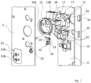
- a fixed support 12 and a rotatable follower 11 provided with a housing 13 for a square pin (not shown) for controlling retraction of the latch 4 into the case 1 to an opening position of the lock.
- the rotatable follower 11 is rotatable reversibly between a first limit stop 34 corresponding to the closed position of the lock closed by the latch 4 in which the latch 4 is protracted from the case 1 and a second limit stop 35 corresponding to the opening position of the lock opened by the latch 4.
- the limit stop 34 of the rotatable follower 11 is obtained on the fixed support 12.
- the limit stop 35 of the rotatable follower 11 is obtained on the case 1.
- the torsion spring 14 has a first end 14A rigidly coupled in rotation with the rotatable follower 11 and a second end 14B.
- the first end 14A of the spring 14 is formed by a spring 14 section turned towards the inside of the cylindrical generatrices of the coils of the spring 14, whereas the second end 14B of the spring 14 is formed by a section turned to the outside of the cylindrical generatrices of the coils of the spring 14.
- the spring 14 surrounds a protrusion 16 of the rotatable follower 11 in which the housing 13 is obtained.
- the protrusion 16 of the rotatable follower 11 has a split 17 in which the first end 14A of the spring 14 is engaged.
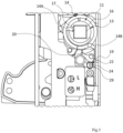
- the lock features mechanical adjusting means of the preload of the torsion spring 14 acting on the second end 14B of the torsion spring 14.
- the mechanical adjusting means comprises a movement element 18 of the operating position of the second end 14A of the spring 14.
- the movement element 18 is fitted rotatably in the case 1.
- the movement element 18 has a rotation movement receiving cam 19 and a movement cam 20 of the second end 14A of the spring 14 4.
- the mechanical adjusting means also comprises a suitable selector 22 interacting with the movement receiving cam 19 to move the movement element 18.
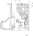
- the selector 22 has two selection positions to which two different positions of the second end 14A of the spring 14 4 correspond and consequently two different preload values of the spring 14 4.
- the mechanical adjusting means has two different configurations of stable equilibrium at the two selection positions of the selector 22.
- the selector 22 is fitted rotatably in the case 1.
- the selector 22 is nevertheless accessible through a window 23 of the case 1 to perform the selection.
- the selector 22 has a selection notch 24 that is engageable by a tool that is accessible through the window 23 of the case 1.
- the selection can be made using the tip of a screwdriver.
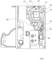
- the movement element 18 and the selector 22 are rotatable around respective fixed rotation axes 25, 26 parallel to the fixed rotation axis 27 of the rotatable follower 11.
- Such rotation axes 25, 26, 27 are orthogonal to the flat sides 5 of the case 1.
- the selector 22 has in particular a movement transfer cam 28 transferring movement to the movement receiving cam 19, and a first and a second plane 29, 30 that are mutually tilted and selectively engageable against an abutment plane 31 formed on the support 12.
- the abutment plane 31 defines a first rotation limit stop of the selector 22 when it engages the first plane 29 of the selector 22 at the first stable equilibrium configuration of the mechanical adjusting means and a second rotation limit stop of the selector 22 when it engages the second plane 30 of the selector 22 at the second stable equilibrium configuration of the mechanical adjusting means.
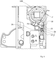
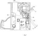
- the second end 14B of the spring 14 reacts on the movement element 18 with a force "Fm” with arm “a” relative to the rotation axis 25 of the movement element 18, and the thus urged movement element 18 in turn exerts on the selector 22 a force "Fb” with arm “b” relative to the rotation axis 26 of the selector 22.
- This force "Fb” generates torque that tends to rotate the selector 22 clockwise to the original selection position.
- Figure 7 shows that as the rotation of the selector 22 increases from the first selection position, the arm “b" of the force "Fb" decreases.
- the selector 22 then rotates to the second selection position because this time, compared to the cases illustrated above, the rotation of the selector 22 is sufficiently great to make the application direction of the force "Fb" travel through the rotation axis 26 of the selector 22.
- the second end 14B of the spring 14 then, through actuation of the selector 22, can be positioned stably only in the two operating positions.
- a label 33 is applied to the case 1, the label 33 showing two graphic reproductions 33A and 33B of the selector 22 in the two selection positions.
- the label 33 is staggered from the selector 22.
- the lock can be provided with the selector 22 in a default selection position, for example the first selection position, on which the approved graphic reproduction 33A, 33B of the selector 22 is superimposed.
- the installer for switching from the first to the second selection position, the installer necessarily has to bore the label 33 with the tip of the screwdriver.
- the materials used, as well as the dimensions, can be any depending on the needs and the state of the art.
Landscapes
- Engineering & Computer Science (AREA)
- Structural Engineering (AREA)
- Business, Economics & Management (AREA)
- Emergency Management (AREA)
- Mechanical Engineering (AREA)
- Closing And Opening Devices For Wings, And Checks For Wings (AREA)
- Lock And Its Accessories (AREA)
Claims (9)
- Ein Schloss für ein Fenster oder eine Tür, bestehend aus einem Gehäuse (1) und innerhalb des Gehäuses (1) einer festen Stütze (12), einer Riegel (4), der aus dem Gehäuse (1) in eine Schließposition des Schlosses herausziehbar ist, einem drehbaren Mitnehmer (11), der mit einer Aufnahme (13) für einen Vierkantstift zum Steuern des Zurückziehens des Riegels (4) in das Gehäuse (1) in eine Öffnungsposition des Schlosses versehen ist, einer automatischen Rückstell-Torsionsfeder (14) des drehbaren Mitnehmers (11), wobei die Torsionsfeder (14) ein erstes Ende (14A) aufweist, das drehfest mit dem drehbaren Mitnehmer (11) verbunden ist, und ein zweites Ende (14B), wobei weiterhin mechanische Einstellmittel der Vorspannung der Torsionsfeder (14) vorgesehen sind, die auf das zweite Ende (14B) der Torsionsfeder (14) einwirken, dadurch gekennzeichnet, dass die mechanischen Einstellmittel ein Bewegungselement (18) der Betriebsposition des zweiten Endes (14B) der Torsionsfeder (14) umfassen, wobei das Bewegungselement (18) eine Drehbewegungsaufnahme-Nocke (19) und eine Bewegungnocke (20) des zweiten Endes (14B) der Torsionsfeder (14) aufweist, wobei die mechanischen Einstellmittel ferner einen Selektor (22) umfassen, der mit der Drehbewegungsaufnahme-Nocke (19) interagiert, um das Bewegungselement (18) zu bewegen, wobei das Bewegungselement (18) und der Selektor (22) um jeweilige feste Drehachsen (25, 26) drehbar sind, die parallel zu einer festen Drehachse (27) des drehbaren Mitnehmers (11) verlaufen.
- Das Schloss für ein Fenster oder eine Tür nach einem der vorhergehenden Ansprüche, dadurch gekennzeichnet, dass die Feder (14) eine Ausstülpung (16) des drehbaren Mitnehmers (11) umgibt, in der die Aufnahme (13) eingebracht ist.
- Ein Schloss für ein Fenster oder eine Tür nach einem der vorhergehenden Ansprüche, dadurch gekennzeichnet, dass der Selektor (22) zwei Auswahlpositionen hat, denen zwei Betriebspositionen des zweiten Endes (14B) der Torsionsfeder (14) entsprechen.
- Das Schloss für ein Fenster oder eine Tür nach dem vorhergehenden Anspruch, dadurch gekennzeichnet, dass die Einstellmittel zwei stabile Gleichgewichtskonfigurationen in den beiden Auswahlpositionen aufweisen.
- Ein Schloss für ein Fenster oder eine Tür nach einem der vorhergehenden Ansprüche, dadurch gekennzeichnet, dass der Selektor (22) durch ein Fenster (23) des Gehäuses (1) zugänglich ist, um die Auswahl durchzuführen.
- Das Schloss für ein Fenster oder eine Tür nach dem vorhergehenden Anspruch, dadurch gekennzeichnet, dass der Selektor (22) eine Auswahlnut (24) hat.
- Das Schloss für ein Fenster oder eine Tür nach dem vorhergehenden Anspruch, dadurch gekennzeichnet, dass es auf dem Gehäuse (1) ein Etikett (33) hat, das zwei grafische Darstellungen (33A, 33B) des Selektors (22) in den beiden Auswahlpositionen zeigt.
- Ein Fenster oder eine Tür mit einem Griff, dadurch gekennzeichnet, dass es ein Schloss gemäß einem der vorhergehenden Ansprüche umfasst.
- Ein Fenster oder eine Tür mit einem Panikgriff, dadurch gekennzeichnet, dass es ein Schloss gemäß einem der Ansprüche 1 bis 7 umfasst.
Applications Claiming Priority (1)
| Application Number | Priority Date | Filing Date | Title |
|---|---|---|---|
| IT102022000007058A IT202200007058A1 (it) | 2022-04-08 | 2022-04-08 | Serratura per serramento |
Publications (3)
| Publication Number | Publication Date |
|---|---|
| EP4257786A1 EP4257786A1 (de) | 2023-10-11 |
| EP4257786C0 EP4257786C0 (de) | 2024-07-24 |
| EP4257786B1 true EP4257786B1 (de) | 2024-07-24 |
Family
ID=82308342
Family Applications (1)
| Application Number | Title | Priority Date | Filing Date |
|---|---|---|---|
| EP23163048.4A Active EP4257786B1 (de) | 2022-04-08 | 2023-03-21 | Schloss für ein fenster oder eine tür |
Country Status (3)
| Country | Link |
|---|---|
| EP (1) | EP4257786B1 (de) |
| ES (1) | ES2987389T3 (de) |
| IT (1) | IT202200007058A1 (de) |
Family Cites Families (5)
| Publication number | Priority date | Publication date | Assignee | Title |
|---|---|---|---|---|
| GB2323626B (en) * | 1997-03-25 | 2001-06-13 | Newman Tonks Group Plc | Latch assembly |
| DE102008021002A1 (de) * | 2008-04-25 | 2009-10-29 | Ceslocks Gmbh | Schlosseinsatz für ein Glastürschloss |
| AU2010333710B2 (en) * | 2009-12-18 | 2014-09-04 | Assa Abloy Australia Pty Limited | Adjustable mortice lock assembly |
| DE102010061516A1 (de) * | 2010-12-23 | 2012-06-28 | Dorma Gmbh + Co. Kg | Schloss für eine Tür, insbesondere für eine Ganzglastür |
| EP2503080B1 (de) * | 2011-03-21 | 2018-10-31 | Rohrbacher Schlosswarenfabrik Wilh. Grundmann Gesellschaft m.b.H. | Federklemmnuss |
-
2022
- 2022-04-08 IT IT102022000007058A patent/IT202200007058A1/it unknown
-
2023
- 2023-03-21 ES ES23163048T patent/ES2987389T3/es active Active
- 2023-03-21 EP EP23163048.4A patent/EP4257786B1/de active Active
Also Published As
| Publication number | Publication date |
|---|---|
| ES2987389T3 (es) | 2024-11-14 |
| IT202200007058A1 (it) | 2023-10-08 |
| EP4257786C0 (de) | 2024-07-24 |
| EP4257786A1 (de) | 2023-10-11 |
Similar Documents
| Publication | Publication Date | Title |
|---|---|---|
| EP2186974B1 (de) | Zylinderschloss mit schwenkbar montiertem Bolzen | |
| CN1067484C (zh) | 一种旋转开关的可闭锁的操纵装置 | |
| EP2224081B1 (de) | Verschluss für Schiebetür oder -tor | |
| AU2020278940B2 (en) | Catch mechanism for a locking device | |
| EP4257786B1 (de) | Schloss für ein fenster oder eine tür | |
| CN1126854C (zh) | 弹簧锁组件 | |
| AU2020309101B2 (en) | A lock body for a sliding door | |
| US12044036B2 (en) | Hub for lock device, and lock device | |
| JP2025507880A (ja) | 錠前装置およびロッキング装置 | |
| EP3262257B1 (de) | Universelles schloss mit einem gleitsperrmechanismus | |
| EP4575153A1 (de) | Verriegelung für ein schiebeverschlusselement und verschlusssystem damit | |
| AU2003203477B1 (en) | Latch assembly with dead latch indicator | |
| EP4112852A1 (de) | Exzenterverriegelungsmechanismus für ein elektronisches zylinderschloss und elektronisches zylinderschloss mit diesem verriegelungsmechanismus | |
| AU2018223215B2 (en) | Rim latch with safety release selectability | |
| WO2019143252A1 (en) | Electrical door strike functioning under pressure | |
| EP1505230A1 (de) | Schloss mit Drehfalle | |
| EP0922825B1 (de) | Vorrichtung zur Auswahl der Betätigungsrichtung eines Schlosses gemäss der Einbautürseite des Schlosses | |
| WO2025257028A1 (en) | Arrangement for lock device, and lock device | |
| KR100513549B1 (ko) | 도어 잠금장치 | |
| WO2025083685A1 (en) | Safe lock | |
| AU2023275956A1 (en) | Swing handle arrangement with a locking function | |
| WO2021018989A1 (en) | Electrically-operated lock | |
| NZ756436B2 (en) | Rim latch with safety release selectability | |
| GB2586018A (en) | Electrically-Operated Lock | |
| GB2260159A (en) | Bolt assembly |
Legal Events
| Date | Code | Title | Description |
|---|---|---|---|
| PUAI | Public reference made under article 153(3) epc to a published international application that has entered the european phase |
Free format text: ORIGINAL CODE: 0009012 |
|
| STAA | Information on the status of an ep patent application or granted ep patent |
Free format text: STATUS: THE APPLICATION HAS BEEN PUBLISHED |
|
| AK | Designated contracting states |
Kind code of ref document: A1 Designated state(s): AL AT BE BG CH CY CZ DE DK EE ES FI FR GB GR HR HU IE IS IT LI LT LU LV MC ME MK MT NL NO PL PT RO RS SE SI SK SM TR |
|
| STAA | Information on the status of an ep patent application or granted ep patent |
Free format text: STATUS: REQUEST FOR EXAMINATION WAS MADE |
|
| P01 | Opt-out of the competence of the unified patent court (upc) registered |
Effective date: 20231215 |
|
| 17P | Request for examination filed |
Effective date: 20240117 |
|
| RBV | Designated contracting states (corrected) |
Designated state(s): AL AT BE BG CH CY CZ DE DK EE ES FI FR GB GR HR HU IE IS IT LI LT LU LV MC ME MK MT NL NO PL PT RO RS SE SI SK SM TR |
|
| GRAP | Despatch of communication of intention to grant a patent |
Free format text: ORIGINAL CODE: EPIDOSNIGR1 |
|
| STAA | Information on the status of an ep patent application or granted ep patent |
Free format text: STATUS: GRANT OF PATENT IS INTENDED |
|
| RIC1 | Information provided on ipc code assigned before grant |
Ipc: E05B 15/00 20060101ALN20240219BHEP Ipc: E05B 15/04 20060101ALN20240219BHEP Ipc: E05B 59/00 20060101ALI20240219BHEP Ipc: E05C 1/16 20060101ALI20240219BHEP Ipc: E05B 65/10 20060101ALI20240219BHEP Ipc: E05B 63/00 20060101AFI20240219BHEP |
|
| INTG | Intention to grant announced |
Effective date: 20240326 |
|
| GRAS | Grant fee paid |
Free format text: ORIGINAL CODE: EPIDOSNIGR3 |
|
| GRAA | (expected) grant |
Free format text: ORIGINAL CODE: 0009210 |
|
| STAA | Information on the status of an ep patent application or granted ep patent |
Free format text: STATUS: THE PATENT HAS BEEN GRANTED |
|
| AK | Designated contracting states |
Kind code of ref document: B1 Designated state(s): AL AT BE BG CH CY CZ DE DK EE ES FI FR GB GR HR HU IE IS IT LI LT LU LV MC ME MK MT NL NO PL PT RO RS SE SI SK SM TR |
|
| REG | Reference to a national code |
Ref country code: GB Ref legal event code: FG4D |
|
| REG | Reference to a national code |
Ref country code: CH Ref legal event code: EP |
|
| REG | Reference to a national code |
Ref country code: DE Ref legal event code: R096 Ref document number: 602023000281 Country of ref document: DE |
|
| REG | Reference to a national code |
Ref country code: IE Ref legal event code: FG4D |
|
| U01 | Request for unitary effect filed |
Effective date: 20240725 |
|
| P04 | Withdrawal of opt-out of the competence of the unified patent court (upc) registered |
Free format text: CASE NUMBER: APP_45059/2024 Effective date: 20240803 |
|
| U07 | Unitary effect registered |
Designated state(s): AT BE BG DE DK EE FI FR IT LT LU LV MT NL PT SE SI Effective date: 20240807 |
|
| REG | Reference to a national code |
Ref country code: ES Ref legal event code: FG2A Ref document number: 2987389 Country of ref document: ES Kind code of ref document: T3 Effective date: 20241114 |
|
| P05 | Withdrawal of opt-out of the competence of the unified patent court (upc) changed |
Free format text: CASE NUMBER: APP_45059/2024 Effective date: 20240807 |
|
| PG25 | Lapsed in a contracting state [announced via postgrant information from national office to epo] |
Ref country code: NO Free format text: LAPSE BECAUSE OF FAILURE TO SUBMIT A TRANSLATION OF THE DESCRIPTION OR TO PAY THE FEE WITHIN THE PRESCRIBED TIME-LIMIT Effective date: 20241024 |
|
| PG25 | Lapsed in a contracting state [announced via postgrant information from national office to epo] |
Ref country code: GR Free format text: LAPSE BECAUSE OF FAILURE TO SUBMIT A TRANSLATION OF THE DESCRIPTION OR TO PAY THE FEE WITHIN THE PRESCRIBED TIME-LIMIT Effective date: 20241025 Ref country code: PL Free format text: LAPSE BECAUSE OF FAILURE TO SUBMIT A TRANSLATION OF THE DESCRIPTION OR TO PAY THE FEE WITHIN THE PRESCRIBED TIME-LIMIT Effective date: 20240724 |
|
| PG25 | Lapsed in a contracting state [announced via postgrant information from national office to epo] |
Ref country code: IS Free format text: LAPSE BECAUSE OF FAILURE TO SUBMIT A TRANSLATION OF THE DESCRIPTION OR TO PAY THE FEE WITHIN THE PRESCRIBED TIME-LIMIT Effective date: 20241124 |
|
| PG25 | Lapsed in a contracting state [announced via postgrant information from national office to epo] |
Ref country code: HR Free format text: LAPSE BECAUSE OF FAILURE TO SUBMIT A TRANSLATION OF THE DESCRIPTION OR TO PAY THE FEE WITHIN THE PRESCRIBED TIME-LIMIT Effective date: 20240724 |
|
| PG25 | Lapsed in a contracting state [announced via postgrant information from national office to epo] |
Ref country code: RS Free format text: LAPSE BECAUSE OF FAILURE TO SUBMIT A TRANSLATION OF THE DESCRIPTION OR TO PAY THE FEE WITHIN THE PRESCRIBED TIME-LIMIT Effective date: 20241024 |
|
| PG25 | Lapsed in a contracting state [announced via postgrant information from national office to epo] |
Ref country code: RS Free format text: LAPSE BECAUSE OF FAILURE TO SUBMIT A TRANSLATION OF THE DESCRIPTION OR TO PAY THE FEE WITHIN THE PRESCRIBED TIME-LIMIT Effective date: 20241024 Ref country code: PL Free format text: LAPSE BECAUSE OF FAILURE TO SUBMIT A TRANSLATION OF THE DESCRIPTION OR TO PAY THE FEE WITHIN THE PRESCRIBED TIME-LIMIT Effective date: 20240724 Ref country code: NO Free format text: LAPSE BECAUSE OF FAILURE TO SUBMIT A TRANSLATION OF THE DESCRIPTION OR TO PAY THE FEE WITHIN THE PRESCRIBED TIME-LIMIT Effective date: 20241024 Ref country code: IS Free format text: LAPSE BECAUSE OF FAILURE TO SUBMIT A TRANSLATION OF THE DESCRIPTION OR TO PAY THE FEE WITHIN THE PRESCRIBED TIME-LIMIT Effective date: 20241124 Ref country code: HR Free format text: LAPSE BECAUSE OF FAILURE TO SUBMIT A TRANSLATION OF THE DESCRIPTION OR TO PAY THE FEE WITHIN THE PRESCRIBED TIME-LIMIT Effective date: 20240724 Ref country code: GR Free format text: LAPSE BECAUSE OF FAILURE TO SUBMIT A TRANSLATION OF THE DESCRIPTION OR TO PAY THE FEE WITHIN THE PRESCRIBED TIME-LIMIT Effective date: 20241025 |
|
| U20 | Renewal fee for the european patent with unitary effect paid |
Year of fee payment: 3 Effective date: 20250305 |
|
| PG25 | Lapsed in a contracting state [announced via postgrant information from national office to epo] |
Ref country code: SM Free format text: LAPSE BECAUSE OF FAILURE TO SUBMIT A TRANSLATION OF THE DESCRIPTION OR TO PAY THE FEE WITHIN THE PRESCRIBED TIME-LIMIT Effective date: 20240724 |
|
| PG25 | Lapsed in a contracting state [announced via postgrant information from national office to epo] |
Ref country code: CZ Free format text: LAPSE BECAUSE OF FAILURE TO SUBMIT A TRANSLATION OF THE DESCRIPTION OR TO PAY THE FEE WITHIN THE PRESCRIBED TIME-LIMIT Effective date: 20240724 |
|
| PG25 | Lapsed in a contracting state [announced via postgrant information from national office to epo] |
Ref country code: SK Free format text: LAPSE BECAUSE OF FAILURE TO SUBMIT A TRANSLATION OF THE DESCRIPTION OR TO PAY THE FEE WITHIN THE PRESCRIBED TIME-LIMIT Effective date: 20240724 |
|
| PLBE | No opposition filed within time limit |
Free format text: ORIGINAL CODE: 0009261 |
|
| STAA | Information on the status of an ep patent application or granted ep patent |
Free format text: STATUS: NO OPPOSITION FILED WITHIN TIME LIMIT |
|
| 26N | No opposition filed |
Effective date: 20250425 |
|
| PGFP | Annual fee paid to national office [announced via postgrant information from national office to epo] |
Ref country code: ES Payment date: 20250417 Year of fee payment: 3 |
|
| PG25 | Lapsed in a contracting state [announced via postgrant information from national office to epo] |
Ref country code: MC Free format text: LAPSE BECAUSE OF FAILURE TO SUBMIT A TRANSLATION OF THE DESCRIPTION OR TO PAY THE FEE WITHIN THE PRESCRIBED TIME-LIMIT Effective date: 20240724 |
|
| PG25 | Lapsed in a contracting state [announced via postgrant information from national office to epo] |
Ref country code: IE Free format text: LAPSE BECAUSE OF NON-PAYMENT OF DUE FEES Effective date: 20250321 |
|
| PGFP | Annual fee paid to national office [announced via postgrant information from national office to epo] |
Ref country code: RO Payment date: 20260312 Year of fee payment: 4 |
|
| PGFP | Annual fee paid to national office [announced via postgrant information from national office to epo] |
Ref country code: TR Payment date: 20260305 Year of fee payment: 4 |