EP4257868B1 - Robinet pour récipient de gaz à détendeur intégré amélioré - Google Patents
Robinet pour récipient de gaz à détendeur intégré amélioré Download PDFInfo
- Publication number
- EP4257868B1 EP4257868B1 EP23154947.8A EP23154947A EP4257868B1 EP 4257868 B1 EP4257868 B1 EP 4257868B1 EP 23154947 A EP23154947 A EP 23154947A EP 4257868 B1 EP4257868 B1 EP 4257868B1
- Authority
- EP
- European Patent Office
- Prior art keywords
- valve
- gas
- chamber
- seat
- expansion
- Prior art date
- Legal status (The legal status is an assumption and is not a legal conclusion. Google has not performed a legal analysis and makes no representation as to the accuracy of the status listed.)
- Active
Links
Images



Classifications
-
- F—MECHANICAL ENGINEERING; LIGHTING; HEATING; WEAPONS; BLASTING
- F17—STORING OR DISTRIBUTING GASES OR LIQUIDS
- F17C—VESSELS FOR CONTAINING OR STORING COMPRESSED, LIQUEFIED OR SOLIDIFIED GASES; FIXED-CAPACITY GAS-HOLDERS; FILLING VESSELS WITH, OR DISCHARGING FROM VESSELS, COMPRESSED, LIQUEFIED, OR SOLIDIFIED GASES
- F17C13/00—Details of vessels or of the filling or discharging of vessels
- F17C13/04—Arrangement or mounting of valves
-
- F—MECHANICAL ENGINEERING; LIGHTING; HEATING; WEAPONS; BLASTING
- F17—STORING OR DISTRIBUTING GASES OR LIQUIDS
- F17C—VESSELS FOR CONTAINING OR STORING COMPRESSED, LIQUEFIED OR SOLIDIFIED GASES; FIXED-CAPACITY GAS-HOLDERS; FILLING VESSELS WITH, OR DISCHARGING FROM VESSELS, COMPRESSED, LIQUEFIED, OR SOLIDIFIED GASES
- F17C2201/00—Vessel construction, in particular geometry, arrangement or size
- F17C2201/01—Shape
- F17C2201/0104—Shape cylindrical
- F17C2201/0114—Shape cylindrical with interiorly curved end-piece
-
- F—MECHANICAL ENGINEERING; LIGHTING; HEATING; WEAPONS; BLASTING
- F17—STORING OR DISTRIBUTING GASES OR LIQUIDS
- F17C—VESSELS FOR CONTAINING OR STORING COMPRESSED, LIQUEFIED OR SOLIDIFIED GASES; FIXED-CAPACITY GAS-HOLDERS; FILLING VESSELS WITH, OR DISCHARGING FROM VESSELS, COMPRESSED, LIQUEFIED, OR SOLIDIFIED GASES
- F17C2201/00—Vessel construction, in particular geometry, arrangement or size
- F17C2201/03—Orientation
- F17C2201/032—Orientation with substantially vertical main axis
-
- F—MECHANICAL ENGINEERING; LIGHTING; HEATING; WEAPONS; BLASTING
- F17—STORING OR DISTRIBUTING GASES OR LIQUIDS
- F17C—VESSELS FOR CONTAINING OR STORING COMPRESSED, LIQUEFIED OR SOLIDIFIED GASES; FIXED-CAPACITY GAS-HOLDERS; FILLING VESSELS WITH, OR DISCHARGING FROM VESSELS, COMPRESSED, LIQUEFIED, OR SOLIDIFIED GASES
- F17C2201/00—Vessel construction, in particular geometry, arrangement or size
- F17C2201/05—Size
- F17C2201/058—Size portable (<30 l)
-
- F—MECHANICAL ENGINEERING; LIGHTING; HEATING; WEAPONS; BLASTING
- F17—STORING OR DISTRIBUTING GASES OR LIQUIDS
- F17C—VESSELS FOR CONTAINING OR STORING COMPRESSED, LIQUEFIED OR SOLIDIFIED GASES; FIXED-CAPACITY GAS-HOLDERS; FILLING VESSELS WITH, OR DISCHARGING FROM VESSELS, COMPRESSED, LIQUEFIED, OR SOLIDIFIED GASES
- F17C2205/00—Vessel construction, in particular mounting arrangements, attachments or identifications means
- F17C2205/01—Mounting arrangements
- F17C2205/0153—Details of mounting arrangements
- F17C2205/0157—Details of mounting arrangements for transport
- F17C2205/0165—Details of mounting arrangements for transport with handgrip
-
- F—MECHANICAL ENGINEERING; LIGHTING; HEATING; WEAPONS; BLASTING
- F17—STORING OR DISTRIBUTING GASES OR LIQUIDS
- F17C—VESSELS FOR CONTAINING OR STORING COMPRESSED, LIQUEFIED OR SOLIDIFIED GASES; FIXED-CAPACITY GAS-HOLDERS; FILLING VESSELS WITH, OR DISCHARGING FROM VESSELS, COMPRESSED, LIQUEFIED, OR SOLIDIFIED GASES
- F17C2205/00—Vessel construction, in particular mounting arrangements, attachments or identifications means
- F17C2205/01—Mounting arrangements
- F17C2205/0153—Details of mounting arrangements
- F17C2205/0188—Hanging up devices
-
- F—MECHANICAL ENGINEERING; LIGHTING; HEATING; WEAPONS; BLASTING
- F17—STORING OR DISTRIBUTING GASES OR LIQUIDS
- F17C—VESSELS FOR CONTAINING OR STORING COMPRESSED, LIQUEFIED OR SOLIDIFIED GASES; FIXED-CAPACITY GAS-HOLDERS; FILLING VESSELS WITH, OR DISCHARGING FROM VESSELS, COMPRESSED, LIQUEFIED, OR SOLIDIFIED GASES
- F17C2205/00—Vessel construction, in particular mounting arrangements, attachments or identifications means
- F17C2205/03—Fluid connections, filters, valves, closure means or other attachments
- F17C2205/0302—Fittings, valves, filters, or components in connection with the gas storage device
- F17C2205/0308—Protective caps
-
- F—MECHANICAL ENGINEERING; LIGHTING; HEATING; WEAPONS; BLASTING
- F17—STORING OR DISTRIBUTING GASES OR LIQUIDS
- F17C—VESSELS FOR CONTAINING OR STORING COMPRESSED, LIQUEFIED OR SOLIDIFIED GASES; FIXED-CAPACITY GAS-HOLDERS; FILLING VESSELS WITH, OR DISCHARGING FROM VESSELS, COMPRESSED, LIQUEFIED, OR SOLIDIFIED GASES
- F17C2205/00—Vessel construction, in particular mounting arrangements, attachments or identifications means
- F17C2205/03—Fluid connections, filters, valves, closure means or other attachments
- F17C2205/0302—Fittings, valves, filters, or components in connection with the gas storage device
- F17C2205/0323—Valves
- F17C2205/0329—Valves manually actuated
-
- F—MECHANICAL ENGINEERING; LIGHTING; HEATING; WEAPONS; BLASTING
- F17—STORING OR DISTRIBUTING GASES OR LIQUIDS
- F17C—VESSELS FOR CONTAINING OR STORING COMPRESSED, LIQUEFIED OR SOLIDIFIED GASES; FIXED-CAPACITY GAS-HOLDERS; FILLING VESSELS WITH, OR DISCHARGING FROM VESSELS, COMPRESSED, LIQUEFIED, OR SOLIDIFIED GASES
- F17C2205/00—Vessel construction, in particular mounting arrangements, attachments or identifications means
- F17C2205/03—Fluid connections, filters, valves, closure means or other attachments
- F17C2205/0302—Fittings, valves, filters, or components in connection with the gas storage device
- F17C2205/0323—Valves
- F17C2205/0332—Safety valves or pressure relief valves
-
- F—MECHANICAL ENGINEERING; LIGHTING; HEATING; WEAPONS; BLASTING
- F17—STORING OR DISTRIBUTING GASES OR LIQUIDS
- F17C—VESSELS FOR CONTAINING OR STORING COMPRESSED, LIQUEFIED OR SOLIDIFIED GASES; FIXED-CAPACITY GAS-HOLDERS; FILLING VESSELS WITH, OR DISCHARGING FROM VESSELS, COMPRESSED, LIQUEFIED, OR SOLIDIFIED GASES
- F17C2205/00—Vessel construction, in particular mounting arrangements, attachments or identifications means
- F17C2205/03—Fluid connections, filters, valves, closure means or other attachments
- F17C2205/0302—Fittings, valves, filters, or components in connection with the gas storage device
- F17C2205/0338—Pressure regulators
-
- F—MECHANICAL ENGINEERING; LIGHTING; HEATING; WEAPONS; BLASTING
- F17—STORING OR DISTRIBUTING GASES OR LIQUIDS
- F17C—VESSELS FOR CONTAINING OR STORING COMPRESSED, LIQUEFIED OR SOLIDIFIED GASES; FIXED-CAPACITY GAS-HOLDERS; FILLING VESSELS WITH, OR DISCHARGING FROM VESSELS, COMPRESSED, LIQUEFIED, OR SOLIDIFIED GASES
- F17C2205/00—Vessel construction, in particular mounting arrangements, attachments or identifications means
- F17C2205/03—Fluid connections, filters, valves, closure means or other attachments
- F17C2205/0302—Fittings, valves, filters, or components in connection with the gas storage device
- F17C2205/0382—Constructional details of valves, regulators
- F17C2205/0385—Constructional details of valves, regulators in blocks or units
-
- F—MECHANICAL ENGINEERING; LIGHTING; HEATING; WEAPONS; BLASTING
- F17—STORING OR DISTRIBUTING GASES OR LIQUIDS
- F17C—VESSELS FOR CONTAINING OR STORING COMPRESSED, LIQUEFIED OR SOLIDIFIED GASES; FIXED-CAPACITY GAS-HOLDERS; FILLING VESSELS WITH, OR DISCHARGING FROM VESSELS, COMPRESSED, LIQUEFIED, OR SOLIDIFIED GASES
- F17C2221/00—Handled fluid, in particular type of fluid
- F17C2221/01—Pure fluids
- F17C2221/011—Oxygen
-
- F—MECHANICAL ENGINEERING; LIGHTING; HEATING; WEAPONS; BLASTING
- F17—STORING OR DISTRIBUTING GASES OR LIQUIDS
- F17C—VESSELS FOR CONTAINING OR STORING COMPRESSED, LIQUEFIED OR SOLIDIFIED GASES; FIXED-CAPACITY GAS-HOLDERS; FILLING VESSELS WITH, OR DISCHARGING FROM VESSELS, COMPRESSED, LIQUEFIED, OR SOLIDIFIED GASES
- F17C2221/00—Handled fluid, in particular type of fluid
- F17C2221/01—Pure fluids
- F17C2221/014—Nitrogen
-
- F—MECHANICAL ENGINEERING; LIGHTING; HEATING; WEAPONS; BLASTING
- F17—STORING OR DISTRIBUTING GASES OR LIQUIDS
- F17C—VESSELS FOR CONTAINING OR STORING COMPRESSED, LIQUEFIED OR SOLIDIFIED GASES; FIXED-CAPACITY GAS-HOLDERS; FILLING VESSELS WITH, OR DISCHARGING FROM VESSELS, COMPRESSED, LIQUEFIED, OR SOLIDIFIED GASES
- F17C2221/00—Handled fluid, in particular type of fluid
- F17C2221/01—Pure fluids
- F17C2221/016—Noble gases (Ar, Kr, Xe)
- F17C2221/017—Helium
-
- F—MECHANICAL ENGINEERING; LIGHTING; HEATING; WEAPONS; BLASTING
- F17—STORING OR DISTRIBUTING GASES OR LIQUIDS
- F17C—VESSELS FOR CONTAINING OR STORING COMPRESSED, LIQUEFIED OR SOLIDIFIED GASES; FIXED-CAPACITY GAS-HOLDERS; FILLING VESSELS WITH, OR DISCHARGING FROM VESSELS, COMPRESSED, LIQUEFIED, OR SOLIDIFIED GASES
- F17C2221/00—Handled fluid, in particular type of fluid
- F17C2221/03—Mixtures
-
- F—MECHANICAL ENGINEERING; LIGHTING; HEATING; WEAPONS; BLASTING
- F17—STORING OR DISTRIBUTING GASES OR LIQUIDS
- F17C—VESSELS FOR CONTAINING OR STORING COMPRESSED, LIQUEFIED OR SOLIDIFIED GASES; FIXED-CAPACITY GAS-HOLDERS; FILLING VESSELS WITH, OR DISCHARGING FROM VESSELS, COMPRESSED, LIQUEFIED, OR SOLIDIFIED GASES
- F17C2221/00—Handled fluid, in particular type of fluid
- F17C2221/03—Mixtures
- F17C2221/031—Air
-
- F—MECHANICAL ENGINEERING; LIGHTING; HEATING; WEAPONS; BLASTING
- F17—STORING OR DISTRIBUTING GASES OR LIQUIDS
- F17C—VESSELS FOR CONTAINING OR STORING COMPRESSED, LIQUEFIED OR SOLIDIFIED GASES; FIXED-CAPACITY GAS-HOLDERS; FILLING VESSELS WITH, OR DISCHARGING FROM VESSELS, COMPRESSED, LIQUEFIED, OR SOLIDIFIED GASES
- F17C2223/00—Handled fluid before transfer, i.e. state of fluid when stored in the vessel or before transfer from the vessel
- F17C2223/01—Handled fluid before transfer, i.e. state of fluid when stored in the vessel or before transfer from the vessel characterised by the phase
- F17C2223/0107—Single phase
- F17C2223/0123—Single phase gaseous, e.g. CNG, GNC
-
- F—MECHANICAL ENGINEERING; LIGHTING; HEATING; WEAPONS; BLASTING
- F17—STORING OR DISTRIBUTING GASES OR LIQUIDS
- F17C—VESSELS FOR CONTAINING OR STORING COMPRESSED, LIQUEFIED OR SOLIDIFIED GASES; FIXED-CAPACITY GAS-HOLDERS; FILLING VESSELS WITH, OR DISCHARGING FROM VESSELS, COMPRESSED, LIQUEFIED, OR SOLIDIFIED GASES
- F17C2223/00—Handled fluid before transfer, i.e. state of fluid when stored in the vessel or before transfer from the vessel
- F17C2223/03—Handled fluid before transfer, i.e. state of fluid when stored in the vessel or before transfer from the vessel characterised by the pressure level
- F17C2223/036—Very high pressure (>80 bar)
-
- F—MECHANICAL ENGINEERING; LIGHTING; HEATING; WEAPONS; BLASTING
- F17—STORING OR DISTRIBUTING GASES OR LIQUIDS
- F17C—VESSELS FOR CONTAINING OR STORING COMPRESSED, LIQUEFIED OR SOLIDIFIED GASES; FIXED-CAPACITY GAS-HOLDERS; FILLING VESSELS WITH, OR DISCHARGING FROM VESSELS, COMPRESSED, LIQUEFIED, OR SOLIDIFIED GASES
- F17C2227/00—Transfer of fluids, i.e. method or means for transferring the fluid; Heat exchange with the fluid
- F17C2227/04—Methods for emptying or filling
- F17C2227/048—Methods for emptying or filling by maintaining residual pressure
-
- F—MECHANICAL ENGINEERING; LIGHTING; HEATING; WEAPONS; BLASTING
- F17—STORING OR DISTRIBUTING GASES OR LIQUIDS
- F17C—VESSELS FOR CONTAINING OR STORING COMPRESSED, LIQUEFIED OR SOLIDIFIED GASES; FIXED-CAPACITY GAS-HOLDERS; FILLING VESSELS WITH, OR DISCHARGING FROM VESSELS, COMPRESSED, LIQUEFIED, OR SOLIDIFIED GASES
- F17C2250/00—Accessories; Control means; Indicating, measuring or monitoring of parameters
- F17C2250/04—Indicating or measuring of parameters as input values
- F17C2250/0404—Parameters indicated or measured
- F17C2250/043—Pressure
-
- F—MECHANICAL ENGINEERING; LIGHTING; HEATING; WEAPONS; BLASTING
- F17—STORING OR DISTRIBUTING GASES OR LIQUIDS
- F17C—VESSELS FOR CONTAINING OR STORING COMPRESSED, LIQUEFIED OR SOLIDIFIED GASES; FIXED-CAPACITY GAS-HOLDERS; FILLING VESSELS WITH, OR DISCHARGING FROM VESSELS, COMPRESSED, LIQUEFIED, OR SOLIDIFIED GASES
- F17C2250/00—Accessories; Control means; Indicating, measuring or monitoring of parameters
- F17C2250/04—Indicating or measuring of parameters as input values
- F17C2250/0404—Parameters indicated or measured
- F17C2250/0439—Temperature
-
- F—MECHANICAL ENGINEERING; LIGHTING; HEATING; WEAPONS; BLASTING
- F17—STORING OR DISTRIBUTING GASES OR LIQUIDS
- F17C—VESSELS FOR CONTAINING OR STORING COMPRESSED, LIQUEFIED OR SOLIDIFIED GASES; FIXED-CAPACITY GAS-HOLDERS; FILLING VESSELS WITH, OR DISCHARGING FROM VESSELS, COMPRESSED, LIQUEFIED, OR SOLIDIFIED GASES
- F17C2270/00—Applications
- F17C2270/02—Applications for medical applications
- F17C2270/025—Breathing
Definitions
- the invention relates to an integrated pressure reducing valve (IRV) for a pressurized gas container, as well as to a pressurized gas container, such as a medical oxygen cylinder equipped with such an IRV and its use for storing a gas or gas mixture under pressure, in particular oxygen.
- IRV integrated pressure reducing valve
- An integrated pressure reducing valve (IRV) fitted to a pressurized gas container, such as a gas cylinder, allows not only the release of the pressurized gas to be controlled but also the subsequent distribution of the gas at reduced pressure, i.e. its flow rate.
- expansion means are integrated into the body of the valve. They are arranged on the internal gas circuit of the RDI which carries the gas from an inlet in fluid communication with the pressurized gas container and a gas outlet carried by an outlet connector, i.e. a nozzle, or the like.
- an outlet connector i.e. a nozzle, or the like.
- the expansion means usually comprise a movable expansion valve cooperating with a valve seat to operate the expansion of the gas, that is to say to reduce its pressure level from a so-called “high” pressure or high pressure (HP) corresponding to the pressure of the gas when it is compressed in the container, to a so-called “low” pressure or low pressure (LP) corresponding to the operating pressure, that is to say a LP pressure lower than the high pressure HP, for example an HP between 100 and 300 bar abs (for a full container) and a LP obtained after expansion, lower than 10 bar abs.
- HP high pressure
- LP low pressure
- FR-A-3002614 US-A-2008/0105309 And FR-A-2979718 which describe valves with integrated pressure regulator (RDI), in particular for pressurized gas containers, in accordance with the preamble of claim 1.
- RDI integrated pressure regulator
- a problem is therefore to propose an improved integrated pressure reducing valve or RDI, i.e. making it possible to avoid the aforementioned disadvantages affecting the pressure reducing valve and the valve seat.
- a sealing element is arranged between the seat element and the bottom or an inner wall of the first chamber.
- the invention further relates to a pressurized gas container comprising an integrated pressure reducing valve (IRV) according to the invention, in particular a gas cylinder.
- IOV integrated pressure reducing valve
- the gas container comprises a protective cover arranged around the RDI so as to protect it against impacts or the like.
- the invention further relates to a use of a pressurized gas container, in particular a gas cylinder, equipped with an RDI according to the invention for storing a gas or a gas mixture chosen from oxygen, air, N 2 O/O 2 , He/O 2 , NO/nitrogen, typically oxygen.
- a pressurized gas container in particular a gas cylinder, equipped with an RDI according to the invention for storing a gas or a gas mixture chosen from oxygen, air, N 2 O/O 2 , He/O 2 , NO/nitrogen, typically oxygen.
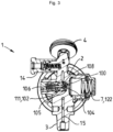
- Fig. 1 and Fig. 2 represent an embodiment of an integrated pressure reducing valve 1 or RDI according to the invention used for gas distribution, which comprises a valve body 2 formed of metal, for example brass, namely a CuZn40Pb2 alloy or other.
- the RDI 1 comprises, as detailed below, gas expansion means 100, i.e. pressure reduction means, making it possible to operate an expansion of the pressurized gas, i.e. a reduction in the pressure of the gas from a high pressure value of several tens, or even hundreds of bar abs, to a low pressure value, i.e. an expansion pressure level.
- the expansion pressure level i.e. after pressure reduction, can be fixed or adjusted by means of the pressure reduction means 100, as explained below with reference to the Fig. 3 to Fig. 5 , for example of the order of a few bars (ie ⁇ 10 bar abs), for example of the order of 4.5 bar abs.
- the valve body 2 is crossed by an internal gas circuit, that is to say one or more passages or conduits, making it possible to convey the gas, namely the high-pressure gas and the expanded gas, between a fluid inlet 10 carried by an expansion or threaded end piece 3, of cylindrical or truncated shape, used to fix the RDI 1 on a gas bottle 50 as illustrated in Fig. 6 , and a fluid outlet 40, namely a flow outlet 11, carried by a first outlet connector 12 supplying low pressure gas (LP).
- an internal gas circuit that is to say one or more passages or conduits, making it possible to convey the gas, namely the high-pressure gas and the expanded gas, between a fluid inlet 10 carried by an expansion or threaded end piece 3, of cylindrical or truncated shape, used to fix the RDI 1 on a gas bottle 50 as illustrated in Fig. 6 , and a fluid outlet 40, namely a flow outlet 11, carried by a first outlet connector 12 supplying low pressure gas (LP).
- LP low pressure gas
- the threaded end piece 3 allows the body 2 of the tap to be screwed onto a gas container 50, such as a gas bottle, as illustrated in Fig. 2 , containing the gas under pressure, i.e. at high pressure, in its ogive body 51 (partially visible) comprising an internal volume supplying the RDI 1.
- a gas container 50 such as a gas bottle, as illustrated in Fig. 2
- the gas under pressure i.e. at high pressure
- the body 2 of the RDI 1 can also comprise another fluid outlet 13, typically a so-called pressure outlet, carried by another outlet connector 14, which supplies the non-expanded gas, i.e. at high pressure.
- another fluid outlet 13 typically a so-called pressure outlet, carried by another outlet connector 14, which supplies the non-expanded gas, i.e. at high pressure.
- the gas expansion means 100 also called pressure reduction means, are arranged on the internal gas circuit 15 of the body 2, between the gas inlet 10 of the RDI 1 and the low pressure (LP) gas outlet 11, also called the flow outlet, carried by the outlet connector 12, i.e. the flow outlet connector.
- LP low pressure
- the outlet fittings 12, 14 are formed of a metal, such as a copper alloy, in particular brass, for example an alloy of the CuZn39Pb3 type. They have generally tubular shapes, i.e. elongated with axial passage for the gas communicating fluidically with the internal fluid circuit of the body 2 and opening at the outlet orifices 11, 13.
- the body 2 of the RDI 1 is also equipped with a pressure gauge 4 making it possible to visualize the pressure of the gas in the internal gas circuit 15 of the body 2, upstream of the expansion means 100 so as to reflect the residual pressure within the internal volume of the container 50 of pressurized gas.
- pressure gauge 4 is of the needle type, whereas on the Fig. 6 , the pressure gauge 4 is digital, that is to say that it is an electronic device with a digital display, implementing one (or more) microprocessors associated with one or more temperature and/or pressure sensors and making it possible to determine the gas pressure, or even other quantities, such as a gas autonomy or a volume of residual gas in the container 50, then to display them on the digital display.
- the body 2 of RDI 1 also carries a flow adjustment member 5, such as a rotary handwheel, cooperating with flow control means so as to allow a user to adjust the flow rate of fluid delivered by the fluid distribution connector 12, typically flow rates between 0 and 30 L/min, preferably between 0 and 15 L/min, or even 20 L/min.
- the flow control means may comprise, for example, a disk with calibrated orifices of different dimensions, i.e. diameters, which correspond to the different selectable gas flow rates.
- the flow adjustment member 5 is a rotary handwheel that can be manipulated by the user, which is arranged around and coaxially with the fluid distribution connector 41.
- the rotary handwheel 5 has the general shape of a graduated crown marked by flow rate indications. It comprises housings that are angularly offset from each other and sized to allow a user to insert fingers therein to exert a movement to turn the rotary handwheel 5 clockwise or counterclockwise to set the desired gas flow rate.
- the outlet connector 12 carrying the low pressure gas outlet 11 is arranged in the center of the rotary handwheel 5; however, the outlet connector 12 could be arranged elsewhere.
- the tap body 2 also comprises other components, such as a filling connection 6, i.e. an additional connection, configured to receive a filling socket which is connected thereto mechanically and fluidically in order to allow fresh fluid to be introduced into the internal volume of the fluid container 50 when it is empty for example.
- This filling connection comprises a filling valve preventing, in normal times, the fluid from escaping through this connection.
- the filling connection is in fluid communication with the internal volume of the container 50 via the internal gas circuit 15 of the body 2 of the RDI 1 and the inlet orifice 10 carried by the threaded end piece 3.
- the valve body 2 may also comprise a residual pressure mechanism (not shown) for ensuring or maintaining a minimum positive pressure in the container 50 by preventing total emptying thereof, i.e. total withdrawal of the fluid, as well as a safety valve 7 including the expansion piston 122, as explained below, for evacuating any excessive pressure in the gas circuit 15 of the valve body 2, i.e. for evacuating to the atmosphere any pressure greater than a safety threshold value, for example in the event of an internal leak in the valve body 2.
- a residual pressure mechanism (not shown) for ensuring or maintaining a minimum positive pressure in the container 50 by preventing total emptying thereof, i.e. total withdrawal of the fluid, as well as a safety valve 7 including the expansion piston 122, as explained below, for evacuating any excessive pressure in the gas circuit 15 of the valve body 2, i.e. for evacuating to the atmosphere any pressure greater than a safety threshold value, for example in the event of an internal leak in the valve body 2.
- Fig. 6 schematizes an RDI 1 according to the invention mounted on a fluid container 50 of the gas bottle type in the shape of an ogive, that is to say with a container body 51 of cylindrical shape (of axis AA) comprising a narrowed end forming a neck carrying a threaded opening communicating fluidly with the internal volume of the gas bottle.
- the RDI 1 is fixed by screwing, via its threaded end piece 3, into the threaded opening of the neck of the fluid container 50.
- the hollow cylindrical body of the container 60 comprises an internal volume used to contain the gas under pressure, that is to say at high pressure, typically a compressed medical gas, such as oxygen, at a pressure which can reach 180 to 300 bar abs, or more (when the bottle is full).
- the internal volume can have a capacity of 0.5 to 10 L (water equiv.), for example 2 L, 5 L or 7 L. Its diameter is of the order of 10 to 20 cm, typically of the order of 12 to 16 cm, for example around 14 cm.
- a protective cover 55 comprising a rigid body, made of polymer or metal, defining a protective enclosure in which the body 2 of the RDI 1 tap (not visible) is positioned and fixed to it or to the neck of the bottle 50 by its base 56.
- the cowling 55 further comprises a carrying handle 58 surmounting the body and connected to the latter by support uprights 59 in order to allow a user to manually lift and transport the cowling/RDI/bottle assembly 55, 1, 50.
- the carrying handle 58 is located opposite the base 56 relative to the cowling body.
- a pivoting attachment device 57 (partially visible) is also provided, located here opposite the outlet connector 11 of the RDI 1.
- This pivoting attachment device 57 is used to attach the cowling/RDI/bottle assembly to a hospital bed or stretcher bar or any other similar support, for example a rod or the like.
- the attachment device 57 can pivot, when unfolded by the user, between a folded position or rest position, in which it is positioned along the cowling body, as illustrated in Fig. 2 , and an unfolded position or hooking position, in which the hooking device 57 is pivoted and angularly spaced from the cover body so as to allow its lashing or hooking to a bed bar or the like.
- Such a pivoting hooking device 57 is described by EP-A-2918893
- the pressurized gas is introduced into the internal volume, when filling the container 50, via the filling connector 7 and the upstream portion of the internal circuit 15 of the RDI 1 and through the neck of the container 50.
- the extraction of the pressurized gas, when drawing off, is done in the opposite direction.
- flexible pipes made of metal or plastic, or other interfaces or devices may be connected and disconnected to the connector(s) 12, 14 of the RDI 1, which may be nickel-plated, i.e. covered with a nickel-based coating deposited on the brass forming these connectors 12, 14.
- Fig. 3 to Fig. 5 are cross-sectional diagrams of the pressure reduction means 100 of the RDI 1 according to the invention.
- these gas expansion means 100 are arranged on the internal gas circuit 15 passing through the body 2 of the RDI 1 and serve to operate a reduction in the pressure of the pressurized gas, i.e. an expansion of the gas, circulating in the gas circuit 15 and to obtain an expanded gas, i.e. at reduced pressure.
- the pressurized gas passes from the high pressure (i.e. which is equivalent to the pressure in the bottle) to a pre-set low pressure, typically less than 10 bars abs.
- the gas expansion means 100 arranged in the body 2 of the RDI 1 comprise a movable expansion valve 101 cooperating with a valve seat 102 to operate a gas expansion.
- the expansion valve 101 is carried by a valve rod 111 which is normally pushed towards the valve seat 102 by a valve spring or expansion spring 106, via an actuating part 112 arranged between the valve spring 106 and the valve rod 111 carrying the expansion valve 101.
- the valve spring 106 therefore presses on the actuating part 112 and the latter itself presses on the rear part 111b of the valve rod 111.
- the valve spring 106 has a spring body formed of coils and of generally cylindrical shape, while the actuating part 112 comprises a tubular body which is housed in the center of the cylinder forming the body of the spring 106 and a radial shoulder at the free end of the tubular body on which the terminal end of the body of the cylindrical spring 106 rests.
- the terminal end of the rear part 111b of the valve rod 111 is housed in the front face of the actuating part 112.
- the actuating part 112 and the trigger spring 106 are arranged in the internal compartment 113b of a hollow housing part 113 comprising a front bore 113a crossed by the rear part 111b of the valve rod 111.
- the housing part 113 is itself held in position by a cover part 114 which is fixed to the housing part 113 like a sleeve.
- the cover part 114 also forms a bottom wall for closing the internal compartment 113b of the housing part 113 which houses
- valve stem 111 and the expansion valve 101 therefore form a valve assembly 101, 111 that is axially movable (axis XX) within a first chamber 107 or high-pressure chamber of the body 2 of the RDI 1 that is supplied with high-pressure (HP) gas. More specifically, the valve assembly 101, 111 is movable while being guided by a guide piece 108 arranged within the first chamber 107.
- the rear portion 111b of the valve stem 111 and the expansion valve 101 are arranged in a valve chamber 118 of the guide piece 108, which valve chamber 118 is open facing a seat element 104 with which the expansion valve 101 cooperates, as explained below.
- the first chamber 107 or high pressure chamber of the body 2 of the RDI 1 is supplied with high pressure (HP) gas which enters it through an HP gas supply port 119. It communicates fluidically with a second chamber 109 or low pressure (LP) chamber of the body 2 of the RDI 1, via a connecting channel 110 for the expanded gas connecting these two chambers 107, 109 comprising an inlet port 110a communicating fluidically with the first chamber 107 and an outlet port 110b communicating fluidically with the second chamber 109.
- HP high pressure
- LP low pressure
- the first chamber 107 comprises a seat element 104, arranged in the bottom 117 of the first chamber 10 where the inlet orifice 100a of the connecting channel 110 opens.
- the seat element 104 is pierced with a gas passage 103 passing right through the seat element 104 which is arranged coaxially with the connecting channel 110 connecting the two chambers 107, 109.
- the valve seat 102 is formed on the periphery 103a of the inlet orifice of the gas passage 103, that is to say that the valve seat 102 is circular/annular.
- the seat element 104 is a part made of polymer material, for example a polymer of the polyamide or polyimide type, the polymer fibers of which are oriented axially along the axis XX.
- polymer material for example a polymer of the polyamide or polyimide type, the polymer fibers of which are oriented axially along the axis XX.
- orientation of the polymer fibers makes it possible to minimize the mechanical compression stresses applied to the valve seat 102 while ensuring a maximum compression ratio.
- the polymer part forming the seat element 104 is obtained for example by extrusion of the raw material and machining to obtain the shape.
- the seat element 104 is a part of revolution having here a general shape of a disc pierced in its center by the gas passage 103, i.e. substantially a washer shape, and comprising a groove or a peripheral or similar shoulder 104c on its external perimeter serving to house a sealing element 105, as visible in Fig. 4 and Fig. 5 .
- the seat element 104 has for example an external diameter between 4 and 20 mm, a thickness between 1 and 6 mm, and an internal diameter of the gas passage 103 between 0.5 and 5 mm.
- the guide part 108 comes to bear axially, via its front face 108a, on the rear face 104a of the seat element 104 to push it back into the blind bottom 117 and therefore hold it in place.
- the front face 104b of the seat element 104 therefore comes to rest on the blind bottom 117 and the sealing element 105, such as an O-ring, is then positioned and itself held between the seat element 104 and the side wall and/or the blind bottom 117 of the first chamber 107, within the peripheral groove or the shoulder 104c or the like.
- the rear face 108b of the guide part 108 is itself in contact with the housing part 113.
- the housing part 113 holds the guide part 108 by pushing it axially (axis XX) towards the seat element 104.
- sealing means 130 such as O-rings, are provided to ensure a gas seal between the housing part 113 and the guide part 108, and between the housing part 113 and the cover part 114.
- a front portion 111a of the valve rod 111 is movable within the gas passage 103 and the connecting channel 110 so that the expansion valve 101, which is carried by the valve rod 111, can come to cooperate with the valve seat 102 formed on the periphery 103a of the inlet orifice of the gas passage 103 (cf. Fig. 7 ) in order to adjust the trigger, that is, the level of trigger pressure, when the expansion valve 101 is slightly detached from the valve seat 102 or, conversely, ensure a gas seal between the valve 101 and the seat 102 when they are in contact with each other.
- a small spacing 141 i.e. a clearance, between the external peripheral surface (i.e. the perimeter) of the seat element 104 and the cylindrical internal wall of the guide part 108.
- This spacing 141 will allow the seat element 104 to be well positioned relative to the valve 101 by offering it lateral movement when it is subjected to the elastic force of the expansion spring 106, i.e. the axial action (XX) of the expansion spring 106 which is directed towards the seat element 104.
- XX axial action
- the inlet of the gas passage 103 is shaped to be flared, i.e. frustoconical.
- the expansion valve 101 must have a shape complementary to the valve seat 102 in order to ensure effective expansion or, conversely, a gas seal, when no expansion is desired. Consequently, the valve seat 102 which is formed on the periphery 103a of the inlet orifice of the gas passage 103 also has a circular shape, or even slightly frustoconical.
- the expansion valve 101 must also have a complementary frustoconical shape in order to be able to penetrate (partially) into the gas passage 103 of the seat element 104, through the inlet of said gas passage 103, and so that its external peripheral surface can cooperate with the circular shape, or even frustoconical, of the valve seat 102.
- the trigger pressure is adjusted by a trigger adjustment system 120 comprising a trigger piston 121 comprising an active part or front shield 122 and a piston spring 123 associated with said trigger piston 121, which are arranged in the second chamber 109 provided in the body of the RDI 1, which is open to the outside so as to be able to insert the various elements of the trigger adjustment system 120 therein.
- the expansion piston 121 comprises a piston body 121a of generally cylindrical shape bearing a peripheral annular shoulder 121b extending radially on which the proximal end 123a of the piston spring 123 which is arranged as a sleeve around the cylindrical piston body 121a comes to bear.
- the piston spring 123 then normally pushes the expansion piston 121 towards the connecting channel 110 opening into the second chamber 109 through which the low-pressure (LP) gas passes.
- LP low-pressure
- a rear cover 124 in the shape of a bell, cup or the like makes it possible to house and maintain the various elements 121-123 of the relaxation adjustment system 120 within the second chamber 109 arranged in the body 2 of the RDI 1, as visible in Fig. 5 .
- the distal end 123b of the piston spring 123 comes to bear in the bottom 124a of the rear cover 124.
- the rear cover 124 further comprises a thread 125 on its internal wall which comes to be fixed by screwing to a complementary thread 2a provided on the body 2 of the RDI 1, as illustrated in Fig. 5 .
- the rear cover 124, the expansion piston 121, the piston spring 123 and the front shield 122 are arranged coaxially within the second chamber 109 and also coaxial with the expansion valve 101, the valve rod 111, the expansion spring 106 and the seat member 104, as shown in Fig. 4 and Fig. 5 .
- the expansion piston 121 can be moved more or less within the second chamber 109 along the axis XX, that is to say towards or away from the connecting channel 110 opening into the second chamber 109, which makes it possible to adjust the desired pressure level.
- the front part 111a of the valve rod 111 which is movable within the gas passage 103 and the connecting channel 110, projects axially (axis XX) into the second chamber 109 and is in contact with the front shield 122 of the piston of relaxation 121.
- the front shield 122 of the relaxation piston 121 then cooperates with the free end 111c of the front part 111a of the valve rod 111 which projects into the second chamber 109, to push it more or less in the direction of the connecting channel 110, depending on the more or less significant screwing (i.e. clockwise or counterclockwise) applied to the rear cover 124, which makes it possible to adjust the relaxation level.
- any axial movement of the valve rod 111 generates an equal axial movement of the relaxation valve 101 which is carried by the valve rod 111, therefore a proportional separation or distancing of the relaxation valve 101 from its valve seat 102, which then allows a more or less significant passage of gas, therefore an adjustable relaxation of the pressure level.
- High pressure (HP) gas for example at about 180 to 200 bar abs, enters the first chamber 107 via the HP gas supply port 119, as illustrated in Fig. 5 , then into the valve chamber 118 via one (or more) inlet channels 118a which puts the first chamber 107 in fluid communication with the valve chamber 118, according to the gas path shown diagrammatically by arrows F on Fig. 5 .
- the HP gas then undergoes an expansion while passing between the expansion valve 101 and the valve seat 102, and the lower pressure (LP) gas obtained, for example at approximately 4 or 5 bar abs, then travels successively through the gas passage 103 of the seat element 104 and the connecting channel 110 to then reach the second chamber 109, before exiting therefrom via an LP gas evacuation channel 126 which conveys it to the low pressure gas circuit 127 of the RDI body 2, as illustrated in FIG. Fig. 5 .
- LP lower pressure
- the low pressure gas circuit 127 then allows the LP gas to be conveyed to the low pressure (LP) gas outlet 11, also called the flow outlet, carried by the outlet connector 12, i.e. the flow outlet connector, visible in Fig. 1 And Fig. 6 .
- LP low pressure
- the rear cover 124 therefore makes it possible to adjust the preload of the piston spring 123, and therefore to adjust the trigger pressure.
- the adjustment of the stress, and therefore of the trigger pressure, is carried out by adjusting the screwing stroke of the rear cover 124.
- the bottom 124a of the rear cover 124 in the shape of a bell, cup or the like, is pierced with one or more vent orifices 129 communicating with the ambient atmosphere allowing excess gas pressure to be evacuated to the outside and therefore acts as a safety valve 7.
- the expansion piston 122 and the expansion spring 121 serve not only to adjust the gas expansion pressure level but also as a safety valve 7 allowing any possible or accidental excess pressure to be evacuated, after expansion, i.e. any BP greater than a desired threshold value or safety pressure.
- the expansion piston 121 which is movable, will be pushed back towards the rear cover 124 and the front shield 122 will then be detached from the seal 128, such as an O-ring, which normally ensures a gas seal between the periphery of the front shield 122 and the peripheral internal wall of the second chamber 109.
- This rupture of the seal will allow the overpressure gas to pass through the expansion adjustment system 120 until it reaches the vent orifices 129 passing through the bottom wall 124a of the rear cover 124, and thus be evacuated to the outside, i.e. the ambient atmosphere.
- a pressurized fluid container 50 equipped with an RDI 1 according to the invention is well suited for use in storing a medical grade gas or gas mixture of the oxygen, air, N 2 O/O 2 , He/O 2 , NO/nitrogen type, typically oxygen.
Landscapes
- Engineering & Computer Science (AREA)
- Mechanical Engineering (AREA)
- General Engineering & Computer Science (AREA)
- Filling Or Discharging Of Gas Storage Vessels (AREA)
Description
- L'invention concerne un robinet à détendeur intégré (RDI) pour récipient de gaz sous pression, ainsi qu'un récipient de gaz sous pression, telle une bouteille d'oxygène médical équipé d'un tel RDI et son utilisation pour stocker un gaz ou mélange gazeux sous pression, en particulier de l'oxygène.
- Un robinet à détendeur intégré (RDI) équipant un récipient de gaz sous pression, telle une bouteille de gaz, permet de contrôler non seulement la détente du gaz sous pression mais aussi la distribution subséquente du gaz à pression réduite, c'est-à-dire son débit.
- Pour contrôler la détente du gaz, des moyens de détente sont intégrés dans le corps du robinet. Ils sont agencés sur le circuit de gaz interne du RDI qui véhicule le gaz depuis une entrée en communication fluidique avec le récipient de gaz sous pression et une sortie de gaz portée par un raccord de sortie, c'est-à-dire un embout, ou analogue. A ce titre, on peut citer
EP-A-1512895 ,EP-A-3851733 ,EP-A-3382259 ,EP-A-3643958 etEP-A-3191764 qui décrivent des RDI équipant des bouteilles de gaz. - Les moyens de détente comprennent habituellement un clapet de détente mobile coopérant avec un siège de clapet pour opérer la détente du gaz, c'est-à-dire de réduire son niveau de pression depuis une pression dite « haute » ou haute pression (HP) correspondant à la pression du gaz lorsqu'il est comprimé dans le récipient, jusqu'à une pression dite « basse » ou basse pression (BP) correspondant à la pression d'utilisation, c'est-à-dire une pression BP inférieure à la haute pression HP, par exemple une HP comprise entre 100 et 300 bar abs (pour un récipient plein) et une BP obtenue après détente, inférieure à 10 bar abs.
- Or, on a constaté en pratique que les RDI classiques peuvent poser des problèmes d'étanchéité et/ou de détente incorrecte, notamment entre le clapet et le siège, notamment au fil du temps et de l'usure de ces éléments engendrant des détériorations irréversibles conduisant à des problèmes de fiabilité qui peuvent être aggravés par la température et/ou les pressions mises en oeuvre.
- On connait par ailleurs
FR-A-3002614 US-A-2008/0105309 etFR-A-2979718 - Dans ce contexte, un problème est dès lors de proposer un robinet à détendeur intégré ou RDI amélioré, i.e. permettant d'éviter les inconvénients susmentionnés affectant le clapet de détente et le siège de clapet.
- Une solution selon l'invention concerne un robinet à détendeur intégré (RDI), notamment pour récipient de gaz sous pression, telle une bouteille de gaz sous pression, comprenant un corps de robinet comprenant :
- un circuit de gaz pour acheminer un gaz sous pression entre une entrée de gaz et une sortie de gaz,
- des moyens de détente de gaz agencés sur le circuit de gaz comprenant un clapet de détente mobile axialement (XX) au sein d'une première chambre et coopérant avec un siège de clapet, et
- une seconde chambre située en aval de la première chambre et en communication fluidique avec ladite première chambre via un canal de liaison comprenant un orifice d'entrée agencé dans un fond de la première chambre,
- un élément de siège comprenant un passage de gaz est agencé dans le fond de la première chambre de sorte que le passage de gaz de l'élément de siège et le canal de liaison reliant la première chambre à la seconde chambre soient coaxiaux (XX), et
- le siège de clapet est agencé sur le pourtour de l'orifice d'entrée du passage de gaz de l'élément de siège.
- De plus, selon l'invention, un élément d'étanchéité est agencé entre l'élément de siège et le fond ou une paroi interne de la première chambre.
- Selon le mode de réalisation considéré, le RDI selon l'invention peut comprendre l'une ou plusieurs des caractéristiques suivantes :
- le clapet de détente est agencé sur une tige de clapet mobile axialement (XX).
- ladite tige de clapet comprend une partie avant s'étendant au travers du passage de gaz de l'élément de siège et du canal de liaison reliant la première chambre à la deuxième seconde, et comprenant par ailleurs une extrémité libre se projetant dans la deuxième seconde.
- la tige de clapet portant le clapet de siège est normalement repoussé en direction de l'élément de siège par un ressort de clapet.
- le clapet de siège et le siège de clapet sont configurés pour coopérer l'un avec l'autre pour assurer une détente du gaz, c'est-à-dire une diminution de la pression du gaz.
- le clapet de siège et le siège de clapet sont conformés pour être complémentaires l'une de l'autre de manière à pouvoir assurer une détente de gaz ou, à l'inverse, une étanchéité fluidique entre eux.
- les moyens de détente de gaz sont configurés pour opérer une diminution de la pression du gaz sous pression circulant dans le circuit de gaz, c'est-à-dire du gaz à haute pression (HP), et obtenir un gaz à pression réduite, c'est-à-dire un gaz à basse pression (BP), où la pression réduite obtenue (i.e. pression du gaz détendu ou gaz BP) est inférieure à la pression de départ, c'est-à-dire la pression du gaz HP.
- le gaz à haute pression (HP) a une pression de départ ou haute pression (HP) d'au moins 20 bar abs, de préférence d'au moins 100 bar abs, de préférence encore au moins 150 bar abs, de préférence encore au moins 200 bar abs, de préférence encore au moins 250 bar abs, par exemple de l'ordre de 300 bar abs.
- le gaz détendu ou gaz BP a une pression de détente inférieure à 10 bar abs, typiquement inférieure à 6 bar abs.
- il comprend une pièce de guidage agencée au sein de la première chambre, la tige de clapet portant le clapet de siège étant mobile axialement (XX) au sein de ladite pièce de guidage.
- l'élément de siège est pris en sandwich et maintenu entre la pièce de guidage et le fond de la première chambre.
- la pièce de guidage comprend une chambre à clapet ouverte et faisant face à l'élément de siège.
- le clapet de détente porté par la tige de clapet est mobile en translation axiale dans la chambre à clapet de la pièce de guidage.
- il comprend en outre une pièce-logement comprenant un perçage avant traversé par la partie arrière de la tige de clapet, ladite pièce-logement repoussant la pièce de guidage vers l'élément de siège.
- la pièce-logement est elle-même maintenue en position par une pièce-couvercle venant se fixer à la pièce-logement, par exemple à la manière d'un manchon.
- la pièce-logement est agencée dans la première chambre du RDI.
- la pièce-couvercle est agencée dans la première chambre du RDI.
- la pièce-logement comprend un compartiment interne logeant une pièce d'actionnement et un ressort de clapet.
- la tige de clapet est normalement repoussée en direction du siège de clapet par le ressort de clapet, typiquement via la pièce d'actionnement agencée entre le ressort de clapet et la tige de clapet.
- la pièce-logement est maintenue par une pièce-couvercle venant se fixer à la pièce-logement.
- la première chambre du RDI est ouverte vers l'extérieur à une extrémité opposée à son fond portant l'orifice d'entrée du canal de liaison entre la première et la seconde chambre.
- la pièce-couvercle est agencée et fixée dans la première chambre via l'ouverture vers l'extérieur de la première chambre.
- la pièce-couvercle forme une paroi de fond permettant de fermer le compartiment interne de la pièce-logement.
- la pièce-logement comprend un logement interne dans lequel sont agencés la pièce d'actionnement et le ressort de clapet.
- le logement interne de la pièce-logement est ouvert du côté de la pièce-couvercle, ladite pièce-couvercle venant comprimer le ressort de clapet dans ledit logement interne de la pièce-logement, c'est-à-dire le repousser en direction de l'élément de siège portant le siège de clapet.
- l'élément de siège est en matériau polymère, de préférence un polymère de type polyamide, polyimide ou autre.
- l'élément de siège est en matériau polymère dont les fibres de polymère sont orientées axialement.
- l'élément de siège a une forme générale de disque percé en son centre par le passage de gaz.
- l'élément de siège a une forme générale de disque comprenant une gorge ou un épaulement périphérique pour loger l'élément d'étanchéité.
- l'élément de siège a un diamètre externe compris entre 4 et 20 mm, une épaisseur comprise entre 1 et 6 mm, et un diamètre interne du passage de gaz compris entre 0,5 et 5 mm.
- l'élément d'étanchéité comprend ou est un joint torique ou analogue.
- il comprend en outre un système de réglage de détente comprenant un piston de détente coopérant avec un ressort de piston, agencés dans la seconde chambre.
- le ressort de piston repousse normalement le piston de détente en direction de l'orifice de sortie du canal de liaison situé dans la seconde chambre
- le piston de détente est configuré pour venir interagir avec l'extrémité libre de la partie avant de la tige de clapet, en particulier via un bouclier avant associé audit piston de détente.
- l'entrée de gaz du circuit de gaz est située sur un embout fileté du corps de robinet, lequel embout est destiné à venir se fixer par vissage au récipient de gaz.
- la sortie de gaz du circuit de gaz est située sur un raccord de sortie de gaz.
- le ressort de piston et le ressort de clapet sont en acier.
- le ressort de piston et le ressort de clapet sont hélicoïdaux.
- le bouclier avant a une forme de disque comprend une partie centrale venant coopérer avec l'extrémité libre de la tige de clapet.
- le piston de détente mobile a une forme tubulaire d'axe AA et comprend un épaulement annulaire périphérique formant une tête de piston.
- le ressort de détente vient appuyer sur l'épaulement annulaire périphérique du piston de détente.
- le ressort de détente repousse normalement le piston de détente en direction de la tige de clapet.
- le ressort de détente, le piston de détente, le ressort de clapet et la tige de clapet sont agencés coaxiaux.
- un couvercle arrière ferme la seconde chambre où sont agencés le ressort de détente et le piston de détente
- le couvercle arrière a une forme de cloche, de coupelle ou analogue.
- le couvercle arrière coopère avec le ressort de détente pour régler ou ajuster le niveau de la pression de détente.
- le couvercle arrière est fixé par vissage au corps de RDI.
- le réglage niveau de la pression de détente se fait par vissage ou dévissage du couvercle arrière sur le corps de RDI.
- le couvercle arrière est taraudé.
- le couvercle arrière a une forme de cloche, de coupelle ou analogue forme manchon autour d'au moins une partie du ressort de détente.
- le fond du couvercle arrière comprend un ou plusieurs orifices d'évacuation de gaz communiquant avec l'atmosphère extérieur.
- le circuit de gaz comprend un ou plusieurs passages de gaz internes traversant le corps de robinet.
- l'orifice de sortie de gaz détendu est porté par un raccord ou embout configuré pour permettre le raccordement fluidique, direct ou indirect, d'un appareil ou dispositif utilisant le gaz, typiquement via un conduit flexible acheminant le gaz du RDI à l'appareil ou dispositif, de préférence un appareil ou dispositif médical.
- le gaz détendu par les moyens de détente de gaz a une pression inférieure à la pression du gaz sous pression avant détente, i.e. non détendu.
- le corps de robinet est en laiton.
- un espacement ou jeu est prévu entre la surface périphérique externe (i.e. le périmètre) de l'élément de siège et la paroi interne de la pièce de guidage de manière à assurer un bon auto-centrage entre le clapet et le siège de clapet.
- L'invention concerne en outre un récipient de gaz sous pression comprenant un robinet à détendeur intégré (RDI) selon l'invention, en particulier une bouteille de gaz.
- De préférence, le récipient de gaz comprend un capotage de protection agencé autour du RDI de manière à le protéger contre les chocs ou autres.
- L'invention concerne en outre une utilisation d'un récipient de gaz sous pression, en particulier une bouteille de gaz, équipé d'un RDI selon l'invention pour stocker un gaz ou un mélange gazeux choisi parmi oxygène, air, N2O/O2, He/O2, NO/azote, typiquement de l'oxygène.
- L'invention va maintenant être mieux comprise grâce à la description détaillée suivante, faite à titre illustratif mais non limitatif, en référence aux figures annexées parmi lesquelles :
-
Fig. 1 représente une vue de 3/4 d'un mode de réalisation d'un robinet à détendeur intégré (RDI) selon l'invention, -
Fig. 2 est une vue latérale du RDI deFig. 1 , -
Fig. 3 est une vue en coupe du RDI deFig. 1 et Fig. 2 montrant les moyens de détente de gaz, -
Fig. 4 est une vue grossie deFig. 3 , -
Fig. 5 est une vue analogue deFig. 4 , -
Fig. 6 illustre le montage d'un robinet à détendeur intégré (RDI) sur une bouteille de gaz, -
Fig. 7 représente un mode de réalisation d'un élément de siège des moyens de détente de gaz d'un robinet à détendeur intégré selon l'invention, et -
Fig. 8 schématise (vue en coupe) la coopération entre la tige de clapet et l'élément de siège. -
Fig. 1 et Fig. 2 représentent un mode de réalisation d'un robinet à détendeur intégré 1 ou RDI selon l'invention servant à la distribution de gaz, lequel comprend un corps 2 de robinet formé de métal, par exemple de laiton, à savoir un alliage CuZn40Pb2 ou autre. - Le RDI 1 comprend, comme détaillé ci-après, des moyens de détente de gaz 100, c'est-à-dire des moyens de réduction de pression, permettant d'opérer une détente du gaz sous pression, c'est-à-dire une réduction de la pression du gaz depuis une valeur de pression haute de plusieurs dizaines, voire centaine de bar abs, jusqu'à une valeur de pression basse, c'est-à-dire un niveau de pression de détente. Le niveau de pression de détente, c'est-à-dire après réduction de pression, peut être fixé ou réglé au moyen des moyens de réduction de pression 100, comme expliqué ci-après en référence aux
Fig. 3 à Fig. 5 , par exemple de l'ordre de quelques bars (i.e. < 10 bar abs), par exemple de l'ordre de 4,5 bar abs. - Le corps 2 de robinet est traversé par un circuit de gaz interne, c'est-à-dire un ou plusieurs passages ou conduits, permettant d'acheminer le gaz, à savoir le un gaz à haute pression et le gaz détendu, entre une entrée de fluide 10 portée par une expansion ou embout fileté 3, de forme cylindrique ou tronconique, servant à fixer le RDI 1 sur une bouteille de gaz 50 comme illustré en
Fig. 6 , et une sortie de fluide 40, à savoir une sortie en débit 11, portée par un premier raccord de sortie 12 fournissant du gaz à basse pression (BP). - L'embout fileté 3 permet de fixer par vissage, le corps 2 de robinet à un récipient de gaz 50, telle une bouteille de gaz, comme illustré en
Fig. 2 , contenant le gaz sous pression, i.e. à pression haute, dans son corps en ogive 51 (partiellement visible) comprenant un volume interne alimentant le RDI 1. - Optionnellement, le corps 2 du RDI 1 peut aussi comprendre une autre sortie de fluide 13, typiquement une sortie dite en pression, portée par un autre raccord de sortie 14, laquelle fournit le gaz non détendu, c'est-à-dire à haute pression.
- Les moyens de détente de gaz 100, aussi appelés moyens de réduction de pression, sont agencés sur le circuit de gaz interne 15 du corps 2, entre l'entrée de gaz 10 du RDI 1 et la sortie de gaz 11 à pression basse (BP), aussi appelée sortie en débit, portée par le raccord de sortie 12, c'est-à-dire le raccord de sortie en débit.
- Les raccords de sortie 12, 14 sont formés d'un métal, tel un alliage de cuivre, en particulier de laiton, par exemple un alliage de type CuZn39Pb3. Ils ont des formes générales tubulaires, i.e. allongées avec passage axial pour le gaz communiquant fluidiquement avec le circuit de fluide interne du corps 2 et débouchant au niveau des orifices de sortie 11, 13.
- Par ailleurs, le corps 2 du RDI 1 est aussi équipé d'un manomètre 4 permettant de visualiser la pression du gaz dans le circuit de gaz 15 interne du corps 2, en amont des moyens de détente 100 de manière à refléter la pression résiduelle au sien du volume interne du récipient 50 de gaz sous pression.
- Sur la
Fig. 1 et Fig. 2 , le manomètre 4 est du type à aiguille, alors que sur laFig. 6 , le manomètre 4 est digital, c'est-à-dire qu'il s'agit d'un dispositif électronique à afficheur numérique, mettant en oeuvre un (ou plusieurs) microprocesseur associé à un ou des capteurs de température et/ou de pression et permettant de déterminer la pression de gaz, voire d'autres grandeurs, comme une autonomie en gaz ou un volume de gaz résiduel dans le récipient 50, puis de les afficher sur l'afficheur numérique. - Le corps 2 de RDI 1 porte également un organe de réglage de débit 5, tel un volant rotatif, coopérant avec des moyens de contrôle de débit de manière à permettre à un utilisateur de régler le débit de fluide délivré par le raccord 12 de distribution de fluide, typiquement des débits compris entre 0 et 30 L/min, de préférence entre 0 et 15 L/min, voire 20 L/min. Les moyens de contrôle de débit peuvent comprendre par exemple un disque à orifices calibrés de différentes dimensions, i.e. diamètres, qui correspondent aux différents débits de gaz sélectionnables.
- Dans les modes de réalisation des
Fig. 1 et Fig. 2 , l'organe de réglage de débit 5 est un volant rotatif manipulable par l'utilisateur, qui est agencé autour et coaxialement au raccord 41 de distribution de fluide. Le volant rotatif 5 a une forme générale de couronne graduée marquée par des indications de débit. Il comprend des logements décalés angulairement les uns des autres et dimensionnés pour permettre à un utilisateur d'y insérer des doigts afin d'exercer un mouvement visant à tourner le volant rotatif 5 dans le sens horaire ou antihoraire pour fixer le débit de gaz souhaité. Comme on le voit, le raccord de sortie 12 portant la sortie de gaz 11 à pression basse est agencé au centre du volant rotatif 5 ; toutefois, le raccord de sortie 12 pourrait être agencé ailleurs. - Le corps 2 de robinet comprend aussi d'autres composants, comme un raccord de remplissage 6, c'est-à-dire un raccord supplémentaire, configuré pour recevoir une prise de remplissage qui vient s'y raccorder mécaniquement et fluidiquement afin de permettre d'introduire du fluide frais dans le volume interne du récipient 50 de fluide lorsqu'il est vide par exemple. Ce raccord de remplissage comprend une valve de remplissage empêchant, en temps normal, la sortie de fluide par ce raccord. Le raccord de remplissage est en communication fluidique avec le volume interne du récipient 50 via le circuit de gaz interne 15 du corps 2 du RDI 1 et l'orifice d'entrée 10 porté par l'embout fileté 3.
- Le corps 2 de robinet peut comprendre aussi un mécanisme de pression résiduelle (non montré) permettant de garantir ou conserver une pression positive minimale dans le récipient 50 en empêchant une vidange totale de celui-ci, c'est-à-dire un soutirage total du fluide, ainsi qu'une soupape de sécurité 7 incluant le piston de détente 122, comme expliqué ci-après, permettant d'évacuer toute pression excessive dans le circuit de gaz 15 du corps 2 de robinet, c'est-à-dire d'évacuer à l'atmosphère toute pression supérieure à une valeur-seuil de sécurité, par exemple en cas de fuite interne du corps 2 de robinet.
-
Fig. 6 schématise un RDI 1 selon l'invention monté sur un récipient de fluide 50 de type bouteille de gaz en forme d'ogive, c'est-à-dire avec corps de récipient 51 de forme cylindrique (d'axe AA) comprenant une extrémité rétrécie formant un col portant une ouverture taraudée communiquant fluidiquement avec le volume interne de la bouteille de gaz. Le RDI 1 est fixé par vissage, via son embout fileté 3, dans l'ouverture taraudée du col du récipient de fluide 50. - Le corps cylindrique creux du récipient 60 comprend un volume interne servant à contenir le gaz sous pression, c'est-à-dire à pression haute, typiquement un gaz médical comprimé, tel l'oxygène, à une pression pouvant atteindre 180 à 300 bar abs, voire plus (lorsque la bouteille est pleine). Le volume interne peut avoir une contenance de 0,5 à 10 L (équiv. en eau), par exemple 2 L, 5 L ou 7 L. Son diamètre est de l'ordre de 10 à 20 cm, typiquement de l'ordre de 12 à 16 cm, par exemple environ 14 cm.
- Par ailleurs, on voit que le corps 2 du RDI 1 est protégé ici par un capotage de protection 55 comprenant un corps rigide, en polymère ou métallique, définissant une enceinte protectrice dans laquelle vient se positionner le corps 2 de robinet du RDI 1 (non visible) et fixé à celui-ci ou au col de la bouteille 50 par son embase 56.
- Le capotage 55 comprend par ailleurs une poignée de transport 58 surmontant le corps et reliée à celui-ci par des montants-supports 59 afin de permettre à un utilisateur de soulever et transporter manuellement l'ensemble capotage/RDI/bouteille 55, 1, 50. La poignée de transport 58 est située à l'opposé de l'embase 56 par rapport au corps de capotage.
- Préférentiellement, est aussi prévu aussi un dispositif d'accrochage pivotant 57 (partiellement visible) situé ici à l'opposé du raccord 11 de sortie du RDI 1. Ce dispositif d'accrochage pivotant 57 sert à l'accrochage de l'ensemble capotage/RDI/bouteille sur un barreau de lit d'hôpital ou de brancard ou tout autre support analogue, par exemple tringle ou autre. Le dispositif d'accrochage 57 peut pivoter, lorsqu'il est déplié par l'utilisateur, entre une position repliée ou position de repos, dans laquelle il est positionné le long du corps de capotage, comme illustré en
Fig. 2 , et une position dépliée ou position d'accrochage, dans laquelle le dispositif d'accrochage 57 est pivoté et angulairement écarté du corps de capotage de manière à permettre son arrimage ou accrochage à un barreau de lit ou analogue. Un tel dispositif d'accrochage pivotant 57 est décrit parEP-A-2918893 - Plus généralement, le gaz sous pression est introduit dans le volume interne, lors du remplissage du récipient 50, via le raccord de remplissage 7 et la portion amont du circuit interne 15 du RDI 1 et au travers du col du récipient 50. L'extraction du gaz sous pression, lors du soutirage, se fait dans le sens opposé.
- Lors de son utilisation, des tuyaux flexibles, en métal ou en plastique, ou d'autres interfaces ou dispositifs peuvent connectés et déconnectés au ou aux raccords 12, 14 du RDI 1, qui peuvent être nickelés, c'est-à-dire recouverts d'un revêtement à base de nickel déposé sur le laiton formant ces raccords 12, 14.
-
Fig. 3 à Fig. 5 sont des schémas en coupe des moyens de réduction de pression 100 du RDI 1 selon l'invention. - Comme susmentionné, ces moyens de détente de gaz 100 sont agencés sur le circuit de gaz 15 interne traversant le corps 2 du RDI 1 et servent à opérer une réduction de la pression du gaz sous pression, c'est-à-dire une détente du gaz, circulant dans le circuit de gaz 15 et obtenir un gaz détendu, c'est-à-dire à pression réduite. Lors de cette détente, le gaz sous pression passe de la pression haute (i.e. qui équivaut à la pression dans la bouteille) à une pression basse préfixée, typiquement moins de 10 bars abs.
- Comme illustré en
Fig. 3 , les moyens de détente de gaz 100 aménagés dans le corps 2 du RDI 1 comprennent un clapet de détente 101 mobile coopérant avec un siège de clapet 102 pour opérer une détente de gaz. - Le clapet de détente 101 est porté par une tige de clapet 111 qui est normalement repoussée en direction du siège de clapet 102 par un ressort de clapet ou ressort de détente 106, via une pièce d'actionnement 112 agencée entre le ressort de clapet 106 et la tige de clapet 111 portant le clapet de détente 101. Le ressort de clapet 106 appuie donc sur la pièce d'actionnement 112 et celle-ci vient appuyer elle-même sur la partie arrière 111b de la tige de clapet 111.
- Comme visible sur
Fig. 4 et Fig. 5 , le ressort de clapet 106 a un corps de ressort formé spires et de forme générale cylindrique, alors que la pièce d'actionnement 112 comprend un corps tubulaire venant se loger au centre du cylindre formant le corps du ressort 106 et un épaulement radial à l'extrémité libre du corps tubulaire sur lequel vient reposer l'extrémité terminale du corps du ressort 106 cylindrique. L'extrémité terminale de la partie arrière 111b de la tige de clapet 111 vient se loger dans la face avant de la pièce d'actionnement 112. - Par ailleurs, on voit que la pièce d'actionnement 112 et le ressort de détente 106 sont agencé dans le compartiment interne 113b d'une pièce-logement 113 creuse comprenant un perçage avant 113a traversé par la partie arrière 111b de la tige de clapet 111. La pièce-logement 113 est elle-même maintenue en position par une pièce-couvercle 114 venant se fixer à la pièce-logement 113 tel un manchon. La pièce-couvercle 114 forme aussi une paroi de fond permettant de fermer le compartiment interne 113b de la pièce-logement 113 qui loge
- La tige de clapet 111 et le clapet de détente 101 forment donc un ensemble de clapet mobile 101, 111 axialement (axe XX) au sein d'une première chambre 107 ou chambre à haute pression du corps 2 du RDI 1 qui est alimentée en gaz à haute pression (HP). Plus précisément, l'ensemble de clapet 101, 111 est mobile en étant guidé par une pièce de guidage 108 agencée au sein de la première chambre 107. La partie arrière 111b de la tige de clapet 111 et le clapet de détente 101 sont agencés dans une chambre à clapet 118 de la pièce de guidage 108, laquelle chambre à clapet 118 est ouverte face à un élément de siège 104 avec lequel vient coopérer le clapet de détente 101, comme expliqué ci-après.
- La première chambre 107 ou chambre à haute pression du corps 2 du RDI 1 est alimentée par du gaz à haute pression (HP) qui y entre par un orifice d'alimentation 119 en gaz HP. Elle communique fluidiquement avec une seconde chambre 109 ou chambre à basse pression (BP) du corps 2 du RDI 1, via un canal de liaison 110 pour le gaz détendu reliant ces deux chambres 107, 109 comprenant un orifice d'entrée 110a communiquant fluidiquement avec la première chambre 107 et un orifice de sortie 110b communiquant fluidiquement avec la seconde chambre 109.
- La première chambre 107 comprend un élément de siège 104, agencé dans le fond 117 de la première chambre 10 où débouche l'orifice entrée 100a du canal de liaison 110.
- Comme illustré en
Fig. 7 et Fig. 8 , l'élément de siège 104 est percé d'un passage de gaz 103 traversant de part en part l'élément de siège 104 qui est agencé coaxialement au canal de liaison 110 reliant les deux chambres 107, 109. Le siège de clapet 102 est formé sur le pourtour 103a de l'orifice d'entrée du passage de gaz 103, c'est-à-dire que le siège de clapet 102 est circulaire/annulaire. - De préférence, l'élément de siège 104 est une pièce en matériau polymère, par exemple un polymère de type polyamide ou polyimide, dont les fibres de polymère sont orientées axialement selon l'axe XX. En effet, une telle orientation des fibres de polymère permet de minimiser les contraintes de compression mécanique s'appliquant sur le siège de clapet 102 tout en assurant un taux de compression maximal.
- Pour ce faire, la pièce polymère formant l'élément de siège 104 est obtenu par exemple par extrusion de la matière brute et usinage pour l'obtention de la forme.
- En outre, on garantit un bon maintien de l'élément de siège 104 par simple contact mécanique du fait de la prise en sandwich dudit élément de siège 104 entre la pièce de guidage 108 et le fond borgne 117 de la première chambre 10.
- L'élément de siège 104 est une pièce de révolution ayant ici une forme générale de disque percé en son centre par le passage de gaz 103, i.e. sensiblement une forme de rondelle, et comprenant une gorge ou un épaulement périphérique ou analogue 104c sur son périmètre extérieur servant à loger un élément d'étanchéité 105, comme visible sur
Fig. 4 et Fig. 5 . - L'élément de siège 104 a par exemple un diamètre externe compris entre 4 et 20 mm, une épaisseur comprise entre 1 et 6 mm, et un diamètre interne du passage de gaz 103 compris entre 0,5 et 5 mm.
- La pièce de guidage 108 vient appuyer axialement, via sa face avant 108a, sur la face arrière 104a de l'élément de siège 104 pour la repousser dans le fond borgne 117 et donc le maintenir en place. La face avant 104b de l'élément de siège 104 vient donc reposer sur le fond borgne 117 et l'élément d'étanchéité 105, tel un joint torique, se retrouve alors positionné et lui-même maintenu entre l'élément de siège 104 et la paroi latérale et/ou le fond borgne 117 de la première chambre 107, au sein de la gorge périphérique ou de l'épaulement 104c ou analogue.
- La face arrière 108b de la pièce de guidage 108 est elle-même en contact avec la pièce-logement 113. La pièce-logement 113 vient maintenir la pièce de guidage 108 en la repoussant axialement (axe XX) en direction de l'élément de siège 104.
- On note que des moyens d'étanchéité 130, tels des joints toriques, sont prévus pour assurer une étanchéité gazeuse entre la pièce-logement 113 et la pièce de guidage 108, et entre la pièce-logement 113 et la pièce-couvercle 114.
- On voit sur
Fig. 4 etFig. 8 qu'une partie avant 111a de la tige de clapet 111 est mobile au sein du passage de gaz 103 et du canal de liaison 110 de sorte que le clapet de détente 101, qui est porté par la tige de clapet 111, puisse venir coopérer avec le siège de clapet 102 formé sur le pourtour 103a de l'orifice d'entrée du passage de gaz 103 (cf.Fig. 7 ) afin de régler la détente, c'est-à-dire le niveau de pression de détente, lorsque le clapet de détente 101 est légèrement décollé du siège de clapet 102 ou, à l'inverse, assurer une étanchéité gazeuse entre clapet 101 et siège 102 lorsqu'ils sont en contact l'un avec l'autre. - La coopération entre la tige de clapet 111 et l'élément de siège 104 est illustrée sur
Fig. 8 . Pour assurer un bon auto-centrage entre clapet 101 et siège de clapet 102, il est préférable de prévoir un petit espacement 141, c'est-à-dire un jeu, entre la surface périphérique externe (i.e. le périmètre) de l'élément de siège 104 et la paroi interne cylindrique de la pièce de guidage 108. Cet espacement 141 va permettre à l'élément de siège 104 de bien se positionner par rapport au clapet 101 en lui offrant un débattement latéral lorsqu'il est soumis à la force élastique du ressort de détente 106, i.e. l'action axiale (XX) du ressort de détente 106 qui est dirigée vers l'élément de siège 104. Par exemple, un espacement de l'ordre de 1 mm environ mais bien entendu, en fonction du dimensionnement des autres éléments, il peut être choisi supérieur ou inférieur à environ 1 mm. - Cet auto-centrage permet d'assurer l'obtention d'une zone de contact 140 optimale entre le siège de clapet 102 de forme ici tronconique et le siège de clapet 102 de forme complémentaire, comme schématisé en
Fig. 8 , de sorte de soit assurer une étanchéité lorsqu'aucune détente n'est requise ou alors, à l'inverse, de garantir une détente efficace du gaz. - Comme représenté sur
Fig. 4, Fig. 5 etFig. 8 , l'entrée du passage de gaz 103 est conformée pour être évasée, c'est-à-dire tronconique. Or, le clapet de détente 101 doit avoir une forme complémentaire du siège de clapet 102 afin d'assurer une détente efficace ou, à l'inverse, une étanchéité gazeuse, lorsqu'aucune détente n'est souhaitée. Dès lors, le siège de clapet 102 qui est formé sur le pourtour 103a de l'orifice d'entrée du passage de gaz 103 a lui aussi une forme circulaire, voire légèrement tronconique. Par ailleurs, le clapet de détente 101 doit lui aussi avoir une forme tronconique complémentaire afin de pouvoir pénétrer (partiellement) dans le passage de gaz 103 de l'élément de siège 104, au travers de l'entrée dudit passage de gaz 103, et que sa surface périphérique externe puisse coopérer avec la forme circulaire, voire tronconique, du siège de clapet 102. - La pression de détente est réglée par un système de réglage de détente 120 comprenant un piston de détente 121 comprenant une partie active ou bouclier avant 122 et un ressort de piston 123 associé audit piston de détente 121, lesquels sont agencés dans la seconde chambre 109 aménagée dans le corps du RDI 1, laquelle est ouverte vers l'extérieur de manière à pouvoir y insérer les différents éléments du système de réglage de détente 120.
- Le piston de détente 121 comprend un corps de piston 121a de forme générale cylindrique portant un épaulement annulaire périphérique 121b s'étendant radialement sur lequel vient prendre appui l'extrémité proximale 123a du ressort de piston 123 qui est agencé tel un manchon autour du corps de piston 121a cylindrique. Le ressort de piston 123 repousse alors normalement le piston de détente 121 en direction du canal de liaison 110 débouchant dans la seconde chambre 109 par laquelle transite le gaz à basse pression (BP).
- Un couvercle arrière 124 en forme de cloche, de coupelle ou analogue permet de loger et maintenir les différents éléments 121-123 du système de réglage de détente 120 au sein de la seconde chambre 109 aménagée dans le corps 2 du RDI 1, comme visible sur
Fig. 5 . L'extrémité distale 123b du ressort de piston 123 vient appuyer dans le fond 124a du couvercle arrière 124. Le couvercle arrière 124 comprend en outre un taraudage 125 sur sa paroi interne venant se fixer par vissage à un filetage complémentaire 2a aménagé sur le corps 2 du RDI 1, comme illustré surFig. 5 . - Le couvercle arrière 124, le piston de détente 121, le ressort de piston 123 et le bouclier avant 122 sont agencés coaxiaux au sein de la seconde chambre 109 et aussi coaxiaux au clapet de détente 101, à la tige de clapet 111, au ressort de détente 106 et à l'élément de siège 104, comme représenté sur
Fig. 4 et Fig. 5 . - En jouant sur le vissage du couvercle arrière 124, on peut déplacer plus ou moins le piston de détente 121 au sein de la seconde chambre 109 selon l'axe XX, c'est-à-dire en rapprochement ou en éloignement par rapport au canal de liaison 110 débouchant dans la seconde chambre 109, ce qui permet de régler le niveau de pression désiré.
- En effet, la partie avant 111a de la tige de clapet 111 qui est mobile au sein du passage de gaz 103 et du canal de liaison 110, se projette axialement (axe XX) jusque dans la seconde chambre 109 et est au contact du bouclier avant 122 du piston de détente 121. Le bouclier avant 122 du piston de détente 121 vient alors coopérer avec l'extrémité libre 111c de la partie avant 111a de la tige de clapet 111 qui se projette dans la seconde chambre 109, pour la repousser plus ou moins en direction du canal de liaison 110, en fonction du vissage plus ou moins important (i.e. horaire ou antihoraire) appliqué au couvercle arrière 124, ce qui permet d'ajuster le niveau de détente. Ainsi, tout déplacement axial de la tige de clapet 111 engendre un déplacement axial égal du clapet de détente 101 qui est porté par la tige de clapet 111, donc un décollement ou éloignement proportionnel du clapet de détente 101 de son siège de clapet 102, ce qui autorise alors un passage plus ou moins important de gaz, donc une détente ajustable du niveau de pression.
- Le gaz à haute pression (HP), par exemple à environ 180 à 200 bar abs, pénètre dans la première chambre 107 via l'orifice d'alimentation 119 en gaz HP, comme illustré en
Fig. 5 , puis dans la chambre à clapet 118 via un (ou des) canal d'entrée 118a qui met la première chambre 107 en communication fluidique avec la chambre à clapet 118, selon le trajet de gaz schématisé par flèches F surFig. 5 . - Le gaz HP subit ensuite une détente en transitant entre clapet de détente 101 et siège de clapet 102, et le gaz à plus basse pression (BP) obtenu, par exemple à environ 4 ou 5 bar abs, chemine alors successivement au travers du passage de gaz 103 de l'élément de siège 104 et du canal de liaison 110 pour atteindre alors la seconde chambre 109, avant d'en ressortir par un canal d'évacuation 126 de gaz BP qui l'achemine jusqu'au circuit de gaz à basse pression 127 du corps 2 de RDI, comme illustré en
Fig. 5 . - Le circuit de gaz à basse pression 127 permet ensuite de convoyer le gaz BP jusqu'à la sortie de gaz 11 à pression basse (BP), aussi appelée sortie en débit, portée par le raccord de sortie 12, c'est-à-dire le raccord de sortie en débit, visible sur
Fig. 1 etFig. 6 . - Le couvercle arrière 124 permet donc de régler la précontrainte du ressort de piston 123, donc d'ajuster la pression de détente. Le réglage de contrainte, donc de pression de détente, s'effectue en jouant sur la course de vissage du couvercle arrière 124.
- Préférentiellement, le fond 124a du couvercle arrière 124 en forme de cloche, de coupelle ou analogue, est percé d'un ou plusieurs orifices de mise à l'atmosphère 129 communiquant avec l'atmosphère ambiante permettant d'évacuer les surpressions gazeuses vers l'extérieur et fait donc office de soupape de sécurité 7.
- Autrement dit, le piston de détente 122 et le ressort de détente 121 servent non seulement à régler le niveau de pression de détente du gaz mais aussi de soupape de sécurité 7 permettant d'évacuer toute surpression éventuelle ou accidentelle, après détente, c'est-à-dire toute BP supérieure à une valeur-seuil désirée ou pression de sécurité.
- En effet, en cas de surpression gazeuse supérieure à la force de poussée du ressort piston 123, le piston de détente 121 qui est mobile, va être repoussé en direction du couvercle arrière 124 et le bouclier avant 122 va alors être décollé du joint d'étanchéité 128, tel un joint torique, qui assure normalement une étanchéité gazeuse entre la périphérie du bouclier avant 122 et la paroi interne périphérique de la seconde chambre 109. Cette rupture d'étanchéité va permettre au gaz en surpression de cheminer au travers du système de réglage de détente 120 jusqu'à atteindre les orifices de mise à l'atmosphère 129 traversant la paroi de fond 124a du couvercle arrière 124, et être ainsi évacué vers l'extérieur, c'est-à-dire l'atmosphère ambiante.
- Un récipient de fluide sous pression 50 équipé d'un RDI 1 selon l'invention est bien adapté à une utilisation pour stocker un gaz ou un mélange gazeux de qualité médicale du type oxygène, air, N2O/O2, He/O2, NO/azote, typiquement de l'oxygène.
Claims (15)
- Robinet à détendeur intégré (1) pour récipient de gaz sous pression (50) comprenant un corps de robinet (2) comprenant :- un circuit de gaz (15) pour acheminer un gaz sous pression entre une entrée de gaz (10) et une sortie de gaz (11),- des moyens de détente de gaz (100) agencés sur le circuit de gaz (15) comprenant un clapet de détente (101) mobile axialement (XX) au sein d'une première chambre (107) et coopérant avec un siège de clapet (102), et- une seconde chambre (109) située en aval de la première chambre (107) et en communication fluidique avec ladite première chambre (107) via un canal de liaison (110) comprenant un orifice d'entrée (110a) agencé dans un fond (117) de la première chambre (10),et dans lequel :- un élément de siège (104) comprenant un passage de gaz (103) est agencé dans le fond (117) de la première chambre (10) de sorte que le passage de gaz (103) de l'élément de siège (104) et le canal de liaison (110) reliant la première chambre (107) à la seconde chambre (109) soient coaxiaux (XX), et- le siège de clapet (102) est agencé sur le pourtour (103a) de l'orifice d'entrée du passage de gaz (103) de l'élément de siège (104),caractérisé en ce qu'un élément d'étanchéité (105) est agencé entre l'élément de siège (104) et le fond (117) ou une paroi interne de la première chambre (10).
- Robinet selon la revendication 1, caractérisé en ce que le clapet de détente (101) est agencé sur une tige de clapet (111) mobile axialement (XX), ladite tige de clapet (111) comprenant une partie avant (111a) s'étendant au travers du passage de gaz (103) de l'élément de siège (104) et du canal de liaison (110) reliant la première chambre (107) à la seconde chambre (109), et comprenant par ailleurs une extrémité libre (111c) se projetant dans la seconde chambre (109).
- Robinet selon l'une des revendications 1 ou 2, caractérisé en ce que la tige de clapet (111) portant le clapet de siège (101) est normalement repoussé en direction de l'élément de siège (104) par un ressort de clapet (106).
- Robinet selon la revendication 1, caractérisé en ce qu'il comprend une pièce de guidage (108) agencée au sein de la première chambre (107), la tige de clapet (111) portant le clapet de siège (101) étant mobile axialement (XX) au sein de ladite pièce de guidage (108), l'élément de siège (104) étant pris en sandwich et maintenu entre la pièce de guidage (108) et le fond (117) de la première chambre (10).
- Robinet selon l'une des revendications précédentes, caractérisé en ce que l'élément de siège (104) est en matériau polymère, de préférence un polymère dont les fibres de polymère sont orientées axialement..
- Robinet la revendication 1, caractérisé en ce que l'élément d'étanchéité (105) comprend un joint torique.
- Robinet selon l'une des revendications précédentes, caractérisé en ce que l'élément de siège (104) a une forme générale de disque percé en son centre par le passage de gaz (103).
- Robinet selon la revendication 7, caractérisé en ce que l'élément de siège (104) a une forme générale de disque comprenant une gorge ou un épaulement périphérique (104c) pour loger l'élément d'étanchéité (105).
- Robinet selon la revendication 1, caractérisé en ce qu'il comprend en outre un système de réglage de détente (120) comprenant un piston de détente (121) coopérant avec un ressort de piston (123), agencés dans la seconde chambre (109), ledit ressort de piston (123) repoussant normalement le piston de détente (121) en direction de l'orifice de sortie (110b) du canal de liaison (110) situé dans la seconde chambre (109) ledit piston de détente (121) étant configuré pour venir interagir avec l'extrémité libre (111c) de la partie avant (111a) de la tige de clapet (111).
- Robinet selon les revendications 1 et 4, caractérisé en ce qu'il comprend en outre une pièce-logement (113) comprenant un perçage avant (113a) traversé par la partie arrière (111b) de la tige de clapet (111), ladite pièce-logement (113) repoussant la pièce de guidage (108) vers l'élément de siège (104).
- Robinet selon les revendications 1 et 10, caractérisé en ce que la pièce-logement (113) comprend un compartiment interne (113b) logeant une pièce d'actionnement (112) et un ressort de clapet (106), ladite tige de clapet (111) étant normalement repoussée en direction du siège de clapet (102) par le ressort de clapet (106), via la pièce d'actionnement (112) agencée entre le ressort de clapet (106) et la tige de clapet (111).
- Robinet selon l'une des revendications 10 ou 11, caractérisé en ce que la pièce-logement (113) est maintenue par une pièce-couvercle (114) venant se fixer à la pièce-logement (113), ladite pièce-couvercle (114) formant une paroi de fond fermant le compartiment interne (113b) de la pièce-logement (113).
- Robinet selon l'une des revendications 10 ou 11, caractérisé en ce que la pièce-logement (113) est agencée dans la première chambre (107) et, de préférence la pièce-couvercle (114) est agencée dans la première chambre (107).
- Récipient de gaz sous pression (50) comprenant un robinet à détendeur intégré (1) selon l'une des revendications précédentes, en particulier une bouteille de gaz.
- Utilisation d'un récipient de gaz sous pression (50) équipé d'un RDI (1) selon la revendication 14 pour stocker un gaz ou un mélange gazeux choisi parmi oxygène, air, N2O/O2, He/O2 ou NO/azote, typiquement de l'oxygène.
Applications Claiming Priority (1)
| Application Number | Priority Date | Filing Date | Title |
|---|---|---|---|
| FR2202085A FR3133320B1 (fr) | 2022-03-10 | 2022-03-10 | Robinet pour récipient de gaz à détendeur intégré amélioré |
Publications (2)
| Publication Number | Publication Date |
|---|---|
| EP4257868A1 EP4257868A1 (fr) | 2023-10-11 |
| EP4257868B1 true EP4257868B1 (fr) | 2024-11-06 |
Family
ID=81749562
Family Applications (1)
| Application Number | Title | Priority Date | Filing Date |
|---|---|---|---|
| EP23154947.8A Active EP4257868B1 (fr) | 2022-03-10 | 2023-02-03 | Robinet pour récipient de gaz à détendeur intégré amélioré |
Country Status (4)
| Country | Link |
|---|---|
| EP (1) | EP4257868B1 (fr) |
| ES (1) | ES3007986T3 (fr) |
| FR (1) | FR3133320B1 (fr) |
| PT (1) | PT4257868T (fr) |
Families Citing this family (1)
| Publication number | Priority date | Publication date | Assignee | Title |
|---|---|---|---|---|
| FR3161256A1 (fr) | 2024-04-11 | 2025-10-17 | L'air Liquide, Societe Anonyme Pour L'etude Et L'exploitation Des Procedes Georges Claude | Bouteille d’oxygène légère adaptée au transport aérien ou terrestre |
Family Cites Families (9)
| Publication number | Priority date | Publication date | Assignee | Title |
|---|---|---|---|---|
| FR2859289B1 (fr) | 2003-09-03 | 2006-02-17 | Taema | Robinet-detendeur integre avec moyens de blocage de l'organe d'actionnement |
| JP2006177543A (ja) * | 2004-11-29 | 2006-07-06 | Jtekt Corp | 高圧ガス用弁装置 |
| FR2979718B1 (fr) * | 2011-09-01 | 2013-09-20 | Hampiaux S A S | Detendeur de gaz a un etage |
| FR3002614B1 (fr) * | 2013-02-26 | 2015-03-06 | Air Liquide | Detendeur de pression, robinet et bouteille munis d’un tel detendeur |
| CA2922756A1 (fr) | 2013-09-12 | 2015-03-19 | L'air Liquide, Societe Anonyme Pour L'etude Et L'exploitation Des Procedes Georges Claude | Ensemble comprenant un capotage de protection et une bouteille de gaz avec un dispositif indicateur de pression ou d'autonomie en position haute |
| FR3018584B1 (fr) | 2014-03-12 | 2016-04-15 | Air Liquide | Capotage de protection avec systeme d’accrochage pivotant pour bouteille de gaz |
| FR3025585B1 (fr) | 2014-09-09 | 2016-09-09 | Air Liquide Medical Systems | Bloc robinet pour recipient de gaz a securite d'utilisation amelioree |
| FR3064717A1 (fr) | 2017-03-31 | 2018-10-05 | L'air Liquide, Societe Anonyme Pour L'etude Et L'exploitation Des Procedes Georges Claude | Dispositif de distribution de gaz a systeme de couplage ameliore de l’organe de manœuvre |
| FR3106188B1 (fr) | 2020-01-14 | 2023-08-25 | Air Liquide | Récipient de fluide comprenant un dispositif de mesure électronique à afficheur numérique amélioré |
-
2022
- 2022-03-10 FR FR2202085A patent/FR3133320B1/fr active Active
-
2023
- 2023-02-03 EP EP23154947.8A patent/EP4257868B1/fr active Active
- 2023-02-03 ES ES23154947T patent/ES3007986T3/es active Active
- 2023-02-03 PT PT231549478T patent/PT4257868T/pt unknown
Also Published As
| Publication number | Publication date |
|---|---|
| FR3133320A1 (fr) | 2023-09-15 |
| FR3133320B1 (fr) | 2024-08-23 |
| EP4257868A1 (fr) | 2023-10-11 |
| ES3007986T3 (en) | 2025-03-21 |
| PT4257868T (pt) | 2024-12-03 |
Similar Documents
| Publication | Publication Date | Title |
|---|---|---|
| EP0811900B1 (fr) | Ensemble de commande et de distribution de gaz pour réservoir de gaz sous pression | |
| EP1943454B1 (fr) | Tete de remplissage et de distribution de gaz pourvue d'une interface de connexion et reservoir muni d'une telle tete | |
| EP0485244B1 (fr) | Valve de distribution pour un récipient contenant un fluide sous pression gazeuse et récipient équipé d'une telle valve | |
| EP1943458B1 (fr) | Dispositif de commande du remplissage et/ou du soutirage de fluide et reservoir comportant un tel dispositif | |
| EP2250426B1 (fr) | Dispositif de remplissage et de distribution de gaz et procede de remplissage | |
| EP0581947B1 (fr) | Recipient distributeur de fluide | |
| EP4257868B1 (fr) | Robinet pour récipient de gaz à détendeur intégré amélioré | |
| EP0214023B1 (fr) | Dispositif limiteur de débit pour robinets de bouteilles à gaz comprimé ou liquéfié sous pression | |
| EP1233218B1 (fr) | Soupape à amplification d'ouverture et régulateur de pression équipé d'une telle soupape | |
| EP3974700B1 (fr) | Robinet pour récipient de gaz à détendeur intégré équipé d'une soupape de sécurité | |
| EP2005273B1 (fr) | Composant pneumatique pour la micro-diffusion contrôlée de gaz | |
| FR2985783A1 (fr) | Dispositif vanne detendeur a detente prereglee et vehicule equipe d'un tel dispositif | |
| EP3892906B1 (fr) | Prise de distribution de fluide à chambre à bille-clapet extractible utilisable en milieu hospitalier | |
| FR2817940A1 (fr) | Robinet a commande par servomoteur pour recipient de fluides toxiques | |
| EP0743489B1 (fr) | Installation d'alimentation en gaz, équipement de mise en oeuvre d'une flamme la comportant, et détendeur correspondant | |
| WO2014154954A1 (fr) | Tête de réservoir de gaz sous pression | |
| EP1634002B1 (fr) | Clapet de remplissage et de vidage et outillage de nettoyage d'une bouteille de fluide pressurise | |
| WO1997003000A1 (fr) | Valve pour recipient pressurise et recipient ainsi equipe | |
| FR3140076A1 (fr) | Valve à gazage rapide pour aérosol rechargeable | |
| BE560999A (fr) | ||
| FR2684969A1 (fr) | Recipient contenant un produit fluide a distribuer et un gaz comprime, muni d'un dispositif de securite a corps mobile d'obturation. | |
| FR3077014A1 (fr) | Dispositif de purge de recipient aerosol et ensemble comprenant un recipient aerosol et un tel dispositif de purge | |
| WO1982000872A1 (fr) | Dispositif d'obturation du circuit de gaz dans un briquet a gaz liquefie | |
| FR2908672A1 (fr) | Procede et dispositif associe par la diffusion automatique et cyclique de produit aerosol |
Legal Events
| Date | Code | Title | Description |
|---|---|---|---|
| PUAI | Public reference made under article 153(3) epc to a published international application that has entered the european phase |
Free format text: ORIGINAL CODE: 0009012 |
|
| STAA | Information on the status of an ep patent application or granted ep patent |
Free format text: STATUS: THE APPLICATION HAS BEEN PUBLISHED |
|
| AK | Designated contracting states |
Kind code of ref document: A1 Designated state(s): AL AT BE BG CH CY CZ DE DK EE ES FI FR GB GR HR HU IE IS IT LI LT LU LV MC ME MK MT NL NO PL PT RO RS SE SI SK SM TR |
|
| STAA | Information on the status of an ep patent application or granted ep patent |
Free format text: STATUS: REQUEST FOR EXAMINATION WAS MADE |
|
| 17P | Request for examination filed |
Effective date: 20240411 |
|
| RBV | Designated contracting states (corrected) |
Designated state(s): AL AT BE BG CH CY CZ DE DK EE ES FI FR GB GR HR HU IE IS IT LI LT LU LV MC ME MK MT NL NO PL PT RO RS SE SI SK SM TR |
|
| GRAP | Despatch of communication of intention to grant a patent |
Free format text: ORIGINAL CODE: EPIDOSNIGR1 |
|
| GRAP | Despatch of communication of intention to grant a patent |
Free format text: ORIGINAL CODE: EPIDOSNIGR1 |
|
| STAA | Information on the status of an ep patent application or granted ep patent |
Free format text: STATUS: GRANT OF PATENT IS INTENDED |
|
| INTG | Intention to grant announced |
Effective date: 20240614 |
|
| GRAS | Grant fee paid |
Free format text: ORIGINAL CODE: EPIDOSNIGR3 |
|
| GRAA | (expected) grant |
Free format text: ORIGINAL CODE: 0009210 |
|
| STAA | Information on the status of an ep patent application or granted ep patent |
Free format text: STATUS: THE PATENT HAS BEEN GRANTED |
|
| AK | Designated contracting states |
Kind code of ref document: B1 Designated state(s): AL AT BE BG CH CY CZ DE DK EE ES FI FR GB GR HR HU IE IS IT LI LT LU LV MC ME MK MT NL NO PL PT RO RS SE SI SK SM TR |
|
| REG | Reference to a national code |
Ref country code: GB Ref legal event code: FG4D Free format text: NOT ENGLISH |
|
| REG | Reference to a national code |
Ref country code: CH Ref legal event code: EP |
|
| REG | Reference to a national code |
Ref country code: DE Ref legal event code: R096 Ref document number: 602023000897 Country of ref document: DE |
|
| REG | Reference to a national code |
Ref country code: PT Ref legal event code: SC4A Ref document number: 4257868 Country of ref document: PT Date of ref document: 20241203 Kind code of ref document: T Free format text: AVAILABILITY OF NATIONAL TRANSLATION Effective date: 20241126 |
|
| REG | Reference to a national code |
Ref country code: IE Ref legal event code: FG4D Free format text: LANGUAGE OF EP DOCUMENT: FRENCH |
|
| REG | Reference to a national code |
Ref country code: LT Ref legal event code: MG9D |
|
| REG | Reference to a national code |
Ref country code: NL Ref legal event code: MP Effective date: 20241106 |
|
| REG | Reference to a national code |
Ref country code: ES Ref legal event code: FG2A Ref document number: 3007986 Country of ref document: ES Kind code of ref document: T3 Effective date: 20250321 |
|
| PG25 | Lapsed in a contracting state [announced via postgrant information from national office to epo] |
Ref country code: HR Free format text: LAPSE BECAUSE OF FAILURE TO SUBMIT A TRANSLATION OF THE DESCRIPTION OR TO PAY THE FEE WITHIN THE PRESCRIBED TIME-LIMIT Effective date: 20241106 Ref country code: IS Free format text: LAPSE BECAUSE OF FAILURE TO SUBMIT A TRANSLATION OF THE DESCRIPTION OR TO PAY THE FEE WITHIN THE PRESCRIBED TIME-LIMIT Effective date: 20250306 |
|
| PG25 | Lapsed in a contracting state [announced via postgrant information from national office to epo] |
Ref country code: NL Free format text: LAPSE BECAUSE OF FAILURE TO SUBMIT A TRANSLATION OF THE DESCRIPTION OR TO PAY THE FEE WITHIN THE PRESCRIBED TIME-LIMIT Effective date: 20241106 Ref country code: FI Free format text: LAPSE BECAUSE OF FAILURE TO SUBMIT A TRANSLATION OF THE DESCRIPTION OR TO PAY THE FEE WITHIN THE PRESCRIBED TIME-LIMIT Effective date: 20241106 |
|
| REG | Reference to a national code |
Ref country code: AT Ref legal event code: MK05 Ref document number: 1739686 Country of ref document: AT Kind code of ref document: T Effective date: 20241106 |
|
| PG25 | Lapsed in a contracting state [announced via postgrant information from national office to epo] |
Ref country code: BG Free format text: LAPSE BECAUSE OF FAILURE TO SUBMIT A TRANSLATION OF THE DESCRIPTION OR TO PAY THE FEE WITHIN THE PRESCRIBED TIME-LIMIT Effective date: 20241106 |
|
| PG25 | Lapsed in a contracting state [announced via postgrant information from national office to epo] |
Ref country code: NO Free format text: LAPSE BECAUSE OF FAILURE TO SUBMIT A TRANSLATION OF THE DESCRIPTION OR TO PAY THE FEE WITHIN THE PRESCRIBED TIME-LIMIT Effective date: 20250206 |
|
| PG25 | Lapsed in a contracting state [announced via postgrant information from national office to epo] |
Ref country code: LV Free format text: LAPSE BECAUSE OF FAILURE TO SUBMIT A TRANSLATION OF THE DESCRIPTION OR TO PAY THE FEE WITHIN THE PRESCRIBED TIME-LIMIT Effective date: 20241106 Ref country code: GR Free format text: LAPSE BECAUSE OF FAILURE TO SUBMIT A TRANSLATION OF THE DESCRIPTION OR TO PAY THE FEE WITHIN THE PRESCRIBED TIME-LIMIT Effective date: 20250207 Ref country code: AT Free format text: LAPSE BECAUSE OF FAILURE TO SUBMIT A TRANSLATION OF THE DESCRIPTION OR TO PAY THE FEE WITHIN THE PRESCRIBED TIME-LIMIT Effective date: 20241106 |
|
| PG25 | Lapsed in a contracting state [announced via postgrant information from national office to epo] |
Ref country code: PL Free format text: LAPSE BECAUSE OF FAILURE TO SUBMIT A TRANSLATION OF THE DESCRIPTION OR TO PAY THE FEE WITHIN THE PRESCRIBED TIME-LIMIT Effective date: 20241106 |
|
| PG25 | Lapsed in a contracting state [announced via postgrant information from national office to epo] |
Ref country code: RS Free format text: LAPSE BECAUSE OF FAILURE TO SUBMIT A TRANSLATION OF THE DESCRIPTION OR TO PAY THE FEE WITHIN THE PRESCRIBED TIME-LIMIT Effective date: 20250206 |
|
| PG25 | Lapsed in a contracting state [announced via postgrant information from national office to epo] |
Ref country code: SM Free format text: LAPSE BECAUSE OF FAILURE TO SUBMIT A TRANSLATION OF THE DESCRIPTION OR TO PAY THE FEE WITHIN THE PRESCRIBED TIME-LIMIT Effective date: 20241106 |
|
| PG25 | Lapsed in a contracting state [announced via postgrant information from national office to epo] |
Ref country code: DK Free format text: LAPSE BECAUSE OF FAILURE TO SUBMIT A TRANSLATION OF THE DESCRIPTION OR TO PAY THE FEE WITHIN THE PRESCRIBED TIME-LIMIT Effective date: 20241106 |
|
| PGFP | Annual fee paid to national office [announced via postgrant information from national office to epo] |
Ref country code: ES Payment date: 20250331 Year of fee payment: 3 |
|
| PG25 | Lapsed in a contracting state [announced via postgrant information from national office to epo] |
Ref country code: EE Free format text: LAPSE BECAUSE OF FAILURE TO SUBMIT A TRANSLATION OF THE DESCRIPTION OR TO PAY THE FEE WITHIN THE PRESCRIBED TIME-LIMIT Effective date: 20241106 |
|
| PG25 | Lapsed in a contracting state [announced via postgrant information from national office to epo] |
Ref country code: RO Free format text: LAPSE BECAUSE OF FAILURE TO SUBMIT A TRANSLATION OF THE DESCRIPTION OR TO PAY THE FEE WITHIN THE PRESCRIBED TIME-LIMIT Effective date: 20241106 |
|
| PG25 | Lapsed in a contracting state [announced via postgrant information from national office to epo] |
Ref country code: SK Free format text: LAPSE BECAUSE OF FAILURE TO SUBMIT A TRANSLATION OF THE DESCRIPTION OR TO PAY THE FEE WITHIN THE PRESCRIBED TIME-LIMIT Effective date: 20241106 |
|
| PG25 | Lapsed in a contracting state [announced via postgrant information from national office to epo] |
Ref country code: CZ Free format text: LAPSE BECAUSE OF FAILURE TO SUBMIT A TRANSLATION OF THE DESCRIPTION OR TO PAY THE FEE WITHIN THE PRESCRIBED TIME-LIMIT Effective date: 20241106 |
|
| REG | Reference to a national code |
Ref country code: DE Ref legal event code: R097 Ref document number: 602023000897 Country of ref document: DE |
|
| PG25 | Lapsed in a contracting state [announced via postgrant information from national office to epo] |
Ref country code: SE Free format text: LAPSE BECAUSE OF FAILURE TO SUBMIT A TRANSLATION OF THE DESCRIPTION OR TO PAY THE FEE WITHIN THE PRESCRIBED TIME-LIMIT Effective date: 20241106 |
|
| PLBE | No opposition filed within time limit |
Free format text: ORIGINAL CODE: 0009261 |
|
| STAA | Information on the status of an ep patent application or granted ep patent |
Free format text: STATUS: NO OPPOSITION FILED WITHIN TIME LIMIT |
|
| PG25 | Lapsed in a contracting state [announced via postgrant information from national office to epo] |
Ref country code: MC Free format text: LAPSE BECAUSE OF FAILURE TO SUBMIT A TRANSLATION OF THE DESCRIPTION OR TO PAY THE FEE WITHIN THE PRESCRIBED TIME-LIMIT Effective date: 20241106 |
|
| 26N | No opposition filed |
Effective date: 20250807 |
|
| PG25 | Lapsed in a contracting state [announced via postgrant information from national office to epo] |
Ref country code: LU Free format text: LAPSE BECAUSE OF NON-PAYMENT OF DUE FEES Effective date: 20250203 |
|
| PG25 | Lapsed in a contracting state [announced via postgrant information from national office to epo] |
Ref country code: IE Free format text: LAPSE BECAUSE OF NON-PAYMENT OF DUE FEES Effective date: 20250203 |
|
| PGFP | Annual fee paid to national office [announced via postgrant information from national office to epo] |
Ref country code: DE Payment date: 20260218 Year of fee payment: 4 |
|
| PGFP | Annual fee paid to national office [announced via postgrant information from national office to epo] |
Ref country code: IT Payment date: 20260228 Year of fee payment: 4 Ref country code: BE Payment date: 20260218 Year of fee payment: 4 |
|
| PGFP | Annual fee paid to national office [announced via postgrant information from national office to epo] |
Ref country code: FR Payment date: 20260219 Year of fee payment: 4 |
|
| PGFP | Annual fee paid to national office [announced via postgrant information from national office to epo] |
Ref country code: PT Payment date: 20260122 Year of fee payment: 4 |