EP4258022A1 - Capteur optique pour la détection d'objets dans une zone de surveillance - Google Patents
Capteur optique pour la détection d'objets dans une zone de surveillance Download PDFInfo
- Publication number
- EP4258022A1 EP4258022A1 EP22167297.5A EP22167297A EP4258022A1 EP 4258022 A1 EP4258022 A1 EP 4258022A1 EP 22167297 A EP22167297 A EP 22167297A EP 4258022 A1 EP4258022 A1 EP 4258022A1
- Authority
- EP
- European Patent Office
- Prior art keywords
- optical sensor
- data
- sensor
- sensor arrangement
- events
- Prior art date
- Legal status (The legal status is an assumption and is not a legal conclusion. Google has not performed a legal analysis and makes no representation as to the accuracy of the status listed.)
- Pending
Links
Images





Classifications
-
- G—PHYSICS
- G01—MEASURING; TESTING
- G01S—RADIO DIRECTION-FINDING; RADIO NAVIGATION; DETERMINING DISTANCE OR VELOCITY BY USE OF RADIO WAVES; LOCATING OR PRESENCE-DETECTING BY USE OF THE REFLECTION OR RERADIATION OF RADIO WAVES; ANALOGOUS ARRANGEMENTS USING OTHER WAVES
- G01S17/00—Systems using the reflection or reradiation of electromagnetic waves other than radio waves, e.g. lidar systems
- G01S17/02—Systems using the reflection of electromagnetic waves other than radio waves
- G01S17/06—Systems determining position data of a target
- G01S17/42—Simultaneous measurement of distance and other co-ordinates
-
- G—PHYSICS
- G01—MEASURING; TESTING
- G01S—RADIO DIRECTION-FINDING; RADIO NAVIGATION; DETERMINING DISTANCE OR VELOCITY BY USE OF RADIO WAVES; LOCATING OR PRESENCE-DETECTING BY USE OF THE REFLECTION OR RERADIATION OF RADIO WAVES; ANALOGOUS ARRANGEMENTS USING OTHER WAVES
- G01S17/00—Systems using the reflection or reradiation of electromagnetic waves other than radio waves, e.g. lidar systems
- G01S17/88—Lidar systems specially adapted for specific applications
- G01S17/89—Lidar systems specially adapted for specific applications for mapping or imaging
-
- G—PHYSICS
- G01—MEASURING; TESTING
- G01S—RADIO DIRECTION-FINDING; RADIO NAVIGATION; DETERMINING DISTANCE OR VELOCITY BY USE OF RADIO WAVES; LOCATING OR PRESENCE-DETECTING BY USE OF THE REFLECTION OR RERADIATION OF RADIO WAVES; ANALOGOUS ARRANGEMENTS USING OTHER WAVES
- G01S7/00—Details of systems according to groups G01S13/00, G01S15/00, G01S17/00
- G01S7/48—Details of systems according to groups G01S13/00, G01S15/00, G01S17/00 of systems according to group G01S17/00
- G01S7/483—Details of pulse systems
- G01S7/486—Receivers
- G01S7/487—Extracting wanted echo signals, e.g. pulse detection
- G01S7/4876—Extracting wanted echo signals, e.g. pulse detection by removing unwanted signals
-
- G—PHYSICS
- G01—MEASURING; TESTING
- G01V—GEOPHYSICS; GRAVITATIONAL MEASUREMENTS; DETECTING MASSES OR OBJECTS; TAGS
- G01V8/00—Prospecting or detecting by optical means
- G01V8/10—Detecting, e.g. by using light barriers
- G01V8/12—Detecting, e.g. by using light barriers using one transmitter and one receiver
Definitions
- the invention relates to a sensor arrangement and a method for operating a sensor arrangement.
- Such sensor arrangements generally include an optical sensor.
- the optical sensor can be designed for optical data transmission, position detection and the like.
- optical sensors are used to detect objects in a surveillance area.
- An example of such sensors are optical sensors in the form of area distance sensors.
- Such an optical sensor has a transmitter that emits light beams and a receiver that receives light beams. The transmitter and the receiver form a distance sensor.
- a deflection unit is provided, by means of which the light beams are periodically guided in the monitoring area.
- the light beams are guided into the monitoring area via the deflection unit.
- Light rays reflected back from an object reach the receiver via the deflection unit.
- An object detection signal is generated in an evaluation unit depending on received signals from the receiver.
- the position of objects in the monitoring area can be determined.
- These position determinations can be used, for example, for protective field monitoring. This means that, particularly if the optical sensor is a safety sensor, danger zone monitoring can be carried out on a dangerous system become.
- the optical sensor is then used to generate a switching signal as an object detection signal, the switching states of which indicate whether an object is in the protective field or not.
- the system is transferred to a safe state with the switching signal, in particular switched off.
- optical sensors For more complex monitoring tasks, several such sensors, in particular optical sensors, are typically used.
- the optical sensors can influence each other in such a way that light beams from one optical sensor are irradiated into another optical sensor, as a result of which incorrect data, measured values or object detection signals are generated in the latter, in particular in such a way that an object is reported even though none is present or falsified data or measured values are reported.
- Incorrect detections by the sensor can also be caused by other external interference.
- the invention is based on the object of improving the functional reliability of a sensor of the type mentioned at the beginning.
- the invention comprises a sensor arrangement with an optical sensor, the optical sensor having a transceiver system that generates measurement data and an evaluation unit.
- evaluation data is generated from measurement data and an output signal is generated depending on the evaluation data.
- the optical sensor includes an adaptive correction unit, which detects glare events based on measurement data and/or evaluation data recorded. By means of the adaptive correction unit, depending on detected glare events, the operation of the transceiver system is modified in such a way that the probability of the optical sensor being influenced by glare events is reduced.
- the invention also relates to a corresponding method.
- the optical sensor of the sensor arrangement has an adaptive correction unit with which glare events are detected during operation of the optical sensor.
- Such blinding events are generally formed by interference that is superimposed on the transmission and reception operation of the transceiver system, can disrupt it and can thus lead to errors in the operation of the optical sensor.
- These disruptive influences can be caused by external sources of disturbing light, such as lighting in the surrounding area.
- interference can be generated by neighboring, similar or different optical sensors.
- the adaptive correction unit modifies the operation of the transceiver system of the optical sensor in such a way that the probability that subsequently occurring glare events influence the optical sensor, i.e. h disturb, is reduced.
- the transceiver system of the optical sensor generally comprises a transmission system which emits light beams at a certain time interval, which are received in a reception system of the optical sensor, the evaluation unit of the optical sensor generating an output signal based on these useful signals.
- the transmission system can emit transmission light pulses that are registered in the reception system as reception light pulses.
- the adaptive correction unit is used to evaluate received signals from the receiving system, preferably with time and amplitude resolution, as a result of which interference signal components superimposed on the useful signals, ie blinding events, are eliminated. can be separated and recorded.
- the adaptive correction unit analyzes these glare events and then changes the operation of the transceiver system in accordance with the detected glare events, so that the probability that future glare events will affect the operation of the transceiver system is reduced.
- adaptive algorithms for detecting glare events are present in the adaptive correction unit.
- adaptive filters neural networks, algorithms based on decision trees or estimation algorithms are provided as adaptive algorithms.
- the adaptive correction unit thus forms a self-learning system that continuously adapts to glare events that occur.
- the adaptation of the transceiver system of the optical sensor carried out in this way enables an effective reduction of disruptive influences on glare events, in particular an evasion of the light beams emitted by the transceiver system in such a way that a disruptive superimposition of the light beams caused by glare events is avoided.
- the adaptive correction unit particularly advantageously has an AI (artificial intelligence) filter, which forms an inference filter.
- AI artificial intelligence
- the AI filter forms a self-learning system by optimizing the AI filter using training data.
- Training data is advantageously formed from evaluation data or measurement data from the optical sensor.
- distributed systems are also possible in such a way that several optical sensors, or computer units assigned to them in which training data is processed, form a network, whereby these individual systems can advantageously be part of a cloud.
- measurement data and evaluation data or training data obtained from these of this optical sensor can be transferred to a computer, which then generates training data for other optical sensors and makes them available.
- training data from an optical sensor can be determined before its operation.
- data, measurement data and evaluation data generated by the optical sensor can be evaluated in the optical sensor itself or in a separate computer unit using an evaluation algorithm in order to generate training data for the AI filter. If the evaluation takes place in an external computer unit, which is, for example, part of a cloud, the training data can also be made available to other similar optical sensors.
- Training data can be annotated manually, i.e. using human knowledge, for example by using application experiences that users can bring in to derive training data.
- training data can be automatically annotated by algorithms.
- the following events can be analyzed based on characteristic signal components in the measurement data: analysis of high-frequency signal components that indicate glare, drifting of interference signals, suddenly changing object positions or suddenly disappearing objects after object detection, which indicates existing glare and violations of the protective field that do not lead to the generation of a switch-off process, knowledge of interference signals and actually detectable objects and their speeds.
- training data is preferably determined in the optical sensor itself during its operation.
- the amount of data used to generate the training data is significantly smaller than the total amount of data of the evaluation data and measurement data of the optical sensor.
- the period over which data is used to determine the training data is also significantly smaller than the entire period of time for the acquisition of evaluation data and measurement data of the optical sensor during its operation.
- a limited amount of data is sufficient to determine suitable training data, so that the overall effort for training the AI filter can be kept relatively low.
- Training data is particularly advantageously determined on an event-related basis.
- measurement data are advantageously used as training data in a limited period of time before and/or after an object is detected or the presence of an interference signal.
- features that relate to glare events are extracted from measurement data and/or evaluation data from the optical sensor let close. This includes deviations from expected useful signals, for example in the form of drifting of transmitted data, measurement data or suddenly disappearing signals, especially after an object has been detected. Phase positions of signals can also be evaluated for this purpose. If glare events are extracted in this way, glare patterns, ie grids or sequences of glare events, can also be analyzed.
- glare patterns are present as disturbing influences and are associated with the results of object detection and/or disturbances and/or incorrect measurements of the optical sensor in order to draw conclusions about glare events.
- optical sensor of the sensor arrangement according to the invention can have different designs and functionalities.
- the optical sensor can form an optical data transmission system, the output signals being data transmitted optically.
- An example of this is a data light barrier, which has two transceiver units arranged at a distance from one another, each with a transmitter that emits light beams and a receiver that receives light beams, for bidirectional data transmission. Each sends a transmitter sends data in the form of coded light beams to the opposite receiver.
- the optical sensor can be a position detection system, where the output signals are distance values or position values.
- the optical sensor can be a distance-measuring sensor that generates 1D, 2D or 3D distance or position values from an environment.
- the optical sensor can detect cooperative targets, such as position marks, in order to determine position data.
- the optical sensor is designed to detect objects in a monitoring area.
- the output signals are object detection signals.
- the object detection signal is a binary switching signal whose switching states indicate whether an object is present in the monitoring area or not.
- the optical sensor is then advantageously a light curtain or an area distance sensor or a distance-measuring camera system.
- the senor is a safety sensor.
- the safety sensor has a fail-safe structure, which is achieved in particular by a redundantly constructed evaluation unit.
- the evaluation unit can consist of two computer units that cyclically monitor each other.
- the safety sensor can be used in safety applications, especially for danger area monitoring on hazardous systems.
- the safety sensor can also be arranged on a mobile unit such as a vehicle in order to monitor the area ahead.
- Figure 1 shows in a highly schematic form an exemplary embodiment of the sensor arrangement 1 according to the invention with an optical sensor 100.
- the optical sensor 100 has a transceiver system and an evaluation unit (in Figure 1 not shown).
- the transmitter-receiver system generates measurement data that is evaluated in the evaluation unit.
- the evaluation generates evaluation data, from which an output signal 160 ( Figure 3 ) is derived.
- the transceiver system covers a viewing area A, for example to carry out object detection.
- a second, preferably identical optical sensor 100 ' is provided, with which a viewing area B is covered.
- the viewing areas A, B overlap in a subarea C.
- the transmitter-receiver systems generate optical radiation that is used to detect objects.
- the optical radiation from the optical sensor 100′ can act as interference radiation for the optical sensor 100, which can disrupt the operation of the optical sensor 100.
- the optical sensor 100 (and correspondingly also the optical sensor 100 ') has an adaptive correction unit in which glare events, ie interference 2110 ( Figure 13 ) of the adjacent optical sensor 100 'can be detected.
- the adaptive correction unit can be part of the evaluation unit.
- the adaptive correction unit modifies the operation of the transceiver system of the optical sensor 100 in such a way that the probability of the optical sensor 100 being influenced by interference 2110 ( Figure 13 ) of the optical sensor 100 'is reduced.
- adaptive algorithms for detecting glare events are advantageously present in the adaptive correction unit.
- Adaptive filters, neural networks, algorithms based on decision trees or estimation algorithms can be provided as adaptive algorithms.
- the adaptive correction unit advantageously has an AI filter.
- the AI filter is optimized using training data.
- Figure 2 shows schematically an example of a neural network 120, which can be used in particular in an AI filter.
- the neural network 120 consists of individual functions that are organized in individual layers. Filter functions, functional relationships, transfer functions, decision matrices or neural networks can be provided as individual functions.
- An input layer 121 is used to receive input variables 126, which then become intermediate variables.
- intermediate sizes are mapped to further intermediate sizes, with data concentration preferably taking place here.
- Measures can be derived from the output variables 127 in the adaptive correction unit in order to avoid future glare events.
- the individual neurons of the output layer 124 can each form such a measure.
- the function of the adaptive correction unit of the optical sensor 100 is in Figure 3 illustrated.
- the transceiver system and the evaluation unit of the optical sensor 100 ensure measurement value generation 140, i.e. provision of measurement data and evaluation data.
- An evaluation algorithm 150 prepares training data from the measurement data and evaluation data.
- Training data can be determined before or during operation of the optical sensor 100.
- measurement data is used as training data in a limited period of time before and/or after an object is detected or the presence of an interference signal.
- an AI (artificial intelligence) algorithm 151 is trained to learn glare events caused by interference, in particular glare patterns, i.e. interference signal sequences, although this process preferably does not take place in real time.
- the neural network 120 can be used according to Figure 2 be used.
- the optical sensor 100 carries out a sensor function 155 and generates its output signal 160.
- the evaluation algorithm 150 is used to generally determine features that characterize interference in the measurement data and evaluation data.
- Figure 4 shows an example of data evaluation as with or for the adaptive correction unit according to Figure 3 can be carried out.
- two data blocks 171, 172 are shown with measurement data and evaluation data, which are received from the transceiver system of the optical sensor 100 during its operation, ie working operation, or before, in particular during a teach-in process, at the installation site of the optical sensor 100.
- the data blocks 171, 172 can be recorded in different time periods.
- signatures 181, 182 are obtained from the data blocks 171, 172, which are temporally and are limited in quantity.
- false signals 183, 184 which indicate malfunction due to an interference signal or signals that correspond to object recognition, are extracted.
- Inferences 191, 192 for the AI algorithms are made from the signatures 181, 182 and the error signals 183, 184, which form training data Figure 3 derived.
- the Figures 5 and 6 show exemplary embodiments of the optical sensor 100 according to the invention.
- Figure 5 shows an exemplary embodiment of an optical sensor 100 in the form of an area distance sensor, that is, a scanning distance sensor.
- the optical sensor 100 has a transmitter 3 that emits light beams 2 and a receiver 4 that receives light beams 2.
- the transmitter 3 emits light beams 2 in the form of
- Light pulses 2110 ( Figure 13 ). How Figure 5 shows, the light rays 2 are reflected on an object 5 to be detected, with the corresponding light transit time of the light pulses 2110 ( Figure 13 ) to the object 5 and back to the optical sensor 100 is evaluated for the distance determination.
- the sensor components of the optical sensor 100 are integrated in a housing 6, with the transmitter 3 and the receiver 4 being arranged stationarily in the housing 6 with upstream transmitting optics or receiving optics 7.
- object detection is carried out in a flat detection area in that the light beams 2 are periodically deflected by means of a deflection unit 8.
- the deflection unit 8 is motor-driven and includes a rotating mirror 9 which can be rotated about an axis of rotation D and on which the light beams 2 are deflected.
- a rotating mirror 9 can also be provided.
- Figure 6 shows a variant of the area distance sensor according to Figure 1 .
- the periodic deflection of the light beams 2 takes place in that the transmitter 3 and the receiver 4 are arranged in a measuring head 10 which can be rotated about an axis of rotation D, the measuring head 10 being rotatably mounted on a base 11.
- Both the deflection unit 8 of the optical sensor 100 according to Figure 5 as well as the measuring head 10 of the optical sensor 100 according to Figure 6 form a beam guiding means by means of which the light beams 2 are periodically deflected in a monitoring area, that is to say the light beams 2 sweep over the monitoring area in successive scans.
- a binary switching signal is generated as an object detection signal, the switching states of which indicate whether an object 5 is in the monitoring area or not. If an object 5 is detected in the monitoring area, a safety function is triggered with the switching signal, in particular a system monitored with the optical sensor 100 is switched off.
- the optical sensor 100 has an evaluation unit in which the received signals from the receiver 4 can be evaluated.
- the optical sensors 100 are in accordance with Figures 5 and 6 designed as safety sensors and have a fail-safe structure, which can be implemented, for example, by a redundant evaluation unit in the form of two cyclically mutually monitoring processors.
- Figure 7 shows schematically an application with two optical sensors 101, 102, the structure of which corresponds to the optical sensors 100 Figure 5 or 6 corresponds. How Figure 7 shows, an object 5 is detected with the first optical sensor 101.
- the optical sensor 101 emits transmitted light in the form of transmitted light pulses 311, which are reflected back in the form of received light pulses 312 from the object 5 to the receiver 4 of this optical sensor 101.
- the distance of the object 5 to the optical sensor 101 is determined from the light travel time of these light signals to the object 5 and back to the optical sensor 101.
- the second optical sensor 102 also emits transmitted light pulses 321 in the direction of the object 5, these being reflected by the object 5 in such a way that they are reflected as received light pulses 313 to the optical sensor 101, that is to say there as interference radiation 2110 ( Figure 13 ).
- Figure 8 shows one according to the arrangement Figure 7 largely corresponding arrangement with optical sensors 101, 102, in which case the optical sensor 101 radiates transmitted light pulses 321 directly into the optical sensor 100.
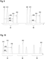
- Figure 9 shows a time diagram of the signal evaluation for the arrangement of the
- FIG 7 in the event that the beam guidance means of the optical sensors 101, 102 can be operated at the same speed.
- Figure 9 the signals received at the optical sensor 101 for measuring windows 51, 52 of two successive scans are shown.
- Figure 9 shows that the transmitted light pulse 311 of the optical sensor 101 is emitted at a time offset from the transmitted light pulse 321 of the optical sensor 102.
- the transmitted light pulse 311 of the optical sensor 101 is reflected back by the object 5 and hits the receiver 4 of the optical sensor 101 offset by a time difference 412 as a received light pulse 312.
- This time difference 412 corresponds to the light transit time of the transmitted light pulse 311 to the object 5 and back to the receiver 4 of the optical Sensor 101. This provides a correct distance value for the distance of the object 5 to the optical sensor 101.
- the transmitted light pulse 321 of the second optical sensor 102 is reflected from the object 5 to the optical sensor 101 and generates the received light pulse 313 there.
- the optical sensor 101 registers the time difference 422 between the transmitted light pulse 311 and the received light pulse 313 of the second optical sensor 102, which forms a stray light pulse .
- the beam guidance means of the optical sensors 101, 102 are operated at the same speed in this case, the signals during the first measuring window 51 are repeated exactly again in the second measuring window 52.
- the optical sensor 101 thus again registers the falsified time difference 422, i.e. the distance of the Object 5 in the optical sensor 101 is incorrectly determined.
- the adaptive correction unit of the optical sensor 101 detects the interference from the optical sensor 102 as glare events. Then measures are taken in the adaptive correction unit generated, through which future glare events are less likely to affect the optical sensor 101.
- the illustrated measuring windows 51, 52, 54 of the optical sensor 101 are shifted, which can be achieved, for example, by changing the speed of the beam guiding means.
- the following measurement windows 54 (in Figure 10 only one such measuring window 54 is shown) is shifted, so that the interference (received light pulse 313 or in the case of the arrangement according to Figure 8 Transmitted light pulses 321 irradiated directly from the optical sensor 102) lie outside this measuring window 54, or because the interference 313 occurs behind the received pulse 312 and does not distort its distance.
- FIG 11 shows an exemplary embodiment of an optical sensor 100 in the form of a light curtain.
- the light curtain has a transmitter unit 20 and a receiver unit 40, which are arranged at opposite edges of a monitoring area.
- a series arrangement of transmitters 3 is provided in the transmitter unit 20, the light beams 2 in the form of light pulses 2110 ( Figure 13 ) emit.
- a series arrangement of receivers 4 receiving light beams 2 is provided in the receiver unit 40.
- the light beams 2 from each transmitter 3 hit an assigned receiver 4.
- the transmitter-receiver pairs formed in this way form beam axes of the light curtain. Through optical synchronization, the beam axes are activated cyclically one after the other.
- At least one beam axis is interrupted by an object intervention in the monitoring area.
- the evaluation unit present in the receiver unit 40 generates a binary switching signal as an object detection signal, whose switching states indicate whether an object 5 is in the monitoring area or not.
- Figure 12 shows an arrangement of two adjacent optical sensors 101, 102, each designed as a light curtain.
- the first light curtain has a transmitter unit 21 and a receiver unit 41.
- the second light curtain has a transmitter unit 22 and a receiver unit 42.
- the beam angle ranges 410, 420 of the transmitter units 21, 22 of both light curtains are shown.
- the beam angle ranges 410, 420 overlap in an overlap area 400. Therefore, not only the light rays 2 of the transmitter unit 21 of this light curtain are irradiated into the receiver unit 41 of the light curtain, but also light rays 2 'of the transmitter unit 22 of the second light curtain as interference rays, as in Figure 12 illustrated.
- Figure 13 shows timing diagrams of the light pulses 2110 of the first light curtain and the light pulses 2210 of the second light curtain.
- the adaptive correction unit of the first light curtain registers these interferences, i.e. glare events, and shifts the transmission clock of the first light curtain (time window 2111 ') so that interference 2110 is avoided.
- the scanning windows on the receiving side can also be moved.
- Light pulses 2110 in the form of pulse groups can detect the interference radiation from the other light curtain in a light curtain.
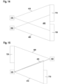
- Figure 14 shows a first arrangement of two optical sensors 101, 102 in the form of position sensors.
- the position sensors are used to detect marks on a position scale 710, 720, which can be in the form of a barcode tape. By detecting the marks, positioning of the position sensors relative to the position scale 710, 720 is possible.
- the position scale 710 is detected with the optical sensor 101, and the position scale 720 is detected with the optical sensor 102.
- the position sensors emit transmitted light in a beam angle range 410 or 420.
- the beam angle ranges 410, 420 overlap in an overlap range 400, whereby one position sensor can receive interference radiation from the other position sensor.
- the position sensors can be in the form of camera-based sensors or scanning systems.
- the position sensors are arranged next to each other and the position scales 710, 720 are also arranged next to each other.
- Figure 15 shows a variant of this arrangement such that both the position sensors and the position scales 710, 720 are arranged opposite one another.
- the beam angle ranges 410, 420 overlap in an overlap area 400, so that interference 2110 from one position sensor is possible in the other position sensor.
- Figure 16 shows a time diagram for the transmission operation of the two position sensors Figure 14 or Figure 15 .
- FIG 16 the illumination time intervals 4110, 4110' of the first position sensors and the illumination time intervals 4210, 4210' of the second position sensor are shown, in which the first position sensor illuminates the first detection area and the second position sensor illuminates the second detection area.
- the time ranges of the camera image or the signals registered at the receiver 4 of the scanning system are designated by 4130, 4130'.
- the detection cycle of the first position sensor is designated by 4140.
- the detection cycle of the second position sensor is designated by 4240.
- the lighting time intervals 4110, 4110' or 4210, 4210' or the detection cycles 4140, 4240 can be shifted in such a way that the probability of mutual influence on the position sensors is reduced.
Landscapes
- Physics & Mathematics (AREA)
- Engineering & Computer Science (AREA)
- General Physics & Mathematics (AREA)
- Electromagnetism (AREA)
- Computer Networks & Wireless Communication (AREA)
- Radar, Positioning & Navigation (AREA)
- Remote Sensing (AREA)
- Life Sciences & Earth Sciences (AREA)
- General Life Sciences & Earth Sciences (AREA)
- Geophysics (AREA)
- Geophysics And Detection Of Objects (AREA)
Priority Applications (1)
| Application Number | Priority Date | Filing Date | Title |
|---|---|---|---|
| EP22167297.5A EP4258022A1 (fr) | 2022-04-08 | 2022-04-08 | Capteur optique pour la détection d'objets dans une zone de surveillance |
Applications Claiming Priority (1)
| Application Number | Priority Date | Filing Date | Title |
|---|---|---|---|
| EP22167297.5A EP4258022A1 (fr) | 2022-04-08 | 2022-04-08 | Capteur optique pour la détection d'objets dans une zone de surveillance |
Publications (1)
| Publication Number | Publication Date |
|---|---|
| EP4258022A1 true EP4258022A1 (fr) | 2023-10-11 |
Family
ID=81386722
Family Applications (1)
| Application Number | Title | Priority Date | Filing Date |
|---|---|---|---|
| EP22167297.5A Pending EP4258022A1 (fr) | 2022-04-08 | 2022-04-08 | Capteur optique pour la détection d'objets dans une zone de surveillance |
Country Status (1)
| Country | Link |
|---|---|
| EP (1) | EP4258022A1 (fr) |
Citations (7)
| Publication number | Priority date | Publication date | Assignee | Title |
|---|---|---|---|---|
| DE10313709A1 (de) * | 2003-03-27 | 2004-10-21 | Leuze Lumiflex Gmbh + Co. Kg | Optischer Sensor |
| EP1972961B1 (fr) * | 2007-03-22 | 2012-02-01 | Sick Ag | Capteur optoélectronique et procédé de mesure de l'éloignement ou de la modification de l'éloignement |
| US20170242102A1 (en) * | 2016-02-18 | 2017-08-24 | Aeye, Inc. | Ladar System with Dichroic Photodetector for Tracking the Targeting of a Scanning Ladar Transmitter |
| DE102012101368B4 (de) * | 2012-02-21 | 2020-02-27 | Leuze Electronic Gmbh & Co. Kg | Lichtvorhang |
| US20200271764A1 (en) * | 2018-06-27 | 2020-08-27 | Hesai Photonics Technology Co., Ltd. | Adaptive coding for lidar systems |
| US20210302544A1 (en) * | 2020-03-27 | 2021-09-30 | Sick Ag | Acquisition of distance measurement data |
| EP3910439A1 (fr) * | 2020-05-12 | 2021-11-17 | Leuze electronic GmbH + Co. KG | Agencement de capteurs et son procédé de fonctionnement |
-
2022
- 2022-04-08 EP EP22167297.5A patent/EP4258022A1/fr active Pending
Patent Citations (7)
| Publication number | Priority date | Publication date | Assignee | Title |
|---|---|---|---|---|
| DE10313709A1 (de) * | 2003-03-27 | 2004-10-21 | Leuze Lumiflex Gmbh + Co. Kg | Optischer Sensor |
| EP1972961B1 (fr) * | 2007-03-22 | 2012-02-01 | Sick Ag | Capteur optoélectronique et procédé de mesure de l'éloignement ou de la modification de l'éloignement |
| DE102012101368B4 (de) * | 2012-02-21 | 2020-02-27 | Leuze Electronic Gmbh & Co. Kg | Lichtvorhang |
| US20170242102A1 (en) * | 2016-02-18 | 2017-08-24 | Aeye, Inc. | Ladar System with Dichroic Photodetector for Tracking the Targeting of a Scanning Ladar Transmitter |
| US20200271764A1 (en) * | 2018-06-27 | 2020-08-27 | Hesai Photonics Technology Co., Ltd. | Adaptive coding for lidar systems |
| US20210302544A1 (en) * | 2020-03-27 | 2021-09-30 | Sick Ag | Acquisition of distance measurement data |
| EP3910439A1 (fr) * | 2020-05-12 | 2021-11-17 | Leuze electronic GmbH + Co. KG | Agencement de capteurs et son procédé de fonctionnement |
Similar Documents
| Publication | Publication Date | Title |
|---|---|---|
| DE102012112987B3 (de) | Optoelektronischer Sensor und Verfahren zur Erfassung und Abstandsbestimmung von Objekten | |
| EP1548351B1 (fr) | Dispositif de surveillance d'une zone de couverture près d'une machine | |
| DE102010061382B4 (de) | Optoelektronischer Sensor und Verfahren zur Erfassung und Abstandsbestimmung von Objekten | |
| DE10312972B3 (de) | Optischer Sensor | |
| EP1300691A2 (fr) | Procédé de surveillance et capteur opto-électronique | |
| EP3575666B1 (fr) | Dispositif de sécurisation d'une zone à risque d'une installation | |
| EP4299970A1 (fr) | Dispositif de surveillance | |
| EP4325257A1 (fr) | Capteur optique | |
| EP2453260B1 (fr) | Capteur de surveillance doté d'un contrôle automatique | |
| EP3287809A1 (fr) | Procédé de fonctionnement d'un dispositif de baleyage et dispositif de baleyage | |
| EP3220164A1 (fr) | Procède de fonctionnement d'un capteur ecartométrique de surveillance et capteur ecartométrique de surveillance | |
| EP4258022A1 (fr) | Capteur optique pour la détection d'objets dans une zone de surveillance | |
| DE102004031024C5 (de) | Optischer Sensor | |
| DE10350927C5 (de) | Lichtgitter | |
| EP1798577B1 (fr) | Dispositif électro-optique et méthode d'operation d'un tel dispositif | |
| EP3614182B1 (fr) | Système de barrière lumineuse | |
| EP2306145B1 (fr) | Capteur optique | |
| DE202012105044U1 (de) | Optoelektronischer Sensor zur Erfassung und Abstandsbestimmung von Objekten | |
| EP4435478A1 (fr) | Capteur optique et procédé de fonctionnement d'un capteur optique | |
| EP1451614B1 (fr) | Procede de correction de lumiere parasite dans un ensemble capteur optique | |
| DE10313709B4 (de) | Optischer Sensor | |
| DE102011014195B4 (de) | Optischer Sensor | |
| DE102008009578A1 (de) | Verfahren zur Erfassung von Objekten mittels einer Sensoranordnung | |
| EP3540380B1 (fr) | Dispositif de surveillance pour une installation | |
| EP4098927B1 (fr) | Agencement de capteurs et son procédé de fonctionnement |
Legal Events
| Date | Code | Title | Description |
|---|---|---|---|
| PUAI | Public reference made under article 153(3) epc to a published international application that has entered the european phase |
Free format text: ORIGINAL CODE: 0009012 |
|
| STAA | Information on the status of an ep patent application or granted ep patent |
Free format text: STATUS: REQUEST FOR EXAMINATION WAS MADE |
|
| 17P | Request for examination filed |
Effective date: 20221018 |
|
| AK | Designated contracting states |
Kind code of ref document: A1 Designated state(s): AL AT BE BG CH CY CZ DE DK EE ES FI FR GB GR HR HU IE IS IT LI LT LU LV MC MK MT NL NO PL PT RO RS SE SI SK SM TR |
|
| P01 | Opt-out of the competence of the unified patent court (upc) registered |
Free format text: CASE NUMBER: UPC_APP_3396_4258022/2025 Effective date: 20250814 |
|
| STAA | Information on the status of an ep patent application or granted ep patent |
Free format text: STATUS: EXAMINATION IS IN PROGRESS |
|
| 17Q | First examination report despatched |
Effective date: 20260226 |