EP4259904B1 - Procédés de formation ou de réparation de pièce comportant une section en porte-à-faux, et pièce de turbomachine associée - Google Patents
Procédés de formation ou de réparation de pièce comportant une section en porte-à-faux, et pièce de turbomachine associée Download PDFInfo
- Publication number
- EP4259904B1 EP4259904B1 EP20830453.5A EP20830453A EP4259904B1 EP 4259904 B1 EP4259904 B1 EP 4259904B1 EP 20830453 A EP20830453 A EP 20830453A EP 4259904 B1 EP4259904 B1 EP 4259904B1
- Authority
- EP
- European Patent Office
- Prior art keywords
- material layers
- section
- overhung
- turbomachine
- layers
- Prior art date
- Legal status (The legal status is an assumption and is not a legal conclusion. Google has not performed a legal analysis and makes no representation as to the accuracy of the status listed.)
- Active
Links
Images




Classifications
-
- F—MECHANICAL ENGINEERING; LIGHTING; HEATING; WEAPONS; BLASTING
- F01—MACHINES OR ENGINES IN GENERAL; ENGINE PLANTS IN GENERAL; STEAM ENGINES
- F01D—NON-POSITIVE DISPLACEMENT MACHINES OR ENGINES, e.g. STEAM TURBINES
- F01D5/00—Blades; Blade-carrying members; Heating, heat-insulating, cooling or antivibration means on the blades or the members
- F01D5/005—Repairing methods or devices
-
- B—PERFORMING OPERATIONS; TRANSPORTING
- B23—MACHINE TOOLS; METAL-WORKING NOT OTHERWISE PROVIDED FOR
- B23P—METAL-WORKING NOT OTHERWISE PROVIDED FOR; COMBINED OPERATIONS; UNIVERSAL MACHINE TOOLS
- B23P6/00—Restoring or reconditioning objects
- B23P6/002—Repairing turbine components, e.g. moving or stationary blades, rotors
- B23P6/007—Repairing turbine components, e.g. moving or stationary blades, rotors using only additive methods, e.g. build-up welding
-
- F—MECHANICAL ENGINEERING; LIGHTING; HEATING; WEAPONS; BLASTING
- F01—MACHINES OR ENGINES IN GENERAL; ENGINE PLANTS IN GENERAL; STEAM ENGINES
- F01D—NON-POSITIVE DISPLACEMENT MACHINES OR ENGINES, e.g. STEAM TURBINES
- F01D5/00—Blades; Blade-carrying members; Heating, heat-insulating, cooling or antivibration means on the blades or the members
- F01D5/12—Blades
- F01D5/14—Form or construction
- F01D5/20—Specially-shaped blade tips to seal space between tips and stator
-
- F—MECHANICAL ENGINEERING; LIGHTING; HEATING; WEAPONS; BLASTING
- F01—MACHINES OR ENGINES IN GENERAL; ENGINE PLANTS IN GENERAL; STEAM ENGINES
- F01D—NON-POSITIVE DISPLACEMENT MACHINES OR ENGINES, e.g. STEAM TURBINES
- F01D5/00—Blades; Blade-carrying members; Heating, heat-insulating, cooling or antivibration means on the blades or the members
- F01D5/12—Blades
- F01D5/22—Blade-to-blade connections, e.g. for damping vibrations
- F01D5/225—Blade-to-blade connections, e.g. for damping vibrations by shrouding
-
- F—MECHANICAL ENGINEERING; LIGHTING; HEATING; WEAPONS; BLASTING
- F05—INDEXING SCHEMES RELATING TO ENGINES OR PUMPS IN VARIOUS SUBCLASSES OF CLASSES F01-F04
- F05D—INDEXING SCHEME FOR ASPECTS RELATING TO NON-POSITIVE-DISPLACEMENT MACHINES OR ENGINES, GAS-TURBINES OR JET-PROPULSION PLANTS
- F05D2230/00—Manufacture
- F05D2230/20—Manufacture essentially without removing material
- F05D2230/23—Manufacture essentially without removing material by permanently joining parts together
- F05D2230/232—Manufacture essentially without removing material by permanently joining parts together by welding
-
- F—MECHANICAL ENGINEERING; LIGHTING; HEATING; WEAPONS; BLASTING
- F05—INDEXING SCHEMES RELATING TO ENGINES OR PUMPS IN VARIOUS SUBCLASSES OF CLASSES F01-F04
- F05D—INDEXING SCHEME FOR ASPECTS RELATING TO NON-POSITIVE-DISPLACEMENT MACHINES OR ENGINES, GAS-TURBINES OR JET-PROPULSION PLANTS
- F05D2230/00—Manufacture
- F05D2230/80—Repairing, retrofitting or upgrading methods
-
- F—MECHANICAL ENGINEERING; LIGHTING; HEATING; WEAPONS; BLASTING
- F05—INDEXING SCHEMES RELATING TO ENGINES OR PUMPS IN VARIOUS SUBCLASSES OF CLASSES F01-F04
- F05D—INDEXING SCHEME FOR ASPECTS RELATING TO NON-POSITIVE-DISPLACEMENT MACHINES OR ENGINES, GAS-TURBINES OR JET-PROPULSION PLANTS
- F05D2240/00—Components
- F05D2240/20—Rotors
- F05D2240/30—Characteristics of rotor blades, i.e. of any element transforming dynamic fluid energy to or from rotational energy and being attached to a rotor
- F05D2240/307—Characteristics of rotor blades, i.e. of any element transforming dynamic fluid energy to or from rotational energy and being attached to a rotor related to the tip of a rotor blade
-
- F—MECHANICAL ENGINEERING; LIGHTING; HEATING; WEAPONS; BLASTING
- F05—INDEXING SCHEMES RELATING TO ENGINES OR PUMPS IN VARIOUS SUBCLASSES OF CLASSES F01-F04
- F05D—INDEXING SCHEME FOR ASPECTS RELATING TO NON-POSITIVE-DISPLACEMENT MACHINES OR ENGINES, GAS-TURBINES OR JET-PROPULSION PLANTS
- F05D2300/00—Materials; Properties thereof
- F05D2300/10—Metals, alloys or intermetallic compounds
Definitions
- the disclosure relates generally to part manufacturing and repair, and more particularly, to methods of forming or repairing a turbomachine part, such as a turbomachine blade, with an overhung section.
- Flared tip turbomachine blades include an airfoil having a pressure side and a suction side coupled along leading and trailing edges.
- the flared tip is coupled to a radially outer end of the airfoil, and may extend circumferentially beyond the pressure side and/or suction side of the airfoil, i.e., using an axis of the turbomachine as a reference.
- WO2015/150019A1 discloses a repair method of a turbomachine part by adding layers of a superalloy.
- WO01/51772A1 discloses a method of repairing a tip portion of a blade by welding.
- An aspect of the disclosure provides a turbomachine part as set forth in claim 1.
- Another aspect of the disclosure relates to a method as set forth in claim 10.
- forward and aft refer to directions relative to the orientation of the gas turbine and, more specifically, the relative positioning of the compressor and turbine sections of the engine.
- forward refers to the compressor end while “aft” refers to the turbine end.
- each of these terms may be used to indicate direction of movement or relative position along the central axis of the engine. As stated above, these terms may be used to describe attributes of the gas turbine or one of its primary subsystems, as well as for components or subcomponents positioned therewithin.
- a component such as a turbomachine blade
- a forward face it may be understood as referring to a face that faces toward the forward direction as defined by the orientation of the gas turbine (i.e., the compressor being designated as the forward end and turbine being designated as the aft end).
- the forward and aft directions may be defined relative to a forward end of the turbine, at where a working fluid enters the turbine, and an aft end of the turbine, at where the working fluid exits the turbine.
- downstream and upstream are used herein to indicate position within a specified conduit or flowpath relative to the direction of flow (hereinafter “flow direction”) moving through it.
- flow direction refers to the direction in which a fluid is flowing through the specified conduit
- upstream refers to the direction opposite to that.
- the term “radial” refers to movement or position perpendicular to an axis. Related to this, it may be required to describe relative distance from the central axis. In such cases, for example, if a first component resides closer to the central axis than a second component, the first component will be described as being either “radially inward” or “inboard” of the second component. If, on the other hand, the first component resides further from the central axis, the first component will be described as being either “radially outward” or “outboard” of the second component.
- the term “axial” refers to movement or position parallel to an axis
- the term “circumferential” refers to movement or position around an axis.
- turbomachine blade is a reference to the rotating blades of either the compressor or the turbine, and so may include both compressor rotor blades and turbine rotor blades, and may also be a reference to stationary blades of either the compressor or the turbine and so may include both compressor stator blades and turbine stator blades.
- blades may be used to generally refer to either type of blade.
- turbine blade or “blade” is inclusive to all type of turbine engine blades, including compressor rotor blades, compressor stator blades, turbine rotor blades, turbine stator blades, and the like.
- FIGS. 1-3 illustrate an illustrative gas turbine in accordance with the present disclosure or within which turbomachine parts of the present disclosure may be used.
- FIG. 1 is a schematic representation of a gas turbine 10.
- gas turbines operate by extracting energy from a pressurized flow of hot gas produced by the combustion of a fuel in a stream of compressed air.
- gas turbine 10 may be configured with an axial compressor 12 that is mechanically coupled by a common shaft or rotor to a downstream turbine section or turbine 14, and a combustor 16 positioned between compressor 12 and turbine 14.
- gas turbine 10 may be formed about a common central axis 18.
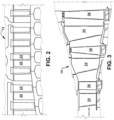
- FIG. 2 illustrates a view of an illustrative multi-staged axial compressor 12 that may be used in gas turbine 10 of FIG. 1 .
- compressor 12 may have a plurality of stages, each of which include a row of compressor rotor blades 20 and a row of compressor stator blades 22.
- a first stage may include a row of compressor rotor blades 20, which rotate about a central shaft, followed by a row of compressor stator blades 22, which remain stationary during operation.
- FIG. 3 illustrates a partial view of an illustrative turbine section or turbine 14 that may be used in gas turbine 10 of FIG. 1 .
- Turbine 14 also may include a plurality of stages. Three illustrative stages are shown, but more or less may be present.
- Each stage may include a plurality of turbine nozzles or stator blades 24, which remain stationary during operation, followed by a plurality of turbine buckets or rotor blades 26, which rotate about the shaft during operation.
- Turbine stator blades 24 generally are circumferentially spaced one from the other and fixed about the axis of rotation to an outer casing.
- Turbine rotor blades 26 may be mounted on a turbine wheel or rotor disc (not shown) for rotation about a central axis. It will be appreciated that turbine stator blades 24 and turbine rotor blades 26 lie in the hot gas path or working fluid flowpath through turbine 14. The direction of flow of the combustion gases or working fluid within the working fluid flowpath is indicated by the arrow.
- the rotation of compressor rotor blades 20 within axial compressor 12 may compress a flow of air.
- energy may be released when the compressed air is mixed with a fuel and ignited.
- the resulting flow of hot gases or working fluid from combustor 16 is then directed over turbine rotor blades 26, which induces the rotation of turbine rotor blades 26 about the shaft.
- the energy of the flow of working fluid is transformed into the mechanical energy of the rotating blades and, given the connection between the rotor blades and the shaft, the rotating shaft.
- the mechanical energy of the shaft may then be used to drive the rotation of compressor rotor blades 20, such that the necessary supply of compressed air is produced, and/or, for example, a generator to produce electricity.
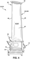
- FIG. 4 provides a perspective view of an illustrative part 28 having an overhung section 30.
- part 28 is illustrated as a flared tip turbomachine blade 25, and more particularly, a turbine rotor blade 26. It is noted that the teachings of the disclosure are also applicable to any part 28 with overhung section 30 other than a turbomachine blade 25, as described herein, such as any other hot gas path (HGP) part of gas turbine 10. The teachings of the disclosure are also applicable to other industrial parts having an overhung section.
- HGP hot gas path
- Turbomachine blade 25 may include a root 31 that is configured for attaching to a rotor disc. Root 31, for example, may include a dovetail 32 configured for mounting in a corresponding dovetail slot in the perimeter of a rotor disc. Root 31 may further include a shank 34 that extends between dovetail 32 and a platform 36. Platform 36, as shown, generally forms the junction between root 31 and an airfoil 40, with the airfoil being the active component of turbine rotor blade 26 that intercepts the flow of working fluid through turbine 14 and induces the desired rotation. Platform 36 may define the inboard end of airfoil 40. Platform 36 also may define a section of the inboard boundary of the working fluid flowpath through turbine 14.
- Airfoil 40 of the turbomachine blade typically includes a concave pressure face 42 and a circumferentially or laterally opposite convex suction face 44.
- Pressure face 42 and suction face 44 may extend axially between opposite leading and trailing edges 46, 48, respectively, and, in the radial direction, between an inboard end, which may be defined at the junction with platform 36, and an outboard tip, which may include a flared tip rail.
- Airfoil 40 may include a curved or contoured shape that is designed for promoting desired aerodynamic performance.
- turbomachine blade 25 and components thereof may be described according to orientation characteristics of turbine 14. It should be appreciated that, in such cases, turbomachine blade 25 is assumed to be properly installed within turbine 14. Such orientation characteristics may include radial, axial, and circumferential directions defined relative to central axis 18 ( FIG. 1 ) of turbine 14. Forward and aft directions may be defined relative to a forward end of turbine 14, at where the working fluid enters turbine 14 from combustor 16, and an aft end of turbine 14, at where the working fluid exits turbine 14. A rotation direction may be defined relative to an expected direction of rotation of turbomachine blade 25 about central axis 18 ( FIG. 1 ) of turbine 14 during operation.
- the disclosure provides methods of forming or repairing part 28 with an overhung section 30, e.g., a flared tip of turbomachine blade 25.
- the method may include removing a portion, and adding a section to the part.
- the method may add a section to a portion of part 28 already formed.
- the section being added or formed includes the overhung section.
- the adding includes sequentially layering one or more pluralities of material layers on the part. When complete, the plurality of material layers approximates dimensions of the section including the overhung section.
- the sequential layering may include, for example, laser welding, cold metal transfer (CMT), tungsten inert gas (TIG) welding, laser sintering, direct metal laser melting (DMLM), net shape methods, near net shape methods, etc., and may be carried out in a number of ways that create varied layers within the section.
- the method and resulting part formed thereby may be formed by net shape methods that minimize or eliminate post build processing or finishing.
- the method may include machining the at least one plurality of material layers to form the section including the overhung section.
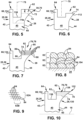
- FIG. 5 shows an enlarged, cross-sectional view of a used part 28 having a body 60 having a first side 62 and an opposing, second side 64, according to embodiments of the disclosure.
- Body 60 may also have a longitudinal axis 75.
- Longitudinal axis may be any axis of reference of body 60, e.g., through a length thereof.
- the longitudinal axis may be a radial axis as the airfoil is positioned in gas turbine 10 ( FIG. 1 ).
- Overhung section 30 extends in an overhung manner from, for example, first side 62 of body 60. Overhung section 30 lacks vertical structural support in a portion thereof.
- overhung section 30 is opposite an opposing member 66 on second side 64 of body 60, and has more mass than opposing member 66.
- part 28 includes turbomachine blade 25 including a flared tip rail 70 that overhangs, for example, suction face 44 of the blade on first side 62.
- flared tip rail 70 is an example of an overhung section 30 ( FIG. 4 ) of a part 28.
- Body 60 includes airfoil 40, and flared tip rail 70 is opposite an opposing member 66 in the form of a radially extending tip rail 134 extending from an end of airfoil 40. Flared tip rail 70 extends circumferentially relative to an axis 18 ( FIG. 1 ) of gas turbine 10.
- overhung section 30 may be opposite another overhung section, e.g., flared tip rail 70, that may or may not have different mass, and may extend around the periphery of airfoil 40 - see e.g., FIGS. 23 and 24 .
- a damaged overhung portion may include overhung flared tip rail 70, i.e., an overhung flared tip rail lacking structural support.
- Portion 72 may include any structure that is desired to be removed, and may include a portion with no damage or a portion with a variety of damage such as but not limited to worn surfaces, cracks, openings, roughness, etc. In this situation, as shown in FIG. 6 , portion 72 may be removed from part 28 to create a surface 74 on the part, e.g., on turbomachine blade 25. Portion 72 may also be defined by surface/line 74a, where the portion removed is deeper and extends to a non-flared section of suction face 44.
- Portion 72 may be removed using any now known or later developed technique including but not limited to: electric discharge machining (EDM), mechanical cutting/grinding, laser cutting, etc. As shown in FIG. 6 , while some remnants of flared tip rail 70 may or may not remain, portion 72 is removed so as to form a surface 74 upon which the removed section can be reformed. Surface 74 may be flat, curved or have a three-dimensional shape or profile. As also shown in FIG. 6 , in one embodiment, the angle of surface 74 can be a substantially horizontal plane, i.e., with body in a vertical position - longitudinal axis 75 vertical.
- EDM electric discharge machining
- FIG. 6 the angle of surface 74 can be a substantially horizontal plane, i.e., with body in a vertical position - longitudinal axis 75 vertical.
- surface 74 may also be formed at a non-horizontal angle, and the part rotated as required to allow formation of new layers.
- at most half of flared tip rail 70 is removed, e.g., based on at most half of portion 72 being removed.
- more than half of flared tip rail 70 is removed, e.g., based on more than half of portion 72 being removed.
- Embodiments of the disclosure may also include initial manufacture of flared tip rail 70.
- the starting structure as shown in FIG. 6 , may be manufactured using any appropriate technique for the material and structure being built. Non-limiting examples may include casting and additive manufacture.
- surface 74 upon which an overhung section is to be built is generated.
- FIG. 7 shows a cross-sectional view of adding a section 76 to part 28, where section 76 includes a new overhung section 78.
- the adding includes sequentially layering a plurality 80 of material layers 82 on part 28, i.e., on surface 74. Collectively, when complete, the plurality of material layers 82 approximates dimensions of the section including new overhung section 78. That is, the added section approximates dimensions of the desired new overhung section 78 being added, or portion 72 being replaced. As used herein, "approximate dimensions" generally indicates the new overhung section 78 can be formed by material removal with machining, and little or no additional material add.
- the adding of material layers 82 can be provided in a number of ways.
- material layers 82 may be formed using laser welding, laser cladding, cold metal transfer (CMT), tungsten inert gas (TIG) welding, additive manufacturing, metal sintering, direct metal laser melting (DMLM), etc.
- sequential layering of plurality 80 of material layers 82 on part 28 includes forming a series of weld beads 84 to form each layer 82. Any number of weld beads 84 may be used to form a single layer.
- the layers may be formed using the welding in any pattern, e.g., starting at a center or periphery and forming them in a continuous spiral weld bead, or forming individual linear weld beads side-by-side that extend from side to side of surface 74, or a combination thereof.
- Surface 74 may be positioned in a substantially horizontal position (e.g., no more than +/- 3° from horizontal) during the sequential layering to foster even layering of material, and then portion 72 can be replaced by sequentially layering at least one plurality 80 of material layers 82 on surface 74.
- first ends 86 of the single plurality of material layers 82 may not be precisely aligned as illustrated, and may have uneven edges relative to surface 88 of part 28. These uneven edges may be later machined to be aligned with surface 88 of part 28.
- FIG. 9 shows a schematic plan view of weld beads 84 of layers 82.
- weld beads 84 of different layers 82A may be angled relative to weld beads 84 of other layers 82B.
- series of weld beads 84 for at least one first material layer 82A of plurality 80 of material layers 82 may be formed at a non-parallel angle to the series of weld beads 84 for at least one second material layer 82B of the same plurality 80 of layers. Any angle may be employed to foster strength in the new section 76 ( FIG. 10 ).
- the sequential layering may be carried out in a manner to control a local temperature of the structure to prevent thermal cracking.
- a user could jump from place-to-place on a build surface 74 to allow cooling in one area while working in another area, and ensuring a new weld bead is applied in a location that has cooled prior to application of the new weld bead.
- FIG. 10 shows part 28 after machining plurality 80 of material layers 82 to form new section 76 including new overhung section 78.
- overhung section 78 may match a shape and dimensions of portion 72 ( FIG. 5 ). Alternatively, it may have a different shape and dimensions to provide improved performance and/or longevity.
- Machining may include any manner of material removal allowing blending of surfaces, resulting in the desired shape and dimension for new section 76. Non-limiting and non-comprehensive examples of machining may include: milling, grinding, cutting, polishing, etc.
- body 60 may include an airfoil 40 of turbomachine blade 25.
- overhung section 78 includes flared tip rail 70 extending from one of first side 62 (shown) and second side 64 of the airfoil 40.
- turbomachine blade 25 includes flared tip rail 70 extending from airfoil 40, with radially-facing outer surface 138 of overhung section 78 being parallel to axis 18 of the turbomachine.
- surface 74 is formed so as to be parallel to a radially-facing outer surface 92 of new section 76, e.g., perhaps extending parallel relative to axis 18 ( FIG. 1 ) of gas turbine 10 ( FIG. 1 ).
- surface 74 extends perpendicular to a longitudinal axis 75 of the part, or in terms of a turbomachine blade, a radial axis 75 of body 60 of airfoil 40. Consequently, part 28 includes at least a portion of overhung section 78 that includes a plurality 80 of material layers 82, where each material layer 82 extends at a perpendicular angle relative to a longitudinal axis 75 of body 60.
- the portion of overhung section 78 may include at most half of overhung section 78 extending from a floor surface 136 to a radially-facing outer surface (when blade mounted) of overhung section 78, or more than half of overhung section 78.
- part 28 may be rotated so that surface 74 is inclined from horizontal.
- the angle of rotation 01 may be about 15° to about 60°, so that longitudinal axis 75 of part 28 is at angle of rotation 01 from vertical.
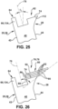
- FIG. 26 shows a cross-sectional view of adding new section 76 to part 28, where new section 76 includes a new overhung section 78.
- the adding includes sequentially layering a plurality 80 of inclined material layers 82 on part 28, i.e., on inclined surface 74.
- plurality 80 of material layers 82 approximates dimensions of new section 76 including overhung section 78 with a greater overhang angle than would be obtainable with a horizontal surface build as shown in FIG. 7 . That is, the added section 76 approximates dimensions of the desired new overhung section 78 being added, or damaged section 72 ( FIG. 5 ) being replaced, or if desired, with a greater overhang angle.
- an overhang angle ⁇ 2 may be about 50° to about 65°, or about 55° to about 60°.
- the overhang angle ⁇ 2 is measured between the longitudinal axis 75 of the part and a line intersecting the bottom corners (or edge) of the overhanging material layers 82, as shown in FIG. 26 .
- the inclined build reduces the perceived overhang of each layer, so that greater amounts of overhang may be successfully obtained.
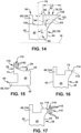
- removing portion 72 of part 28 may include creating a surface 94 that is not perpendicular to longitudinal axis 75 of body 60, i.e., a radial axis 75 of body 60 of airfoil 40. Rather, surface 94 may be at an acute angle ⁇ relative to longitudinal axis 75 of body 60, i.e., a radial axis 75 of airfoil 40. To be clear, an acute angle is between 0° and 90°. Surface 94 may also be at an acute angle ⁇ relative to an axis 18 (added in phantom in FIG. 11 ) of gas turbine 10.
- surface 94 will be at an angle that is neither perpendicular nor parallel to a target radially-facing outer planar surface 96 ( FIG. 14 ) of new overhung section 78 of the final product, i.e., a new flared tip rail.
- surface 94 may be rotated so as to be substantially horizontal (+/-3°) prior to sequentially layering plurality 80 of material layers 82 thereon.
- part 28 may be rotated to position surface 94 at angle ⁇ other than horizontal and vertical prior to sequentially layering plurality 80 of material layers 82.
- Part 28 may alternatively be rotated to the FIG. 13B position after a certain number of material layers 82 are sequentially layered.
- Angle ⁇ may be any angle that allows for the desired stepping of plurality 80 of material layers 82, i.e., that is not substantially horizontal as defined herein.
- angle ⁇ may be such that ends 98 of layers 82 step outwardly in a manner that allows later machining of the ends to be aligned with surface 88, and such that ends 100 of layers 82 step outwardly in a manner that forms new overhung section 78 of part 28.
- Angle ⁇ may allow formation of overhung section 78 with an extent that could not be created if surface 94 was horizontal.
- an outward length L2 ( FIG. 14 ) of new overhung section 78 could be greater than an initial outward length L1 ( FIG. 11 ) of original overhung section 30, or an angle ⁇ 2 of new overhang section 78 relative to radial axis 75 of body 60 may be greater than an initial angle ⁇ 1 ( FIG.
- Angle ⁇ may be any angle that allows for the sequential layering without allowing undesired forming of the layers, e.g., in the form of dripping, slumping or breaking.
- FIGS. 13A-B also show sequentially layering plurality 80 of layers 82 on surface 94.
- each end 98, 100 of layers 82 may be stair-stepped. That is, as shown in FIGS. 13A-B , the sequential layering of plurality 80 of material layers 82 may include forming a first end 98 of the plurality of material layers in a stair-stepped manner from a first side of the surface 94, and a second end 100 of plurality 80 of material layers 82 in a stair-stepped manner from a second side of the surface 94.
- One of the first end and the second ends (100 as shown) approximates dimensions of section 76 including overhung section 78, as described herein.
- Ends 98 may be stair-stepped so as to be aligned with surface 88 of part 28, when finished, and as noted, ends 100 may be stair-stepped so as to form new overhung section 78 of part 28, e.g., a new flared tip rail for turbomachine blade 25.
- layers 82 in new overhung section 78 of the finished product extend at acute angle ⁇ relative to axis 18 (shown schematically in phantom) of gas turbine 10 ( FIG. 1 ), at acute angle ⁇ relative to target outer surface 96 ( FIG.
- target outer surface 96 when complete, is at angle ⁇ relative to plurality 80 of material layers 82 and surface 94 upon which the layers are built. It is to be understood that while target surface 96 is shown as planar, it may also not be a planar surface;for example, surface 96 could be curved or have a three-dimensional profile.
- FIG. 14 shows machining plurality 80 of material layers 82 to form overhung section 78 and target outer planar surface 138.
- Target outer (planar) surface 96 is at angle ⁇ relative to plurality 80 of material layers 82.
- Turbomachine part 28, shown in FIG. 14 includes body 60 having a first side 62, a second side 64 which may be opposed first side 62, and a longitudinal axis 75.
- Overhung section 76 extends in an overhung manner from at least one of first side 62 (shown) and second side 64 of body 60.
- FIG. 23 shows overhung sections extending from both sides. As noted in FIG.
- overhung section 78 includes a plurality 80 of material layers 82, where each material layer 82 extends at an acute angle ⁇ relative to longitudinal axis 75 of body 60.
- a radially extending tip rail 134 may extend from the airfoil 40 (from the other side of body 60), and radially-facing outer surface 138 of the overhung section 78 may be parallel to axis 18 of the turbomachine, when in an operative position.
- more than one plurality of material layers 82 may be used to form new section 76 including new overhung section 78.
- a section 76 may be added to part 28, including overhung section 78 by sequential layering more than one plurality of material layers.
- the method may include sequentially layering a first plurality of material layers on the part extending in a first direction, and sequentially layering a second plurality of material layers on the part extending in a second direction different than the first direction, e.g., two pluralities of layers built on perpendicular surfaces formed on the part.
- the second plurality of material layers generally meets with the first plurality of material layers, i.e., to form new section 76.
- each plurality of layers can vary in material, e.g., material layers may alternate material within a given plurality of layers.
- the material within each plurality of layers may be the same, but the two pluralities of layers may use different material.
- Either or both pluralities of material layers 82 may use the same or different material than body 60.
- any portion 72 of part 28 may be removed, creating surface 74. Otherwise, formation of new section 76 may be from a part initially formed, as shown in FIG. 6 .
- adding section 76 to part 28 including overhung section 78 may include sequential layering a first plurality 110 of material layers 82 on part 28 extending in a first direction, e.g., generally horizontal as shown but perhaps with some angle departing from horizontal.
- first plurality 110 of layers 82 may be sequentially formed horizontally on part 28 in a manner that consumes a portion 112 ( FIG. 6 ) of flared tip rail 70.
- FIG. 1 first plurality 110 of layers 82
- any material desired such as portion 112 (shown in phantom) of flared tip rail 70 ( FIG. 6 ), may be removed to form another surface 114. That is, another portion 112 of part 28 is removed to create another surface 114.
- layers 82 may be sequentially formed horizontally on part 28 on surface 114, i.e., not consuming any other material.
- sequential layering of first plurality 110 of material layers 82 is on surface 114 and forms an extension 116 of surface 114. Ends 118 of layers 82 are ideally aligned with surface 74 when formed, but where they are not aligned, they may be machined to be aligned with surface 74.
- first plurality 110 of material layers 82 creates extension 116 of surface 74.
- alternative embodiments may form the extension with a stair-stepped end - see e.g., FIG. 18C and 19 .
- FIG. 17 shows rotating part 28 such that surface 74 is at a different angle, e.g., substantially horizontal
- FIG. 18A shows sequentially layering a second plurality 120 of material layers 82 on part 28 extending in a second, different direction, e.g., perpendicular to first plurality 110 of material layers 82.
- sequential layering of first plurality 110 of material layers 82 creates extension 116 of surface 74
- sequential layering of a second plurality 120 of material layers 82 is on first surface 74 and extension 116 of first surface 74.
- Second plurality 120 of material layers 82 meet with first plurality 110 of material layers 82, i.e., generally they come together and mate or generally mate together.
- FIGS. 18A-18E show various embodiments that result in first plurality 110 of material layers 82 and second plurality 120 of material layers 82 collectively approximating the dimensions of new section 76 including new overhung section 78, and being non-coplanar relative to one another.
- the second plurality 120 of material layers 82 can extend in a variety of non-coplanar directions (i.e., not in the same plane) relative to the first direction of first plurality 110 of material layers 82.
- FIGS. 17 and 18A show an embodiment in which the eventual horizontal second plurality 120 of material layers 82 extends over vertical first plurality 110 of material layers 82, i.e., with angle ⁇ between surfaces 74, 114 substantially perpendicular (90° +/-2°).
- FIG. 18B shows an alternative embodiment in which plurality 110, 120 of material layers are reversed in position. That is, second plurality 120 of material layers 82 is formed first on surface 74 and provides extension 116. Then, part 28 is rotated to have surface 114 and extension 116 available to be built on, and first plurality 110 of material layers 82 is formed. First plurality 110 of material layers 182 ends up extending adjacent ends of second plurality 120 of material layers 82 that form extension 116.
- FIG. 18C shows another alternative embodiment of the part after repeating the sequentially layering of each plurality.
- less than all material layers 82 of first and second pluralities 110, 120 of material layers 82 are formed on the part between rotations of the part.
- some number of layers, e.g., 1-4, less than all layers of first or second plurality 110, 120 of material layers 82 are built on one surface 74, 114; the part is then rotated, and another number of layers, e.g., 1-4, less than all of the other plurality 110, 120 of material layers 82, is built on the opposing surface 74, 114.
- This approach creates a stair-stepped mating or generally stair-stepped mating of groups of layers 82 within each plurality 110, 120. This process may be advantageous for reducing thermal stress, and to address other mechanical issues.
- FIGS. 18D-E show other alternative embodiments of the part in which surfaces 74 and 114 are formed in non-coplanar directions and have a non-perpendicular (90°) angle ⁇ .
- the positioning of surfaces 74 or 114 during layering of respective pluralities 110, 120 of material layers 82 can be at any position necessary to ensure the desired joining of layers and accommodate hardware welding constraints.
- FIG. 18D shows surfaces 74, 114 at an obtuse angle ⁇ (90° ⁇ 180°)
- FIG. 18E shows surfaces 74, 114 at an angle ⁇ that is greater than 180°.
- FIGS. 19-21 show an alternative embodiment that is substantially similar to that described relative to FIGS. 15-18E , except sequential layering of the first and second plurality 110, 120 of material layers 82 each create stair-stepped ends that generally meet with one another.
- the first sequential layering may consume portion 112 of the part, or another surface 114 can be created by removing portion 112 of the part and the layering completed on the surface.
- any portion 72 of part 28 may be removed to create surface 74, 114.
- FIG. 19 shows sequential layering of first plurality 110 of material layers 82 to create a stair-stepped extension 122 of surface 114.
- FIG. 20 shows any necessary rotating of the part
- FIG. 21 shows sequential layering of second plurality 120 of material layers 82 on surface 74 and stair-stepped extension 122 ( FIG. 20 ) of surface 74. More particularly, sequential layering of second plurality 120 of material layers 82 on surface 74 is carried out to generally mate material layers 82 thereof with stair-stepped extension 122 of surface 74 formed by first plurality 110 of material layers 82, creating an interlocked bond.
- FIG. 20 shows any necessary rotating of the part
- FIG. 21 shows sequential layering of second plurality 120 of material layers 82 on surface 74 and stair-stepped extension 122 ( FIG. 20 ) of surface 74. More particularly, sequential layering of second plurality 120 of material layers 82 on surface 74 is carried out to generally mate material layers 82 thereof with stair-stepped extension 122 of surface 74 formed by first plurality 110 of
- the two pluralities 110, 120 of material layers 82 may have mating stair-stepped ends, or have generally mating stair-stepped ends with perhaps some voids 83 therebetween at some locations. That is, ends of first plurality 110 of material layers 82 meet ends of second plurality 120 of material layers 82 in a stair-stepped fashion, perhaps with some voids 83 therein. While surfaces 74, 114 are shown as perpendicular to one another in FIGS. 19-22 , any of the angles ⁇ described relative to FIGS. 18A-E may be employed with the stair-stepped layers.
- FIG. 22 shows part 28 after machining pluralities 110, 120 of material layers 82 to form section 76 including new overhung section 78.
- This process can follow any of the described processes of sequentially layering more than one plurality of material layers.
- This machining process may be as described relative to FIG. 10 . While the machining is shown carried out from the FIG. 21 embodiment, it will be recognized that similar machining may be performed on the FIGS. 18A-E embodiments.
- FIG. 22 illustrates a turbomachine part 28 including body 60 having first side 62 and second side 64.
- Overhung section 78 extends in an overhung manner from at least one of first side 62 and second side 64 (shown) of body 60.
- At least a portion of overhung section 78 includes a first plurality 110 of material layers 82 extending in a first direction, and a second plurality 120 of material layers 82 extending in a second direction at a non-coplanar direction (see angle ⁇ ) rrelative to the first direction of first plurality 110 of material layers 82 - see FIGS. 18A-E .
- FIG. 23 shows an enlarged, cross-sectional view of a part 28 having a body 60 having a first side 62 and an opposing, second side 64, according to other embodiments of the disclosure.
- overhung sections 30, 230 extend in an overhung manner from first side 62 of body 60 and from second side 64 of body, respectively.
- Overhung sections 30, 230 both lack vertical structural support in a portion thereof.
- overhung sections 30, 230 may have the same mass and extend to the same extent, or one or the other may have more mass and extend to a different extent.
- part 28 includes turbomachine blade 25 including a flared tip rail 70, 270 that overhangs, for example, suction face 44 and pressure face 42 of the blade.
- flared tip rail 70 may extend around an entire periphery of a tip of airfoil 40.
- flared tip rail 70 is an example of an overhung section 30, 230 of a part 28.
- Body 60 includes airfoil 40, and flared tip rail 70.
- Flared tip rail 70 extends circumferentially relative to an axis 18 ( FIG. 1 ) of gas turbine 10. While FIGS. 5-22 show a process for repairing flared tip rail 70 on one side of airfoil 40, it will be readily recognized that the teachings of the disclosure can be repeated as many times and with as many build surfaces 74, 94, 114, 116, as necessary. Any number of portions 72 (damaged overhung portions) may be repaired or added.
- FIG. 24 shows an enlarged, cross-sectional view of a part 28 having a body 60 having a first side 62 and an opposing, second side 64, according to other embodiments of the disclosure.
- overhung section(s) 30, 230 extended outwardly relative to body 60 of airfoil 40.
- overhung sections 330, 430 extend in an overhung manner inwardly from first side 62 of body 60 and from second side 64 of body, respectively.
- Overhung sections 330, 430 both lack vertical structural support in a portion thereof.
- overhung sections 330, 430 may have the same mass and extend to the same extent inwardly, or one or the other section may have more mass and extend to a different extent.
- overhung sections 330, 430 may be replaced with a radially extending tip rail 134, such as in FIG. 5 .
- Overhung sections 330, 430 may be repaired or added according to any of the embodiments described herein. It is to be understood that the overhung sections may extend over pressure face 42, suction face 44 and floor surface 136, or all of these surfaces/faces or combinations thereof.
- Part 28 may include a metal.
- part 28 is made of metal such as a metal or metal alloy, such as a superalloy with a columnar grain structure (e.g., directionally solidified (DS) blades).
- part 28 may be made of a first metal, which may include a pure metal or an alloy.
- “superalloy” refers to an alloy having numerous excellent physical characteristics compared to conventional alloys, such as but not limited to: high mechanical strength, high thermal creep deformation resistance, like Rene N5, Rene N500, Rene 108, CM247, Haynes alloys, Inconel, MP98T, TMS alloys, CMSX single crystal alloys.
- superalloys for which teachings of the disclosure may be especially advantageous are those superalloys having a high gamma prime (y') value.
- "Gamma prime" (y') is the primary strengthening phase in nickel-based alloys.
- Example high gamma prime superalloys include but are not limited to: Rene 108. N4, N5, N500, GTD 444, MarM 247 and IN 738.
- New section 76 and plurality 80, 110, 120 of material layers 82 may include the first metal, creating turbomachine blade 25 with all of the same material.
- section 76 may include a second, different metal than the first metal.
- all of layers 82 of a particular plurality 80, 110, 120 of layers 82 may be the same material, but a different material than the rest of part 28. That is, part 28 includes a first metal, and plurality(ies) 80, 110, 120 of material layers 82 includes a second, different metal than the first metal.
- new section 76 may be of a uniform material.
- different layers 82 of a plurality 80, 110, 120 of material layers 82 may be different, resulting in new section 76 having different materials therein. That is, plurality 80, 110, 120 of material layers 82 may include at least one first material layer including a first metal, and at least one second material layer including a second, different metal than the first metal.
- material layers 82 of new section 76 near, for example, surface 74 or surface 114 may match the material of part 28, and layers away from surface 74 or surface 94 may be of a different material, e.g., harder to withstand more wear.
- different pluralities of layers may have different materials therewithin. That is, wherein at least one plurality 80, 110, 120 of material layers 82 may include at least one first material layer including a first metal, and at least one second material layer may include a second, different metal than the first metal.
- FIGS. 10 , 14 and 22 show material layers in phantom.
- turbomachine part 130 for gas turbine 10 ( FIG. 1 ).
- Turbomachine part 130 may include a turbomachine blade 25 including, as shown in FIGS. 4 and 5 , body 60 in the form of airfoil 40 having a first side 62 in the form of suction face 44, and a second side 64 in the form of pressure face 42.
- Turbomachine part 130 in the form of turbomachine blade 25 may also include root 31 ( FIG. 4 ). As shown in FIGS.
- turbomachine part 130 may also include new overhung section 78 in the form of a flared tip rail 132 extending in an overhung manner from at least one of first side 62 and second side 64 of body 60, i.e., from at least one of pressure face 42 and suction face 44 (latter shown) of airfoil 40.
- overhung section 78 in the form of new flared tip rail 132 may be opposite an opposing member 66 on second side 64 of body 60 in the form of radially extending tip rail 134.
- Overhung section 78 and opposing member 66 extend from floor surface 136 of the body, e.g., an outer radial surface of airfoil 40.
- Overhung section 30 may have more mass than opposing member 66.
- overhung sections 30, 230 in the form of new flared tip rail 232 may be formed on body 60. It is emphasized that each overhung section 30, 230 in FIG. 23 may take the form of any of the embodiments described herein.
- overhung sections 330, 430 in the form of new inwardly extending flared tip rail(s) may also be formed on body 60. In any event, the overhung sections extend from floor surface 136, i.e., outer radial surface of airfoil 40. Overhung section 30, 230, 330, 430 may have the same or different masses and may extend to the same or different extents.
- overhung sections 30, 230, 330, 430 extend circumferentially relative to axis 18 ( FIG. 1 ) of the turbomachine. It is also noted that overhung sections 30, 230, 330, 430 may take the form of a single unitary overhung section that extends about an entire periphery of airfoil 40.
- overhung section 30, 230, 330, 430 in the form of flared tip rail 132 includes at least one plurality 80 of material layers 82 therein.
- the plurality of layers 82 are positioned in at most half of the overhung section extending from floor surface 136 to radially-facing outer surface 201, i.e., based on at most half of portion 72 being removed.
- each material layer 82 may extend at an acute angle ⁇ relative to a radial axis 75 of body 60, and at an acute angle ⁇ relative to radially-facing outer surface 138 of overhung section 30, i.e., a radially-facing outer surface of flared tip rail 132.
- flared tip rail 132 may include a first plurality 110 of material layers 82 therein extending in a first direction and a second plurality 120 of material layers 82 extending in a second direction at a non-coplanar direction (not 180°) to the first direction of first plurality 110 of material layers 82.
- the two plurality of layers may abut ( FIGS.
- one of two pluralities 120 of material layers 82 may be substantially parallel to axis 18 ( FIG. 1 ) of gas turbine 10 ( FIG. 1 ) with turbomachine part 130 in an operative position in the turbomachine (perpendicular to radial axis 75). Further, the other of the two pluralities 110 of material layers 82 may extend in a non-coplanar direction relative to the plurality 120 of material layers 82. As illustrated in FIGS.
- the non-coplanar direction may be substantially perpendicular, i.e., 90° +/- 2°.
- FIGS. 18D-E show other non-coplanar directions that are not substantially perpendicular, i.e., not at 90° +/- 2°.
- Body 60 in the form of airfoil 40 may include a first metal, and at least one of the plurality of material layers 82 may include a second, different metal than the first metal.
- plurality 80, 110, 120 of material layers 82 may include at least one first material layer therein including a first metal, and at least one second material layer therein including a second, different metal than the first metal. That is, each different material may be used within a given plurality of material layers.
- layers 82 of new section 76 near surface 74 may match the material of part 28, and layers away from surface 74 may be of a different material, e.g., harder to withstand more wear.
- each material layer 82 may include a series of weld beads 84.
- the series of weld beads 84 for at least one first material layer 82A of the plurality of material layers may be at non-parallel angles to the series of weld beads 84 for at least one second material layer 82B of the plurality of material layers.
- Embodiments of the disclosure provide several methods for creating material layers for material addition and/or repair of overhung sections such as flared tip rails on turbine rotor blades.
- Flared tip rails can be machined to have the desired dimensions, shape, etc., post-operation to maintain engine performance.
- Approximating language may be applied to modify any quantitative representation that could permissibly vary without resulting in a change in the basic function to which it is related. Accordingly, a value modified by a term or terms, such as “about,” “approximately” and “substantially,” are not to be limited to the precise value specified. In at least some instances, the approximating language may correspond to the precision of an instrument for measuring the value.
- range limitations may be combined and/or interchanged; such ranges are identified and include all the sub-ranges contained therein unless context or language indicates otherwise. "Approximately,” as applied to a particular value of a range, applies to both end values and, unless otherwise dependent on the precision of the instrument measuring the value, may indicate +/- 10% of the stated value(s).
Landscapes
- Engineering & Computer Science (AREA)
- Mechanical Engineering (AREA)
- General Engineering & Computer Science (AREA)
- Turbine Rotor Nozzle Sealing (AREA)
- Structures Of Non-Positive Displacement Pumps (AREA)
- Powder Metallurgy (AREA)
- Laser Beam Processing (AREA)
- Welding Or Cutting Using Electron Beams (AREA)
Claims (19)
- Pièce de turbomachine (28), comprenant :un corps (60) ayant un premier côté (62), un second côté (64) et un axe longitudinal (75) ; etune section en porte-à-faux (78) s'étendant en porte-à-faux, de sorte que la section en porte-à-faux (78) manque de support structurel dans une partie de celle-ci, à partir d'au moins l'un parmi le premier côté (62) et le second côté (64) du corps (60),dans laquelle au moins une partie de la section en porte-à-faux (78) comporte une pluralité de couches de matériau (80),dans laquelle chaque couche de matériau (82) s'étend à un angle aigu δ par rapport à l'axe longitudinal (75) du corps (60) et manque de support structurel dans une partie de celle-ci.
- Pièce de turbomachine selon la revendication 1, dans laquelle le corps (60) comporte un premier métal, et la pluralité de couches de matériau (80) comporte un second métal différent du premier métal.
- Pièce de turbomachine selon la revendication 1 ou 2, dans laquelle la pluralité de couches de matériau (80) comporte au moins une première couche de matériau (82) comportant un premier métal, et au moins une seconde couche de matériau (82) comportant un second métal différent du premier métal.
- Pièce de turbomachine selon la revendication 1, 2 ou 3, dans laquelle chaque couche de matériau (82) de la pluralité de couches de matériau (80) comporte une série de cordons de soudure (84).
- Pièce de turbomachine selon la revendication 4, dans laquelle la série de cordons de soudure (84) pour au moins une première couche de matériau (82) de la pluralité de couches de matériau (80) sont à un angle non parallèle à la série de cordons de soudure (84) pour au moins une seconde couche de matériau (82) de la pluralité de couches de matériau (80).
- Pièce de turbomachine selon la revendication 1, dans laquelle la section en porte-à-faux (78) s'étend à partir d'une surface de plancher (136) du corps (60), dans laquelle la pluralité de couches de matériau (80) sont positionnées dans au plus la moitié de la section en porte-à-faux (78) s'étendant de la surface de plancher (136) à une surface extérieure (138) de la section en porte-à-faux (78).
- Pièce de turbomachine selon la revendication 1, dans laquelle le corps (60) comporte un profilé aérodynamique (40) d'une aube de turbomachine (25), et dans laquelle la section en porte-à-faux (78) comporte un rail de pointe évasée (70) s'étendant à partir d'au moins l'un parmi le premier côté (62) et le second côté (64) du profilé aérodynamique (40) par rapport à un axe radial (75) du profilé aérodynamique (40).
- Pièce de turbomachine selon la revendication 7, comprenant en outre un rail de pointe s'étendant radialement et s'étendant (134) à partir du profilé aérodynamique (40), et dans laquelle une surface extérieure orientée radialement (138) de la section en porte-à-faux (78) est parallèle à un axe (18) de la turbomachine.
- Turbine à gaz (10) comportant la pièce de turbomachine (28) selon la revendication 1.
- Procédé de réparation d'une pièce de turbomachine selon la revendication 1, comprenant :le retrait d'une partie (72) de la pièce (28) pour former une surface (94) de la pièce (28) à un angle aigu δ par rapport à un axe longitudinal (75) d'un corps (60) de la pièce (28) ;l'ajout d'une section à la pièce (28), la section comportant une section en porte-à-faux (78), l'ajout comportant :la rotation de la pièce (28), etla superposition séquentielle d'une pluralité de couches de matériau (80) sur la surface (94) de la pièce (28), la pluralité de couches de matériau (80) se rapprochant des dimensions de la section comportant la section en porte-à-faux (78),dans lequel chaque couche de matériau (82) de la pluralité de couches de matériau (80) se situent à un angle aigu δ par rapport à l'axe longitudinal (75) du corps (60) de la pièce (28), et chaque couche de matériau (82) s'étend progressivement sur de plus grandes surfaces par rapport aux couches de matériau précédentes (82) ; etl'usinage de la pluralité de couches de matériau (80) pour former la section comportant la section en porte-à-faux (78).
- Procédé selon la revendication 10, dans lequel la rotation de la pièce (28) comporte le positionnement de la surface (94) sensiblement à l'horizontale avant la superposition séquentielle de la pluralité de couches de matériau (80) sur la surface (94).
- Procédé selon la revendication 10, dans lequel la rotation de la pièce (28) comporte le positionnement de la surface (94) à un angle autre qu'horizontal et vertical avant la superposition séquentielle de la pluralité de couches de matériau (80) sur la surface (94).
- Procédé selon la revendication 11 ou 12, dans lequel la superposition séquentielle de la pluralité de couches de matériau (80) comporte la formation d'une première extrémité (98) de la pluralité de couches de matériau (80) en escalier à partir d'un premier côté de la surface (94), et d'une seconde extrémité (100) de la pluralité de couches de matériau (80) en escalier à partir d'un second côté de la surface (94), l'une parmi la première extrémité (98) et la seconde extrémité (100) se rapprochant des dimensions de la section comportant la section en porte-à-faux (78).
- Procédé selon la revendication 10, dans laquelle la pièce (28) comporte un premier métal, et la pluralité de couches de matériau (80) comporte un second métal différent du premier métal.
- Procédé selon la revendication 10 ou 14, dans lequel la pluralité de couches de matériau (80) comporte au moins une première couche de matériau (82) comportant un premier métal, et au moins une seconde couche de matériau (82) comportant un second métal différent du premier métal.
- Procédé selon la revendication 10, 14 ou 15, dans lequel la superposition séquentielle de la pluralité de couches de matériau (80) sur la pièce (28) comporte la formation d'une série de cordons de soudure (84) pour former chaque couche de matériau (82).
- Procédé selon la revendication 16, dans lequel la série de cordons de soudure (84) pour au moins une première couche de matériau (82) de la pluralité de couches de matériau (80) sont à un angle non parallèle à la série de cordons de soudure (84) pour au moins une seconde couche de matériau (82) de la pluralité de couches de matériau (80).
- Procédé selon la revendication 10, dans lequel l'une parmi une première extrémité (98) et une seconde extrémité (100) de la pluralité de couches de matériau (80) sont en escalier pour se rapprocher des dimensions de la section en porte-à-faux (78).
- Procédé selon la revendication 10, dans lequel la pièce (28) comporte une aube de turbomachine (25) d'une turbomachine (10), et la partie (72) comportant une pointe évasée en porte-à-faux (70) dépourvue de support structurel.
Priority Applications (1)
| Application Number | Priority Date | Filing Date | Title |
|---|---|---|---|
| HUE20830453A HUE068930T2 (hu) | 2020-12-08 | 2020-12-08 | Eljárások kiugró szakasszal rendelkezõ alkatrész megalkotására vagy javítására, és a kapcsolódó turbógépalkatrész |
Applications Claiming Priority (1)
| Application Number | Priority Date | Filing Date | Title |
|---|---|---|---|
| PCT/US2020/063760 WO2022125076A1 (fr) | 2020-12-08 | 2020-12-08 | Procédés de formation ou de réparation de pièce comportant une section en porte-à-faux, et pièce de turbomachine associée |
Publications (2)
| Publication Number | Publication Date |
|---|---|
| EP4259904A1 EP4259904A1 (fr) | 2023-10-18 |
| EP4259904B1 true EP4259904B1 (fr) | 2024-10-23 |
Family
ID=74104216
Family Applications (1)
| Application Number | Title | Priority Date | Filing Date |
|---|---|---|---|
| EP20830453.5A Active EP4259904B1 (fr) | 2020-12-08 | 2020-12-08 | Procédés de formation ou de réparation de pièce comportant une section en porte-à-faux, et pièce de turbomachine associée |
Country Status (10)
| Country | Link |
|---|---|
| US (1) | US20240044252A1 (fr) |
| EP (1) | EP4259904B1 (fr) |
| JP (2) | JP7604647B2 (fr) |
| KR (1) | KR102952144B1 (fr) |
| CN (1) | CN116685757A (fr) |
| CA (1) | CA3201260A1 (fr) |
| HU (1) | HUE068930T2 (fr) |
| PL (1) | PL4259904T3 (fr) |
| SA (1) | SA523441042B1 (fr) |
| WO (1) | WO2022125076A1 (fr) |
Family Cites Families (26)
| Publication number | Priority date | Publication date | Assignee | Title |
|---|---|---|---|---|
| DE3422638A1 (de) * | 1984-06-19 | 1985-12-19 | M.A.N. Maschinenfabrik Augsburg-Nürnberg AG, 4200 Oberhausen | Verfahren zur herstellung von rotationssymmetrisch raeumlich gekruemmten bauteilen aus schweissgut |
| IL92428A (en) * | 1989-02-08 | 1992-12-01 | Gen Electric | Fabrication of components by layered deposition |
| US5160822A (en) * | 1991-05-14 | 1992-11-03 | General Electric Company | Method for depositing material on the tip of a gas turbine engine airfoil using linear translational welding |
| JP3850929B2 (ja) * | 1996-09-05 | 2006-11-29 | 株式会社日立製作所 | ガスタービン翼の補修方法およびその補修装置並びにガスタービン翼 |
| US6144008A (en) * | 1996-11-22 | 2000-11-07 | Rabinovich; Joshua E. | Rapid manufacturing system for metal, metal matrix composite materials and ceramics |
| US5794338A (en) * | 1997-04-04 | 1998-08-18 | General Electric Company | Method for repairing a turbine engine member damaged tip |
| US20060003095A1 (en) * | 1999-07-07 | 2006-01-05 | Optomec Design Company | Greater angle and overhanging materials deposition |
| US6811744B2 (en) * | 1999-07-07 | 2004-11-02 | Optomec Design Company | Forming structures from CAD solid models |
| US6332272B1 (en) * | 2000-01-07 | 2001-12-25 | Siemens Westinghouse Power Corporation | Method of repairing a turbine blade |
| US8512003B2 (en) * | 2006-08-21 | 2013-08-20 | General Electric Company | Tip ramp turbine blade |
| US8632311B2 (en) * | 2006-08-21 | 2014-01-21 | General Electric Company | Flared tip turbine blade |
| US20090313823A1 (en) * | 2008-06-24 | 2009-12-24 | Todd Jay Rockstroh | Imparting deep compressive residual stresses into a gas turbine engine airfoil peripheral repair weldment |
| US8726501B2 (en) * | 2009-08-31 | 2014-05-20 | General Electric Company | Method of welding single crystal turbine blade tips with an oxidation-resistant filler material |
| JP2012229639A (ja) * | 2011-04-26 | 2012-11-22 | Toshiba Corp | タービン高温部品の補修方法、ガスタービン動翼、およびガスタービン |
| JP2013148061A (ja) * | 2012-01-23 | 2013-08-01 | Toshiba Corp | スキーラ付きガスタービン動翼の補修方法 |
| JP2013194694A (ja) * | 2012-03-22 | 2013-09-30 | Toshiba Corp | ガスタービン動翼の補修方法およびガスタービン動翼 |
| EP2774715A1 (fr) * | 2013-03-06 | 2014-09-10 | Siemens Aktiengesellschaft | Procédé de réparation d'une surface extérieure ou d'une paroi autonome d'un composant |
| US10016853B2 (en) * | 2013-03-14 | 2018-07-10 | Ansaldo Energia Switzerland AG | Deep trailing edge repair |
| DE102014206143A1 (de) * | 2014-04-01 | 2015-10-15 | Fraunhofer-Gesellschaft zur Förderung der angewandten Forschung e.V. | Laserauftragschweißen von hochwarmfesten Superlegierungen mittels oszillierender Strahlführung |
| US20160045982A1 (en) * | 2014-08-18 | 2016-02-18 | Siemens Energy, Inc. | Hybrid welding/printing process |
| US20180304418A1 (en) * | 2015-10-29 | 2018-10-25 | Siemens Energy, Inc. | Method for manufacturing and repairing a composite construction turbine blade |
| US10830082B2 (en) * | 2017-05-10 | 2020-11-10 | General Electric Company | Systems including rotor blade tips and circumferentially grooved shrouds |
| US11123925B2 (en) * | 2018-09-06 | 2021-09-21 | Ford Motor Company | Methods for making 3D printed parts using a dynamic build platform and 3D printed parts formed therefrom |
| KR102302909B1 (ko) * | 2020-03-27 | 2021-09-16 | 두산중공업 주식회사 | 적층 가공을 이용한 터빈 블레이드의 보수 방법 |
| CN113441725B (zh) * | 2020-03-27 | 2023-09-22 | 斗山重工业建设有限公司 | 利用增材制造的涡轮机叶片的修复方法 |
| KR102278830B1 (ko) * | 2021-04-12 | 2021-07-19 | 주식회사 성일터빈 | 고주파 용접을 이용한 가스터빈 블레이드 수리방법 |
-
2020
- 2020-12-08 PL PL20830453.5T patent/PL4259904T3/pl unknown
- 2020-12-08 CN CN202080107719.9A patent/CN116685757A/zh active Pending
- 2020-12-08 CA CA3201260A patent/CA3201260A1/fr active Pending
- 2020-12-08 US US18/255,770 patent/US20240044252A1/en not_active Abandoned
- 2020-12-08 HU HUE20830453A patent/HUE068930T2/hu unknown
- 2020-12-08 EP EP20830453.5A patent/EP4259904B1/fr active Active
- 2020-12-08 JP JP2023530311A patent/JP7604647B2/ja active Active
- 2020-12-08 WO PCT/US2020/063760 patent/WO2022125076A1/fr not_active Ceased
- 2020-12-08 KR KR1020237019512A patent/KR102952144B1/ko active Active
-
2023
- 2023-06-03 SA SA523441042A patent/SA523441042B1/ar unknown
-
2024
- 2024-11-18 JP JP2024200820A patent/JP2025019094A/ja active Pending
Also Published As
| Publication number | Publication date |
|---|---|
| HUE068930T2 (hu) | 2025-02-28 |
| KR20230113322A (ko) | 2023-07-28 |
| CA3201260A1 (fr) | 2022-06-16 |
| SA523441042B1 (ar) | 2024-08-27 |
| JP7604647B2 (ja) | 2024-12-23 |
| CN116685757A (zh) | 2023-09-01 |
| WO2022125076A1 (fr) | 2022-06-16 |
| EP4259904A1 (fr) | 2023-10-18 |
| JP2024505777A (ja) | 2024-02-08 |
| US20240044252A1 (en) | 2024-02-08 |
| KR102952144B1 (ko) | 2026-04-13 |
| PL4259904T3 (pl) | 2024-12-16 |
| JP2025019094A (ja) | 2025-02-06 |
Similar Documents
| Publication | Publication Date | Title |
|---|---|---|
| CN103084780B (zh) | 用于维修涡轮叶片顶部的方法 | |
| EP1422381B1 (fr) | Méthode de réparation pour un anneau de guidage de turbine et anneau de guidage de turbine | |
| EP3536443B1 (fr) | Formation de rail d'extrémité de pale de turbine | |
| EP2444192A2 (fr) | Géométrie de collier de support pour soudure par friction linéaire | |
| JP2005201242A (ja) | ガスタービンロータブレードを修理する方法 | |
| US11897065B2 (en) | Composite turbine disc rotor for turbomachine | |
| EP4259904B1 (fr) | Procédés de formation ou de réparation de pièce comportant une section en porte-à-faux, et pièce de turbomachine associée | |
| EP4259905B1 (fr) | Procédés de formation ou de réparation d'une pièce à section en porte-à-faux, et pièce de turbomachine associée | |
| EP4361399A1 (fr) | Méthode de fabrication d'un bouclier contre l'érosion et d'une aube de turbine protégée contre l'érosion | |
| EP4545245A1 (fr) | Procédé de réparation de brasure pour réduction de phase eutectique | |
| US11480061B2 (en) | Method for replacing metal airfoil with ceramic airfoil, and related turbomachine blade | |
| US20170198584A1 (en) | Systems and methods for repairing a component of a rotary machine | |
| JP2019505711A (ja) | 修復されたターボ機械部品および対応する修復方法 | |
| US20210324742A1 (en) | Component with mechanical locking features incorporating adaptive cooling and method of making |
Legal Events
| Date | Code | Title | Description |
|---|---|---|---|
| STAA | Information on the status of an ep patent application or granted ep patent |
Free format text: STATUS: UNKNOWN |
|
| STAA | Information on the status of an ep patent application or granted ep patent |
Free format text: STATUS: THE INTERNATIONAL PUBLICATION HAS BEEN MADE |
|
| PUAI | Public reference made under article 153(3) epc to a published international application that has entered the european phase |
Free format text: ORIGINAL CODE: 0009012 |
|
| STAA | Information on the status of an ep patent application or granted ep patent |
Free format text: STATUS: REQUEST FOR EXAMINATION WAS MADE |
|
| 17P | Request for examination filed |
Effective date: 20230519 |
|
| AK | Designated contracting states |
Kind code of ref document: A1 Designated state(s): AL AT BE BG CH CY CZ DE DK EE ES FI FR GB GR HR HU IE IS IT LI LT LU LV MC MK MT NL NO PL PT RO RS SE SI SK SM TR |
|
| RAP1 | Party data changed (applicant data changed or rights of an application transferred) |
Owner name: GENERAL ELECTRIC TECHNOLOGY GMBH |
|
| DAV | Request for validation of the european patent (deleted) | ||
| DAX | Request for extension of the european patent (deleted) | ||
| GRAP | Despatch of communication of intention to grant a patent |
Free format text: ORIGINAL CODE: EPIDOSNIGR1 |
|
| STAA | Information on the status of an ep patent application or granted ep patent |
Free format text: STATUS: GRANT OF PATENT IS INTENDED |
|
| INTG | Intention to grant announced |
Effective date: 20240723 |
|
| GRAS | Grant fee paid |
Free format text: ORIGINAL CODE: EPIDOSNIGR3 |
|
| GRAA | (expected) grant |
Free format text: ORIGINAL CODE: 0009210 |
|
| STAA | Information on the status of an ep patent application or granted ep patent |
Free format text: STATUS: THE PATENT HAS BEEN GRANTED |
|
| AK | Designated contracting states |
Kind code of ref document: B1 Designated state(s): AL AT BE BG CH CY CZ DE DK EE ES FI FR GB GR HR HU IE IS IT LI LT LU LV MC MK MT NL NO PL PT RO RS SE SI SK SM TR |
|
| REG | Reference to a national code |
Ref country code: GB Ref legal event code: FG4D |
|
| REG | Reference to a national code |
Ref country code: CH Ref legal event code: EP |
|
| REG | Reference to a national code |
Ref country code: DE Ref legal event code: R096 Ref document number: 602020040020 Country of ref document: DE |
|
| REG | Reference to a national code |
Ref country code: NL Ref legal event code: FP Ref country code: IE Ref legal event code: FG4D |
|
| REG | Reference to a national code |
Ref country code: LT Ref legal event code: MG9D |
|
| REG | Reference to a national code |
Ref country code: HU Ref legal event code: AG4A Ref document number: E068930 Country of ref document: HU |
|
| REG | Reference to a national code |
Ref country code: AT Ref legal event code: MK05 Ref document number: 1734991 Country of ref document: AT Kind code of ref document: T Effective date: 20241023 |
|
| PG25 | Lapsed in a contracting state [announced via postgrant information from national office to epo] |
Ref country code: IS Free format text: LAPSE BECAUSE OF FAILURE TO SUBMIT A TRANSLATION OF THE DESCRIPTION OR TO PAY THE FEE WITHIN THE PRESCRIBED TIME-LIMIT Effective date: 20250223 Ref country code: HR Free format text: LAPSE BECAUSE OF FAILURE TO SUBMIT A TRANSLATION OF THE DESCRIPTION OR TO PAY THE FEE WITHIN THE PRESCRIBED TIME-LIMIT Effective date: 20241023 Ref country code: PT Free format text: LAPSE BECAUSE OF FAILURE TO SUBMIT A TRANSLATION OF THE DESCRIPTION OR TO PAY THE FEE WITHIN THE PRESCRIBED TIME-LIMIT Effective date: 20250224 |
|
| PG25 | Lapsed in a contracting state [announced via postgrant information from national office to epo] |
Ref country code: FI Free format text: LAPSE BECAUSE OF FAILURE TO SUBMIT A TRANSLATION OF THE DESCRIPTION OR TO PAY THE FEE WITHIN THE PRESCRIBED TIME-LIMIT Effective date: 20241023 |
|
| PG25 | Lapsed in a contracting state [announced via postgrant information from national office to epo] |
Ref country code: BG Free format text: LAPSE BECAUSE OF FAILURE TO SUBMIT A TRANSLATION OF THE DESCRIPTION OR TO PAY THE FEE WITHIN THE PRESCRIBED TIME-LIMIT Effective date: 20241023 |
|
| PG25 | Lapsed in a contracting state [announced via postgrant information from national office to epo] |
Ref country code: ES Free format text: LAPSE BECAUSE OF FAILURE TO SUBMIT A TRANSLATION OF THE DESCRIPTION OR TO PAY THE FEE WITHIN THE PRESCRIBED TIME-LIMIT Effective date: 20241023 |
|
| PG25 | Lapsed in a contracting state [announced via postgrant information from national office to epo] |
Ref country code: NO Free format text: LAPSE BECAUSE OF FAILURE TO SUBMIT A TRANSLATION OF THE DESCRIPTION OR TO PAY THE FEE WITHIN THE PRESCRIBED TIME-LIMIT Effective date: 20250123 |
|
| PG25 | Lapsed in a contracting state [announced via postgrant information from national office to epo] |
Ref country code: LV Free format text: LAPSE BECAUSE OF FAILURE TO SUBMIT A TRANSLATION OF THE DESCRIPTION OR TO PAY THE FEE WITHIN THE PRESCRIBED TIME-LIMIT Effective date: 20241023 Ref country code: AT Free format text: LAPSE BECAUSE OF FAILURE TO SUBMIT A TRANSLATION OF THE DESCRIPTION OR TO PAY THE FEE WITHIN THE PRESCRIBED TIME-LIMIT Effective date: 20241023 Ref country code: GR Free format text: LAPSE BECAUSE OF FAILURE TO SUBMIT A TRANSLATION OF THE DESCRIPTION OR TO PAY THE FEE WITHIN THE PRESCRIBED TIME-LIMIT Effective date: 20250124 |
|
| PG25 | Lapsed in a contracting state [announced via postgrant information from national office to epo] |
Ref country code: RS Free format text: LAPSE BECAUSE OF FAILURE TO SUBMIT A TRANSLATION OF THE DESCRIPTION OR TO PAY THE FEE WITHIN THE PRESCRIBED TIME-LIMIT Effective date: 20250123 |
|
| PG25 | Lapsed in a contracting state [announced via postgrant information from national office to epo] |
Ref country code: SM Free format text: LAPSE BECAUSE OF FAILURE TO SUBMIT A TRANSLATION OF THE DESCRIPTION OR TO PAY THE FEE WITHIN THE PRESCRIBED TIME-LIMIT Effective date: 20241023 |
|
| PG25 | Lapsed in a contracting state [announced via postgrant information from national office to epo] |
Ref country code: MC Free format text: LAPSE BECAUSE OF FAILURE TO SUBMIT A TRANSLATION OF THE DESCRIPTION OR TO PAY THE FEE WITHIN THE PRESCRIBED TIME-LIMIT Effective date: 20241023 |
|
| PG25 | Lapsed in a contracting state [announced via postgrant information from national office to epo] |
Ref country code: DK Free format text: LAPSE BECAUSE OF FAILURE TO SUBMIT A TRANSLATION OF THE DESCRIPTION OR TO PAY THE FEE WITHIN THE PRESCRIBED TIME-LIMIT Effective date: 20241023 |
|
| PG25 | Lapsed in a contracting state [announced via postgrant information from national office to epo] |
Ref country code: EE Free format text: LAPSE BECAUSE OF FAILURE TO SUBMIT A TRANSLATION OF THE DESCRIPTION OR TO PAY THE FEE WITHIN THE PRESCRIBED TIME-LIMIT Effective date: 20241023 |
|
| PG25 | Lapsed in a contracting state [announced via postgrant information from national office to epo] |
Ref country code: RO Free format text: LAPSE BECAUSE OF FAILURE TO SUBMIT A TRANSLATION OF THE DESCRIPTION OR TO PAY THE FEE WITHIN THE PRESCRIBED TIME-LIMIT Effective date: 20241023 |
|
| REG | Reference to a national code |
Ref country code: DE Ref legal event code: R097 Ref document number: 602020040020 Country of ref document: DE |
|
| PG25 | Lapsed in a contracting state [announced via postgrant information from national office to epo] |
Ref country code: SK Free format text: LAPSE BECAUSE OF FAILURE TO SUBMIT A TRANSLATION OF THE DESCRIPTION OR TO PAY THE FEE WITHIN THE PRESCRIBED TIME-LIMIT Effective date: 20241023 |
|
| PG25 | Lapsed in a contracting state [announced via postgrant information from national office to epo] |
Ref country code: CZ Free format text: LAPSE BECAUSE OF FAILURE TO SUBMIT A TRANSLATION OF THE DESCRIPTION OR TO PAY THE FEE WITHIN THE PRESCRIBED TIME-LIMIT Effective date: 20241023 |
|
| PG25 | Lapsed in a contracting state [announced via postgrant information from national office to epo] |
Ref country code: LU Free format text: LAPSE BECAUSE OF NON-PAYMENT OF DUE FEES Effective date: 20241208 |
|
| PLBE | No opposition filed within time limit |
Free format text: ORIGINAL CODE: 0009261 |
|
| STAA | Information on the status of an ep patent application or granted ep patent |
Free format text: STATUS: NO OPPOSITION FILED WITHIN TIME LIMIT |
|
| PG25 | Lapsed in a contracting state [announced via postgrant information from national office to epo] |
Ref country code: SE Free format text: LAPSE BECAUSE OF FAILURE TO SUBMIT A TRANSLATION OF THE DESCRIPTION OR TO PAY THE FEE WITHIN THE PRESCRIBED TIME-LIMIT Effective date: 20241023 |
|
| RAP4 | Party data changed (patent owner data changed or rights of a patent transferred) |
Owner name: GE VERNOVA TECHNOLOGY GMBH |
|
| 26N | No opposition filed |
Effective date: 20250724 |
|
| REG | Reference to a national code |
Ref country code: BE Ref legal event code: MM Effective date: 20241231 |
|
| PG25 | Lapsed in a contracting state [announced via postgrant information from national office to epo] |
Ref country code: BE Free format text: LAPSE BECAUSE OF NON-PAYMENT OF DUE FEES Effective date: 20241231 |
|
| PG25 | Lapsed in a contracting state [announced via postgrant information from national office to epo] |
Ref country code: IE Free format text: LAPSE BECAUSE OF NON-PAYMENT OF DUE FEES Effective date: 20241208 |
|
| PGFP | Annual fee paid to national office [announced via postgrant information from national office to epo] |
Ref country code: NL Payment date: 20251119 Year of fee payment: 6 |
|
| REG | Reference to a national code |
Ref country code: CH Ref legal event code: U11 Free format text: ST27 STATUS EVENT CODE: U-0-0-U10-U11 (AS PROVIDED BY THE NATIONAL OFFICE) Effective date: 20260101 |
|
| PGFP | Annual fee paid to national office [announced via postgrant information from national office to epo] |
Ref country code: DE Payment date: 20251126 Year of fee payment: 6 |
|
| PGFP | Annual fee paid to national office [announced via postgrant information from national office to epo] |
Ref country code: GB Payment date: 20251120 Year of fee payment: 6 |
|
| PGFP | Annual fee paid to national office [announced via postgrant information from national office to epo] |
Ref country code: IT Payment date: 20251119 Year of fee payment: 6 |
|
| PGFP | Annual fee paid to national office [announced via postgrant information from national office to epo] |
Ref country code: HU Payment date: 20251212 Year of fee payment: 6 Ref country code: FR Payment date: 20251120 Year of fee payment: 6 |
|
| PGFP | Annual fee paid to national office [announced via postgrant information from national office to epo] |
Ref country code: TR Payment date: 20251202 Year of fee payment: 6 |
|
| PGFP | Annual fee paid to national office [announced via postgrant information from national office to epo] |
Ref country code: PL Payment date: 20251121 Year of fee payment: 6 |
|
| PGFP | Annual fee paid to national office [announced via postgrant information from national office to epo] |
Ref country code: CH Payment date: 20260101 Year of fee payment: 6 |