EP4260974B1 - Serre-flan pour un appareil de soudage, et appareil de soudage comprenant ledit serre-flan - Google Patents
Serre-flan pour un appareil de soudage, et appareil de soudage comprenant ledit serre-flan Download PDFInfo
- Publication number
- EP4260974B1 EP4260974B1 EP22425018.3A EP22425018A EP4260974B1 EP 4260974 B1 EP4260974 B1 EP 4260974B1 EP 22425018 A EP22425018 A EP 22425018A EP 4260974 B1 EP4260974 B1 EP 4260974B1
- Authority
- EP
- European Patent Office
- Prior art keywords
- blankholder
- gripping element
- movable plates
- operating surface
- panel
- Prior art date
- Legal status (The legal status is an assumption and is not a legal conclusion. Google has not performed a legal analysis and makes no representation as to the accuracy of the status listed.)
- Active
Links
Images



Classifications
-
- B—PERFORMING OPERATIONS; TRANSPORTING
- B23—MACHINE TOOLS; METAL-WORKING NOT OTHERWISE PROVIDED FOR
- B23K—SOLDERING OR UNSOLDERING; WELDING; CLADDING OR PLATING BY SOLDERING OR WELDING; CUTTING BY APPLYING HEAT LOCALLY, e.g. FLAME CUTTING; WORKING BY LASER BEAM
- B23K37/00—Auxiliary devices or processes, not specially adapted for a procedure covered by only one of the other main groups of this subclass
- B23K37/04—Auxiliary devices or processes, not specially adapted for a procedure covered by only one of the other main groups of this subclass for holding or positioning work
- B23K37/0426—Fixtures for other work
- B23K37/0435—Clamps
- B23K37/0443—Jigs
-
- B—PERFORMING OPERATIONS; TRANSPORTING
- B23—MACHINE TOOLS; METAL-WORKING NOT OTHERWISE PROVIDED FOR
- B23K—SOLDERING OR UNSOLDERING; WELDING; CLADDING OR PLATING BY SOLDERING OR WELDING; CUTTING BY APPLYING HEAT LOCALLY, e.g. FLAME CUTTING; WORKING BY LASER BEAM
- B23K37/00—Auxiliary devices or processes, not specially adapted for a procedure covered by only one of the other main groups of this subclass
- B23K37/04—Auxiliary devices or processes, not specially adapted for a procedure covered by only one of the other main groups of this subclass for holding or positioning work
- B23K37/0408—Auxiliary devices or processes, not specially adapted for a procedure covered by only one of the other main groups of this subclass for holding or positioning work for planar work
-
- B—PERFORMING OPERATIONS; TRANSPORTING
- B23—MACHINE TOOLS; METAL-WORKING NOT OTHERWISE PROVIDED FOR
- B23K—SOLDERING OR UNSOLDERING; WELDING; CLADDING OR PLATING BY SOLDERING OR WELDING; CUTTING BY APPLYING HEAT LOCALLY, e.g. FLAME CUTTING; WORKING BY LASER BEAM
- B23K37/00—Auxiliary devices or processes, not specially adapted for a procedure covered by only one of the other main groups of this subclass
- B23K37/04—Auxiliary devices or processes, not specially adapted for a procedure covered by only one of the other main groups of this subclass for holding or positioning work
- B23K37/0426—Fixtures for other work
- B23K37/0435—Clamps
-
- B—PERFORMING OPERATIONS; TRANSPORTING
- B23—MACHINE TOOLS; METAL-WORKING NOT OTHERWISE PROVIDED FOR
- B23K—SOLDERING OR UNSOLDERING; WELDING; CLADDING OR PLATING BY SOLDERING OR WELDING; CUTTING BY APPLYING HEAT LOCALLY, e.g. FLAME CUTTING; WORKING BY LASER BEAM
- B23K26/00—Working by laser beam, e.g. welding, cutting or boring
- B23K26/20—Bonding
- B23K26/21—Bonding by welding
-
- B—PERFORMING OPERATIONS; TRANSPORTING
- B23—MACHINE TOOLS; METAL-WORKING NOT OTHERWISE PROVIDED FOR
- B23K—SOLDERING OR UNSOLDERING; WELDING; CLADDING OR PLATING BY SOLDERING OR WELDING; CUTTING BY APPLYING HEAT LOCALLY, e.g. FLAME CUTTING; WORKING BY LASER BEAM
- B23K9/00—Arc welding or cutting
- B23K9/16—Arc welding or cutting making use of shielding gas
-
- B—PERFORMING OPERATIONS; TRANSPORTING
- B23—MACHINE TOOLS; METAL-WORKING NOT OTHERWISE PROVIDED FOR
- B23K—SOLDERING OR UNSOLDERING; WELDING; CLADDING OR PLATING BY SOLDERING OR WELDING; CUTTING BY APPLYING HEAT LOCALLY, e.g. FLAME CUTTING; WORKING BY LASER BEAM
- B23K9/00—Arc welding or cutting
- B23K9/24—Features related to electrodes
-
- B—PERFORMING OPERATIONS; TRANSPORTING
- B23—MACHINE TOOLS; METAL-WORKING NOT OTHERWISE PROVIDED FOR
- B23Q—DETAILS, COMPONENTS, OR ACCESSORIES FOR MACHINE TOOLS, e.g. ARRANGEMENTS FOR COPYING OR CONTROLLING; MACHINE TOOLS IN GENERAL CHARACTERISED BY THE CONSTRUCTION OF PARTICULAR DETAILS OR COMPONENTS; COMBINATIONS OR ASSOCIATIONS OF METAL-WORKING MACHINES, NOT DIRECTED TO A PARTICULAR RESULT
- B23Q3/00—Devices holding, supporting, or positioning work or tools, of a kind normally removable from the machine
- B23Q3/02—Devices holding, supporting, or positioning work or tools, of a kind normally removable from the machine for mounting on a work-table, tool-slide, or analogous part
- B23Q3/06—Work-clamping means
- B23Q3/061—Work-clamping means adapted for holding a plurality of workpieces
-
- B—PERFORMING OPERATIONS; TRANSPORTING
- B23—MACHINE TOOLS; METAL-WORKING NOT OTHERWISE PROVIDED FOR
- B23K—SOLDERING OR UNSOLDERING; WELDING; CLADDING OR PLATING BY SOLDERING OR WELDING; CUTTING BY APPLYING HEAT LOCALLY, e.g. FLAME CUTTING; WORKING BY LASER BEAM
- B23K2101/00—Articles made by soldering, welding or cutting
- B23K2101/18—Sheet panels
-
- B—PERFORMING OPERATIONS; TRANSPORTING
- B23—MACHINE TOOLS; METAL-WORKING NOT OTHERWISE PROVIDED FOR
- B23K—SOLDERING OR UNSOLDERING; WELDING; CLADDING OR PLATING BY SOLDERING OR WELDING; CUTTING BY APPLYING HEAT LOCALLY, e.g. FLAME CUTTING; WORKING BY LASER BEAM
- B23K2101/00—Articles made by soldering, welding or cutting
- B23K2101/18—Sheet panels
- B23K2101/185—Tailored blanks
-
- B—PERFORMING OPERATIONS; TRANSPORTING
- B23—MACHINE TOOLS; METAL-WORKING NOT OTHERWISE PROVIDED FOR
- B23Q—DETAILS, COMPONENTS, OR ACCESSORIES FOR MACHINE TOOLS, e.g. ARRANGEMENTS FOR COPYING OR CONTROLLING; MACHINE TOOLS IN GENERAL CHARACTERISED BY THE CONSTRUCTION OF PARTICULAR DETAILS OR COMPONENTS; COMBINATIONS OR ASSOCIATIONS OF METAL-WORKING MACHINES, NOT DIRECTED TO A PARTICULAR RESULT
- B23Q2703/00—Work clamping
- B23Q2703/02—Work clamping means
- B23Q2703/08—Devices for clamping a plurality of workpieces
Definitions
- the present invention relates to a blankholder for a welding apparatus, and a welding apparatus comprising said blankholder.
- the present invention relates to a blankholder and an associated welding apparatus for welding panels with different thicknesses to each other, such as known from US6070781 .
- the thicknesses of the panels that may be welded together may be wide-ranging, for example, panel thicknesses may vary from 5 mm to 25 mm. However, welding may also be done with different thicknesses, for example less or more than the range indicated above.
- the blankholder of the prior art does not allow for effective clamping of a panel, the edge of which has a variable thickness.
- the panel may be the result of a previous weld between two panels of different thickness.
- the edge offered for welding, which must be clamped by the blankholder does not have a constant thickness, and therefore the blankholder can only handle the greatest thickness.
- the technical solution of the prior art just described does not allow for a solution to the problem related to the welding of panels having edges to be welded with two or more different thicknesses, when the upper surface is to be kept coplanar.
- a blankholder for a welding apparatus according to the present invention is denoted with the general reference 12.
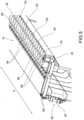
- the blankholder 12 comprises an upper gripping element 14 (visible, for example, in Fig. 9 ) and a lower gripping element 16 having longitudinal development along a direction x.
- the upper gripping element 14 and the lower gripping element 16 are also referred to as the upper crossbar and the lower crossbar, respectively.
- the longitudinal direction x is substantially the direction along which the upper gripping element 14 and the lower gripping element 16 extend.
- the upper gripping element 14 and the lower gripping element 16 are movable relative to each other between a closed position, wherein a panel 18, 20 is clamped between the upper gripping element 14 and the lower gripping element 16, and an open position, wherein the panel 18, 20 may slide between the upper gripping element 14 and the lower gripping element 16.
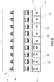
- the lower gripping element 16 comprises a lower operating surface 22 facing said upper gripping element 14. Further, the lower gripping element 16 comprises a plurality of movable plates 24, arranged with a gripping surface 26, along X, and suitable to be moved, each independently of the others, by handling means 25 in a direction substantially perpendicular to the lower operating surface 22, between:
- the lower gripping element 16 is arranged with an array of movable plates 24 suitable for adjusting the actual gripping surface of the lower gripping element 16.
- the gripping distance between the upper gripping element 14 and the movable plates 24 of the lower gripping element 16 is therefore adjustable in such a way that the upper gripping element 14.
- the upper gripping element 14 In the closed position, the upper gripping element 14 is always at the same height as the corresponding upper gripping element 14 of a second blankholder that grips the second panel to be welded.
- the upper gripping element 14 is movable in approach and departure from the lower gripping element 16 to allow the panels to slide.
- the upper gripping element 14 may be fixed, assigning the clamping of the panel to the lower gripping element 16 and/or the movable plates 24.
- the gripping surface 26 of the movable plates 24 may be substantially aligned with the operating surface 22 of the gripping element 16.
- the gripping surface 26 of the movable plates 24 may be in a retracted position relative to the operating surface 22 of the gripping element 24, or protrude therefrom by a predetermined height.
- the gripping surface 26 of the movable plates 24 may be a rectangle.
- the gripping surface 26 may be a square, a circle, an ellipse, or, for example, any combination of straight and/or curved sections.
- Movable plates 24 may be arranged at regular intervals along the direction X on the lower operating surface 22.
- the movable plates 24 may be arranged in a number of four per meter, or in a different number depending on the construction shape of said movable plates 24.
- the movable plates may be substantially rectangular, having a longitudinal dimension of approximately 200 mm and a transverse dimension of approximately 250 mm.
- the movable plates 24 may be spaced 50 mm apart.
- the lower gripping element comprises a guide jig 28 comprising a plurality of sliding seats 30, for example bushings, for a rod 34, at the end of which movable plates 24 are arranged at the lower operating surface 22.
- the movable plate 24 may be connected to its rod 34 by a bolted connection 35.
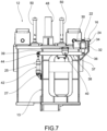
- each rod 34 may be arranged by means of a first end hinge 36 to a first end 37 of a rocker arm 38 according to a direction substantially perpendicular to said X-axis and having a fixed axis of rotation parallel to the X-axis, defined by a fixed central hinge 40, and a corresponding linear actuator 42 (which is seen in the example of Fig. 7 ) connected to a second end 39 of the rocker arm 38 by means of a second end hinge 44.
- the linear actuator 42 that defines the position of the movable plate 24 connected thereto via the rocker arm 38 may be, for example, hydraulic, pneumatic, or electric.
- the linear actuator 42 may be anchored to the support frame 13 of the blankholder 12.
- the linear actuator 42 may be arranged on said frame by means of an actuator hinge 27 such that during the actuation thereof, the actuator may rotate about the actuator hinge 27.
- a first advantage is to move the linear actuator to a safe area away from where the panel clamping is done.
- a second advantage concerns the ease of carrying out any ordinary or extraordinary maintenance operations on the handling means.
- the linear actuator is arranged in an easily accessible position because it is far from the area where the panels are actually picked up.
- the movable plates 24 are suitable to be moved independently of each other, due to the arrangement of independent handling means 25, to adapt to the shape of a panel, which, as in the example of the panel 18, presents a variable thickness in the direction x.
- the variable thickness is represented by the composition of the panel 18 with the sheets 182 and 184.
- the blankholder 12 is suitable to shape itself to grip the edge of the panel 18 having two distinct thicknesses.
- the arrangement of the movable plates at the lower gripping element makes it possible to align the upper surfaces of the panels to be welded with each other, as seen for example in Fig. 12 .
- This description mainly refers to panels having two thicknesses; however, the same blankholder may also be successfully used with panels having more than two different thicknesses, for example three or four or more different thicknesses.
- the blankholder 12 may comprise a programmable control unit 42, which is operatively connected to said handling means 25 for actuating said handling means 25, and consequently automatically adjusting the height of the movable plates 24.
- the height of the movable plates 24 may be adjusted accordingly in an automated manner.
- blankholder handling means 46 comprising guide means 48 and linear actuators 50, 52.
- the blankholder handling means 46 may comprise guide means 48 comprising a guide pin 482 associated with each of the two ends of the upper press element 14, suitable to slide in a corresponding sliding seat 484.
- the sliding pins 482 may be integral with the lower press element 16, and the sliding seats may be associated with the upper press element 14.
- the blankholder handling means 46 may comprise a pair of linear actuators 50, 52 located at the ends of the upper press element 14 and the lower press element 16.
- the pair of linear actuators 50, 52 may be placed on either side of the guide means 48 so that the guide means 48 themselves are central to the linear actuators 50, 52.
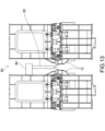
- the present invention further relates to a welding apparatus 80 comprising at least one welding head 82, and at least one blankholder 12 according to the foregoing.
- FIG. 12 and 13 A possible embodiment of a welding apparatus according to the present invention is shown, for example, in Fig. 12 and 13 .
- the welding head may be of a known type, such as a laser welding head, a traditional welding head, MAG, TIG, or electrode.
- the welding head may be arranged on a movable trolley 84, suitable to slide on a respective guide 86 arranged at the structure of one of the two blankholders.
- a blankholder has been provided that allows a panel with variable thickness to be clamped in place without the need for additional support structures.
- a blankholder has been provided that may allow the opening and closing movement of the blankholder to be maintained at the lower gripping element only, while the upper gripping element remains fixed.
- the blankholder according to the present invention makes it possible to automate the welding process even in the case of panels having different thicknesses.
Landscapes
- Engineering & Computer Science (AREA)
- Physics & Mathematics (AREA)
- Mechanical Engineering (AREA)
- Optics & Photonics (AREA)
- Plasma & Fusion (AREA)
- Laser Beam Processing (AREA)
- Arc Welding In General (AREA)
- Butt Welding And Welding Of Specific Article (AREA)
Claims (12)
- Serre-flan (12) pour un appareil de soudage comprenant un élément de serrage supérieur (14) et un élément de serrage inférieur (16) ayant un développement longitudinal le long d'une direction (X), ledit élément de serrage supérieur (14) étant mobile entre une position fermée, dans laquelle un panneau (18, 20) est pris entre ledit élément de serrage supérieur (14) et ledit élément de serrage inférieur (16), et une position ouverte, dans laquelle le panneau (18, 20) peut coulisser entre ledit élément de serrage supérieur (14) et ledit élément de serrage inférieur (16) ; ledit élément de serrage inférieur (16) comprenant une surface fonctionnelle (22) inférieure faisant face audit élément de serrage supérieur (14) ;
caractérisé en ce que
ledit élément de serrage inférieur (16) comprend une pluralité de plaques mobiles (24) agencées le long de ladite direction (X), lesdites plaques mobiles (24) étant appropriées pour être déplacées par des moyens de manutention (25) dans une direction sensiblement perpendiculaire à ladite surface fonctionnelle (22) inférieure, entre une première position, dans laquelle elles ne font pas saillie ou font saillie sur une hauteur minimale par rapport à ladite surface fonctionnelle (22) inférieure, et une seconde position, dans laquelle elles font saillie par rapport à ladite surface fonctionnelle (22) inférieure sur une hauteur maximale prédéterminée, lesdites plaques mobiles (24) étant agencées avec une surface de serrage (26). - Serre-flan (12) selon la revendication précédente, caractérisé en ce que dans ladite première position, ladite surface de serrage (26) desdites plaques mobiles (24) est sensiblement alignée sur ladite surface fonctionnelle (22) dudit élément de serrage (24).
- Serre-flan (12) selon l'une quelconque des revendications précédentes, caractérisé en ce que ladite surface de serrage (26) desdites plaques mobiles (24) est un rectangle.
- Serre-flan (12) selon l'une quelconque des revendications précédentes, caractérisé en ce que lesdites plaques mobiles (24) sont agencées à des intervalles réguliers le long de la direction (X) sur ladite surface fonctionnelle (22) inférieure.
- Serre-flan (12) selon l'une quelconque des revendications précédentes, caractérisé en ce que ledit élément de serrage inférieur comprend un gabarit de guidage (28), comprenant une pluralité de sièges coulissants (30) pour une tige (34) à l'extrémité de laquelle lesdites plaques mobiles (24) sont agencées au niveau de ladite surface fonctionnelle (22) inférieure.
- Serre-flan (12) selon la revendication précédente, caractérisé en ce que chaque tige (34) est agencée au moyen d'une première charnière d'extrémité (36) à une première extrémité (37) d'un bras à bascule (38) conformément à une direction sensiblement perpendiculaire audit axe (X) et ayant un axe fixe de rotation parallèle audit axe (X), défini par une charnière centrale fixe (40), et par un actionneur linéaire (42) correspondant relié à une seconde extrémité (39) dudit bras à bascule (38) au moyen d'une seconde charnière d'extrémité (44).
- Serre-flan (12) selon la revendication précédente, caractérisé en ce que ledit actionneur linéaire (42) est du type hydraulique, pneumatique ou électrique.
- Serre-flan (12) selon l'une quelconque des revendications précédentes, caractérisé en ce que lesdites plaques mobiles (24) sont adaptées pour être déplacées indépendamment les unes des autres, pour s'adapter à la forme d'un panneau (18, 20).
- Serre-flan (12) selon l'une quelconque des revendications précédentes, caractérisé en ce qu'il comprend une unité de commande programmable (42), reliée fonctionnellement auxdits moyens de manutention (25), pour actionner lesdits moyens de manutention (25), et par conséquent ajuster la hauteur desdites plaques mobiles (24).
- Serre-flan (12) selon l'une quelconque des revendications précédentes, caractérisé en ce que ledit élément de serrage supérieur (14) est associé à des moyens de manutention de serre-flan (46) comprenant des moyens de guidage (48) et des actionneurs linéaires (50, 52).
- Appareil de soudage (80) comprenant au moins une tête de soudage (82) et un serre-flan (12) selon l'une quelconque des revendications précédentes.
- Appareil de soudage (80) selon la revendication précédente, caractérisé en ce que ladite tête de soudage (82) est une tête de soudage au laser, une tête de soudage traditionnelle, MAG, TIG ou avec électrode.
Priority Applications (8)
| Application Number | Priority Date | Filing Date | Title |
|---|---|---|---|
| EP22425018.3A EP4260974B1 (fr) | 2022-04-13 | 2022-04-13 | Serre-flan pour un appareil de soudage, et appareil de soudage comprenant ledit serre-flan |
| PL22425018.3T PL4260974T3 (pl) | 2022-04-13 | 2022-04-13 | Docisk blachy do urządzenia spawalniczego oraz urządzenie spawalnicze obejmujące wspomniany docisk blachy |
| FIEP22425018.3T FI4260974T3 (fi) | 2022-04-13 | 2022-04-13 | Aihionpidike hitsauslaitteeseen ja mainitun aihionpidikkeen käsittävä hitsauslaite |
| ES22425018T ES3031865T3 (en) | 2022-04-13 | 2022-04-13 | Blankholder for a welding apparatus, and welding apparatus comprising said blankholder |
| US18/297,714 US20230330789A1 (en) | 2022-04-13 | 2023-04-10 | Blankholder for a welding apparatus, and welding apparatus comprising said blankholder |
| KR1020230048269A KR20230147015A (ko) | 2022-04-13 | 2023-04-12 | 용접 장치를 위한 블랭크홀더 및 상기 블랭크홀더를 포함하는 용접 장치 |
| JP2023064543A JP2023157008A (ja) | 2022-04-13 | 2023-04-12 | 溶接装置用ブランクホルダー、およびそのブランクホルダーを備える溶接装置 |
| CN202310391360.8A CN116900586A (zh) | 2022-04-13 | 2023-04-12 | 焊接设备用的压边机和包括该压边机的焊接设备 |
Applications Claiming Priority (1)
| Application Number | Priority Date | Filing Date | Title |
|---|---|---|---|
| EP22425018.3A EP4260974B1 (fr) | 2022-04-13 | 2022-04-13 | Serre-flan pour un appareil de soudage, et appareil de soudage comprenant ledit serre-flan |
Publications (2)
| Publication Number | Publication Date |
|---|---|
| EP4260974A1 EP4260974A1 (fr) | 2023-10-18 |
| EP4260974B1 true EP4260974B1 (fr) | 2025-03-05 |
Family
ID=82020085
Family Applications (1)
| Application Number | Title | Priority Date | Filing Date |
|---|---|---|---|
| EP22425018.3A Active EP4260974B1 (fr) | 2022-04-13 | 2022-04-13 | Serre-flan pour un appareil de soudage, et appareil de soudage comprenant ledit serre-flan |
Country Status (8)
| Country | Link |
|---|---|
| US (1) | US20230330789A1 (fr) |
| EP (1) | EP4260974B1 (fr) |
| JP (1) | JP2023157008A (fr) |
| KR (1) | KR20230147015A (fr) |
| CN (1) | CN116900586A (fr) |
| ES (1) | ES3031865T3 (fr) |
| FI (1) | FI4260974T3 (fr) |
| PL (1) | PL4260974T3 (fr) |
Families Citing this family (1)
| Publication number | Priority date | Publication date | Assignee | Title |
|---|---|---|---|---|
| CN117773444B (zh) * | 2023-11-24 | 2024-06-21 | 南京海高德新技术有限公司 | 一种车钩安装座高效焊接装置 |
Family Cites Families (2)
| Publication number | Priority date | Publication date | Assignee | Title |
|---|---|---|---|---|
| US5814786A (en) * | 1995-11-08 | 1998-09-29 | Littell International, Inc. | System and method for laser butt-welding |
| JP4636261B2 (ja) * | 2005-10-14 | 2011-02-23 | トヨタ自動車株式会社 | 鋼板の突合せ溶接システム及び鋼板の突合せ溶接方法 |
-
2022
- 2022-04-13 PL PL22425018.3T patent/PL4260974T3/pl unknown
- 2022-04-13 EP EP22425018.3A patent/EP4260974B1/fr active Active
- 2022-04-13 ES ES22425018T patent/ES3031865T3/es active Active
- 2022-04-13 FI FIEP22425018.3T patent/FI4260974T3/fi active
-
2023
- 2023-04-10 US US18/297,714 patent/US20230330789A1/en active Pending
- 2023-04-12 KR KR1020230048269A patent/KR20230147015A/ko active Pending
- 2023-04-12 JP JP2023064543A patent/JP2023157008A/ja active Pending
- 2023-04-12 CN CN202310391360.8A patent/CN116900586A/zh active Pending
Also Published As
| Publication number | Publication date |
|---|---|
| PL4260974T3 (pl) | 2025-06-16 |
| US20230330789A1 (en) | 2023-10-19 |
| JP2023157008A (ja) | 2023-10-25 |
| ES3031865T3 (en) | 2025-07-11 |
| CN116900586A (zh) | 2023-10-20 |
| KR20230147015A (ko) | 2023-10-20 |
| EP4260974A1 (fr) | 2023-10-18 |
| FI4260974T3 (fi) | 2025-05-21 |
Similar Documents
| Publication | Publication Date | Title |
|---|---|---|
| EP3717173B1 (fr) | Ensemble de fixation et procédé pour opérations de soudage | |
| DE69403932T2 (de) | Bearbeitungsstation mit Stümpfpositionierung und Laserstrahlschweissen von zwei Blechkanten | |
| EP1830982B1 (fr) | Dispositif de serrage d'au moins deux composants, notamment de composants d'aeronefs, pour la connexion des composants par l'intermediaire d'un cordon de soudure forme par soudage par friction et agitation entre deux aretes de composants | |
| US7735706B2 (en) | Apparatus for the connection of strips | |
| DE69304112T2 (de) | Gerät und Verfahren zur Herstellung zweier oder mehrerer verschiedenen Arten geschweisster Paneele | |
| EP0163219A1 (fr) | Plaque porteuse avec dispositif de serrage | |
| AT8674U1 (de) | Blechbiegeeinrichtung mit einer ablagevorrichtung | |
| EP4260974B1 (fr) | Serre-flan pour un appareil de soudage, et appareil de soudage comprenant ledit serre-flan | |
| EP0583449A1 (fr) | Presse a plier | |
| US5927135A (en) | Bending machine | |
| DE3622922C2 (fr) | ||
| DE202008007548U1 (de) | Spannvorrichtung | |
| EP1674197B1 (fr) | Dispositif d'alimentation des panneaux | |
| WO1998014288A1 (fr) | Machine a usiner | |
| KR102682561B1 (ko) | 가공부재 지지유닛 및 이를 포함하는 레이저 가공장치 | |
| AT505815B1 (de) | Vorrichtung und verfahren zum punktschweissen von zwei flächigen bauteilen | |
| DE69412641T2 (de) | Räumliches einstellgerät einer einrichtung, zum blechschweissen | |
| EP0100283A2 (fr) | Porte-outil universel pour plaques de métal | |
| NL2004384C2 (en) | A PRESS BRAKE FOR BENDING SHEETS. | |
| EP1731256B1 (fr) | Table de travail laser avec des éléments de support de pièces déplaçables | |
| EP2060337B1 (fr) | Dispositif destiné à la liaison sur le bord de tôles | |
| AT399303B (de) | Abkantpressensystem, einrichtung zum handhaben von blechen, vorrichtung und verfahren zum geraderichten von blechen | |
| JPH0614943Y2 (ja) | 長尺材溶接治具 | |
| EP3558557B1 (fr) | Dispositif et procédé de façonnage d'une tôle | |
| CN121666288A (zh) | 用于工件的夹紧装置 |
Legal Events
| Date | Code | Title | Description |
|---|---|---|---|
| PUAI | Public reference made under article 153(3) epc to a published international application that has entered the european phase |
Free format text: ORIGINAL CODE: 0009012 |
|
| STAA | Information on the status of an ep patent application or granted ep patent |
Free format text: STATUS: THE APPLICATION HAS BEEN PUBLISHED |
|
| AK | Designated contracting states |
Kind code of ref document: A1 Designated state(s): AL AT BE BG CH CY CZ DE DK EE ES FI FR GB GR HR HU IE IS IT LI LT LU LV MC MK MT NL NO PL PT RO RS SE SI SK SM TR |
|
| STAA | Information on the status of an ep patent application or granted ep patent |
Free format text: STATUS: REQUEST FOR EXAMINATION WAS MADE |
|
| 17P | Request for examination filed |
Effective date: 20240118 |
|
| RBV | Designated contracting states (corrected) |
Designated state(s): AL AT BE BG CH CY CZ DE DK EE ES FI FR GB GR HR HU IE IS IT LI LT LU LV MC MK MT NL NO PL PT RO RS SE SI SK SM TR |
|
| GRAP | Despatch of communication of intention to grant a patent |
Free format text: ORIGINAL CODE: EPIDOSNIGR1 |
|
| STAA | Information on the status of an ep patent application or granted ep patent |
Free format text: STATUS: GRANT OF PATENT IS INTENDED |
|
| RIC1 | Information provided on ipc code assigned before grant |
Ipc: B23K 37/04 20060101AFI20240326BHEP |
|
| INTG | Intention to grant announced |
Effective date: 20240429 |
|
| GRAJ | Information related to disapproval of communication of intention to grant by the applicant or resumption of examination proceedings by the epo deleted |
Free format text: ORIGINAL CODE: EPIDOSDIGR1 |
|
| STAA | Information on the status of an ep patent application or granted ep patent |
Free format text: STATUS: REQUEST FOR EXAMINATION WAS MADE |
|
| GRAP | Despatch of communication of intention to grant a patent |
Free format text: ORIGINAL CODE: EPIDOSNIGR1 |
|
| STAA | Information on the status of an ep patent application or granted ep patent |
Free format text: STATUS: GRANT OF PATENT IS INTENDED |
|
| INTC | Intention to grant announced (deleted) | ||
| P01 | Opt-out of the competence of the unified patent court (upc) registered |
Free format text: CASE NUMBER: APP_50383/2024 Effective date: 20240905 |
|
| INTG | Intention to grant announced |
Effective date: 20240925 |
|
| GRAS | Grant fee paid |
Free format text: ORIGINAL CODE: EPIDOSNIGR3 |
|
| GRAA | (expected) grant |
Free format text: ORIGINAL CODE: 0009210 |
|
| STAA | Information on the status of an ep patent application or granted ep patent |
Free format text: STATUS: THE PATENT HAS BEEN GRANTED |
|
| AK | Designated contracting states |
Kind code of ref document: B1 Designated state(s): AL AT BE BG CH CY CZ DE DK EE ES FI FR GB GR HR HU IE IS IT LI LT LU LV MC MK MT NL NO PL PT RO RS SE SI SK SM TR |
|
| REG | Reference to a national code |
Ref country code: GB Ref legal event code: FG4D |
|
| REG | Reference to a national code |
Ref country code: CH Ref legal event code: EP |
|
| REG | Reference to a national code |
Ref country code: DE Ref legal event code: R096 Ref document number: 602022011400 Country of ref document: DE |
|
| REG | Reference to a national code |
Ref country code: IE Ref legal event code: FG4D |
|
| REG | Reference to a national code |
Ref country code: DE Ref legal event code: R081 Ref document number: 602022011400 Country of ref document: DE Owner name: FINCANTIERI S.P.A., IT Free format text: FORMER OWNERS: CASTELLINI OFFICINE MECCANICHE S.R.L., CAZZAGO SAN MARTINO, BRESCIA, IT; FINCANTIERI S.P.A., TRIESTE, IT Ref country code: DE Ref legal event code: R081 Ref document number: 602022011400 Country of ref document: DE Owner name: CASTELLINI S.P.A. SOCIETA' BENEFIT, CAZZAGO SA, IT Free format text: FORMER OWNERS: CASTELLINI OFFICINE MECCANICHE S.R.L., CAZZAGO SAN MARTINO, BRESCIA, IT; FINCANTIERI S.P.A., TRIESTE, IT |
|
| PGFP | Annual fee paid to national office [announced via postgrant information from national office to epo] |
Ref country code: NL Payment date: 20250430 Year of fee payment: 4 |
|
| REG | Reference to a national code |
Ref country code: FI Ref legal event code: FGE |
|
| REG | Reference to a national code |
Ref country code: NL Ref legal event code: PD Owner name: FINCANTIERI S.P.A.; IT Free format text: DETAILS ASSIGNMENT: CHANGE OF OWNER(S), ASSIGNMENT; FORMER OWNER NAME: FINCANTIERI S.P.A. Effective date: 20250519 Ref country code: NL Ref legal event code: FP |
|
| RAP2 | Party data changed (patent owner data changed or rights of a patent transferred) |
Owner name: FINCANTIERI S.P.A. Owner name: CASTELLINI S.P.A. SOCIETA' BENEFIT |
|
| PG25 | Lapsed in a contracting state [announced via postgrant information from national office to epo] |
Ref country code: RS Free format text: LAPSE BECAUSE OF FAILURE TO SUBMIT A TRANSLATION OF THE DESCRIPTION OR TO PAY THE FEE WITHIN THE PRESCRIBED TIME-LIMIT Effective date: 20250605 |
|
| PGFP | Annual fee paid to national office [announced via postgrant information from national office to epo] |
Ref country code: FI Payment date: 20250616 Year of fee payment: 4 |
|
| PGFP | Annual fee paid to national office [announced via postgrant information from national office to epo] |
Ref country code: PL Payment date: 20250430 Year of fee payment: 4 Ref country code: DE Payment date: 20250429 Year of fee payment: 4 |
|
| PGFP | Annual fee paid to national office [announced via postgrant information from national office to epo] |
Ref country code: ES Payment date: 20250505 Year of fee payment: 4 |
|
| REG | Reference to a national code |
Ref country code: LT Ref legal event code: MG9D |
|
| REG | Reference to a national code |
Ref country code: ES Ref legal event code: FG2A Ref document number: 3031865 Country of ref document: ES Kind code of ref document: T3 Effective date: 20250711 |
|
| PGFP | Annual fee paid to national office [announced via postgrant information from national office to epo] |
Ref country code: NO Payment date: 20250519 Year of fee payment: 4 |
|
| PG25 | Lapsed in a contracting state [announced via postgrant information from national office to epo] |
Ref country code: HR Free format text: LAPSE BECAUSE OF FAILURE TO SUBMIT A TRANSLATION OF THE DESCRIPTION OR TO PAY THE FEE WITHIN THE PRESCRIBED TIME-LIMIT Effective date: 20250305 |
|
| PG25 | Lapsed in a contracting state [announced via postgrant information from national office to epo] |
Ref country code: LV Free format text: LAPSE BECAUSE OF FAILURE TO SUBMIT A TRANSLATION OF THE DESCRIPTION OR TO PAY THE FEE WITHIN THE PRESCRIBED TIME-LIMIT Effective date: 20250305 |
|
| PG25 | Lapsed in a contracting state [announced via postgrant information from national office to epo] |
Ref country code: BG Free format text: LAPSE BECAUSE OF FAILURE TO SUBMIT A TRANSLATION OF THE DESCRIPTION OR TO PAY THE FEE WITHIN THE PRESCRIBED TIME-LIMIT Effective date: 20250305 Ref country code: GR Free format text: LAPSE BECAUSE OF FAILURE TO SUBMIT A TRANSLATION OF THE DESCRIPTION OR TO PAY THE FEE WITHIN THE PRESCRIBED TIME-LIMIT Effective date: 20250606 |
|
| PGFP | Annual fee paid to national office [announced via postgrant information from national office to epo] |
Ref country code: RO Payment date: 20250430 Year of fee payment: 4 |
|
| REG | Reference to a national code |
Ref country code: AT Ref legal event code: MK05 Ref document number: 1772509 Country of ref document: AT Kind code of ref document: T Effective date: 20250305 |
|
| PG25 | Lapsed in a contracting state [announced via postgrant information from national office to epo] |
Ref country code: SE Free format text: LAPSE BECAUSE OF FAILURE TO SUBMIT A TRANSLATION OF THE DESCRIPTION OR TO PAY THE FEE WITHIN THE PRESCRIBED TIME-LIMIT Effective date: 20250305 |
|
| PG25 | Lapsed in a contracting state [announced via postgrant information from national office to epo] |
Ref country code: SM Free format text: LAPSE BECAUSE OF FAILURE TO SUBMIT A TRANSLATION OF THE DESCRIPTION OR TO PAY THE FEE WITHIN THE PRESCRIBED TIME-LIMIT Effective date: 20250305 |
|
| PG25 | Lapsed in a contracting state [announced via postgrant information from national office to epo] |
Ref country code: PT Free format text: LAPSE BECAUSE OF FAILURE TO SUBMIT A TRANSLATION OF THE DESCRIPTION OR TO PAY THE FEE WITHIN THE PRESCRIBED TIME-LIMIT Effective date: 20250707 |
|
| PG25 | Lapsed in a contracting state [announced via postgrant information from national office to epo] |
Ref country code: AT Free format text: LAPSE BECAUSE OF FAILURE TO SUBMIT A TRANSLATION OF THE DESCRIPTION OR TO PAY THE FEE WITHIN THE PRESCRIBED TIME-LIMIT Effective date: 20250305 |
|
| PG25 | Lapsed in a contracting state [announced via postgrant information from national office to epo] |
Ref country code: EE Free format text: LAPSE BECAUSE OF FAILURE TO SUBMIT A TRANSLATION OF THE DESCRIPTION OR TO PAY THE FEE WITHIN THE PRESCRIBED TIME-LIMIT Effective date: 20250305 Ref country code: CZ Free format text: LAPSE BECAUSE OF FAILURE TO SUBMIT A TRANSLATION OF THE DESCRIPTION OR TO PAY THE FEE WITHIN THE PRESCRIBED TIME-LIMIT Effective date: 20250305 |
|
| PG25 | Lapsed in a contracting state [announced via postgrant information from national office to epo] |
Ref country code: SK Free format text: LAPSE BECAUSE OF FAILURE TO SUBMIT A TRANSLATION OF THE DESCRIPTION OR TO PAY THE FEE WITHIN THE PRESCRIBED TIME-LIMIT Effective date: 20250305 |
|
| PG25 | Lapsed in a contracting state [announced via postgrant information from national office to epo] |
Ref country code: IS Free format text: LAPSE BECAUSE OF FAILURE TO SUBMIT A TRANSLATION OF THE DESCRIPTION OR TO PAY THE FEE WITHIN THE PRESCRIBED TIME-LIMIT Effective date: 20250705 |
|
| REG | Reference to a national code |
Ref country code: CH Ref legal event code: H13 Free format text: ST27 STATUS EVENT CODE: U-0-0-H10-H13 (AS PROVIDED BY THE NATIONAL OFFICE) Effective date: 20251125 |
|
| REG | Reference to a national code |
Ref country code: DE Ref legal event code: R097 Ref document number: 602022011400 Country of ref document: DE |
|
| PG25 | Lapsed in a contracting state [announced via postgrant information from national office to epo] |
Ref country code: LU Free format text: LAPSE BECAUSE OF NON-PAYMENT OF DUE FEES Effective date: 20250413 |
|
| PG25 | Lapsed in a contracting state [announced via postgrant information from national office to epo] |
Ref country code: MC Free format text: LAPSE BECAUSE OF FAILURE TO SUBMIT A TRANSLATION OF THE DESCRIPTION OR TO PAY THE FEE WITHIN THE PRESCRIBED TIME-LIMIT Effective date: 20250305 |
|
| REG | Reference to a national code |
Ref country code: BE Ref legal event code: MM Effective date: 20250430 |
|
| PLBE | No opposition filed within time limit |
Free format text: ORIGINAL CODE: 0009261 |
|
| STAA | Information on the status of an ep patent application or granted ep patent |
Free format text: STATUS: NO OPPOSITION FILED WITHIN TIME LIMIT |
|
| PG25 | Lapsed in a contracting state [announced via postgrant information from national office to epo] |
Ref country code: DK Free format text: LAPSE BECAUSE OF FAILURE TO SUBMIT A TRANSLATION OF THE DESCRIPTION OR TO PAY THE FEE WITHIN THE PRESCRIBED TIME-LIMIT Effective date: 20250305 |
|
| REG | Reference to a national code |
Ref country code: CH Ref legal event code: L10 Free format text: ST27 STATUS EVENT CODE: U-0-0-L10-L00 (AS PROVIDED BY THE NATIONAL OFFICE) Effective date: 20260114 |
|
| PG25 | Lapsed in a contracting state [announced via postgrant information from national office to epo] |
Ref country code: BE Free format text: LAPSE BECAUSE OF NON-PAYMENT OF DUE FEES Effective date: 20250430 |
|
| PG25 | Lapsed in a contracting state [announced via postgrant information from national office to epo] |
Ref country code: CH Free format text: LAPSE BECAUSE OF NON-PAYMENT OF DUE FEES Effective date: 20250430 |
|
| 26N | No opposition filed |
Effective date: 20251208 |
|
| PG25 | Lapsed in a contracting state [announced via postgrant information from national office to epo] |
Ref country code: IE Free format text: LAPSE BECAUSE OF NON-PAYMENT OF DUE FEES Effective date: 20250413 |
|
| PGFP | Annual fee paid to national office [announced via postgrant information from national office to epo] |
Ref country code: IT Payment date: 20260306 Year of fee payment: 5 |
|
| PGFP | Annual fee paid to national office [announced via postgrant information from national office to epo] |
Ref country code: FR Payment date: 20260331 Year of fee payment: 5 |