EP4261006B1 - Zieh- und kühlstab zur herstellung von behältern - Google Patents
Zieh- und kühlstab zur herstellung von behältern Download PDFInfo
- Publication number
- EP4261006B1 EP4261006B1 EP23159164.5A EP23159164A EP4261006B1 EP 4261006 B1 EP4261006 B1 EP 4261006B1 EP 23159164 A EP23159164 A EP 23159164A EP 4261006 B1 EP4261006 B1 EP 4261006B1
- Authority
- EP
- European Patent Office
- Prior art keywords
- stretching rod
- preform
- rod
- container
- stretching
- Prior art date
- Legal status (The legal status is an assumption and is not a legal conclusion. Google has not performed a legal analysis and makes no representation as to the accuracy of the status listed.)
- Active
Links
Images




Classifications
-
- B—PERFORMING OPERATIONS; TRANSPORTING
- B29—WORKING OF PLASTICS; WORKING OF SUBSTANCES IN A PLASTIC STATE IN GENERAL
- B29C—SHAPING OR JOINING OF PLASTICS; SHAPING OF MATERIAL IN A PLASTIC STATE, NOT OTHERWISE PROVIDED FOR; AFTER-TREATMENT OF THE SHAPED PRODUCTS, e.g. REPAIRING
- B29C49/00—Blow-moulding, i.e. blowing a preform or parison to a desired shape within a mould; Apparatus therefor
- B29C49/08—Biaxial stretching during blow-moulding
- B29C49/10—Biaxial stretching during blow-moulding using mechanical means for prestretching
- B29C49/12—Stretching rods
-
- B—PERFORMING OPERATIONS; TRANSPORTING
- B29—WORKING OF PLASTICS; WORKING OF SUBSTANCES IN A PLASTIC STATE IN GENERAL
- B29C—SHAPING OR JOINING OF PLASTICS; SHAPING OF MATERIAL IN A PLASTIC STATE, NOT OTHERWISE PROVIDED FOR; AFTER-TREATMENT OF THE SHAPED PRODUCTS, e.g. REPAIRING
- B29C49/00—Blow-moulding, i.e. blowing a preform or parison to a desired shape within a mould; Apparatus therefor
- B29C49/08—Biaxial stretching during blow-moulding
- B29C49/10—Biaxial stretching during blow-moulding using mechanical means for prestretching
- B29C49/12—Stretching rods
- B29C49/121—Stretching rod configuration, e.g. geometry; Stretching rod material
- B29C49/1212—Stretching rod configuration, e.g. geometry; Stretching rod material the stretching rod comprising at least one opening on the surface, e.g. through which compressed air is blown into the preform to expand the same
-
- B—PERFORMING OPERATIONS; TRANSPORTING
- B29—WORKING OF PLASTICS; WORKING OF SUBSTANCES IN A PLASTIC STATE IN GENERAL
- B29C—SHAPING OR JOINING OF PLASTICS; SHAPING OF MATERIAL IN A PLASTIC STATE, NOT OTHERWISE PROVIDED FOR; AFTER-TREATMENT OF THE SHAPED PRODUCTS, e.g. REPAIRING
- B29C49/00—Blow-moulding, i.e. blowing a preform or parison to a desired shape within a mould; Apparatus therefor
- B29C49/08—Biaxial stretching during blow-moulding
- B29C49/10—Biaxial stretching during blow-moulding using mechanical means for prestretching
- B29C49/12—Stretching rods
- B29C49/121—Stretching rod configuration, e.g. geometry; Stretching rod material
- B29C49/1215—Geometry of the stretching rod, e.g. specific stretching rod end shape
-
- B—PERFORMING OPERATIONS; TRANSPORTING
- B29—WORKING OF PLASTICS; WORKING OF SUBSTANCES IN A PLASTIC STATE IN GENERAL
- B29C—SHAPING OR JOINING OF PLASTICS; SHAPING OF MATERIAL IN A PLASTIC STATE, NOT OTHERWISE PROVIDED FOR; AFTER-TREATMENT OF THE SHAPED PRODUCTS, e.g. REPAIRING
- B29C49/00—Blow-moulding, i.e. blowing a preform or parison to a desired shape within a mould; Apparatus therefor
- B29C49/42—Component parts, details or accessories; Auxiliary operations
- B29C49/64—Heating or cooling preforms, parisons or blown articles
- B29C49/66—Cooling by refrigerant introduced into the blown article
-
- B—PERFORMING OPERATIONS; TRANSPORTING
- B29—WORKING OF PLASTICS; WORKING OF SUBSTANCES IN A PLASTIC STATE IN GENERAL
- B29C—SHAPING OR JOINING OF PLASTICS; SHAPING OF MATERIAL IN A PLASTIC STATE, NOT OTHERWISE PROVIDED FOR; AFTER-TREATMENT OF THE SHAPED PRODUCTS, e.g. REPAIRING
- B29C49/00—Blow-moulding, i.e. blowing a preform or parison to a desired shape within a mould; Apparatus therefor
- B29C49/42—Component parts, details or accessories; Auxiliary operations
- B29C49/64—Heating or cooling preforms, parisons or blown articles
- B29C49/6604—Thermal conditioning of the blown article
-
- B—PERFORMING OPERATIONS; TRANSPORTING
- B29—WORKING OF PLASTICS; WORKING OF SUBSTANCES IN A PLASTIC STATE IN GENERAL
- B29C—SHAPING OR JOINING OF PLASTICS; SHAPING OF MATERIAL IN A PLASTIC STATE, NOT OTHERWISE PROVIDED FOR; AFTER-TREATMENT OF THE SHAPED PRODUCTS, e.g. REPAIRING
- B29C49/00—Blow-moulding, i.e. blowing a preform or parison to a desired shape within a mould; Apparatus therefor
- B29C49/42—Component parts, details or accessories; Auxiliary operations
- B29C49/64—Heating or cooling preforms, parisons or blown articles
- B29C49/6604—Thermal conditioning of the blown article
- B29C2049/6606—Cooling the article
-
- B—PERFORMING OPERATIONS; TRANSPORTING
- B29—WORKING OF PLASTICS; WORKING OF SUBSTANCES IN A PLASTIC STATE IN GENERAL
- B29C—SHAPING OR JOINING OF PLASTICS; SHAPING OF MATERIAL IN A PLASTIC STATE, NOT OTHERWISE PROVIDED FOR; AFTER-TREATMENT OF THE SHAPED PRODUCTS, e.g. REPAIRING
- B29C49/00—Blow-moulding, i.e. blowing a preform or parison to a desired shape within a mould; Apparatus therefor
- B29C49/02—Combined blow-moulding and manufacture of the preform or the parison
- B29C49/06—Injection blow-moulding
-
- B—PERFORMING OPERATIONS; TRANSPORTING
- B29—WORKING OF PLASTICS; WORKING OF SUBSTANCES IN A PLASTIC STATE IN GENERAL
- B29K—INDEXING SCHEME ASSOCIATED WITH SUBCLASSES B29B, B29C OR B29D, RELATING TO MOULDING MATERIALS OR TO MATERIALS FOR MOULDS, REINFORCEMENTS, FILLERS OR PREFORMED PARTS, e.g. INSERTS
- B29K2067/00—Use of polyesters or derivatives thereof, as moulding material
- B29K2067/003—PET, i.e. poylethylene terephthalate
-
- B—PERFORMING OPERATIONS; TRANSPORTING
- B29—WORKING OF PLASTICS; WORKING OF SUBSTANCES IN A PLASTIC STATE IN GENERAL
- B29L—INDEXING SCHEME ASSOCIATED WITH SUBCLASS B29C, RELATING TO PARTICULAR ARTICLES
- B29L2031/00—Other particular articles
- B29L2031/712—Containers; Packaging elements or accessories, Packages
- B29L2031/7158—Bottles
Definitions
- the present invention relates to the field of manufacturing containers by blow molding or stretch blow molding from preforms made of thermoplastic material, such as for example polyethylene terephthalate, hereinafter "PET". Its subject more particularly is a stretching and cooling rod intended to be implemented in a stretch blow molding technique for forming containers. It also relates to a method for manufacturing containers using the stretching and cooling rod according to the invention.
- a stretching rod according to the prior art and a method using such a rod are described in the documents US2021/107205A1 , US2011/193271A1 , US5213752A And EP0036844A1 .
- a forming device which comprises a mold having a cavity shaped to the imprint of the container to be obtained.
- the preheated preform is received in the cavity.
- its walls are subjected to a so-called "biaxial” stretching to fit the imprint of the mold.
- the preform is stretched axially by means of a stretching rod to cause the axial expansion of the preform.
- a pressurized fluid is injected into the preform so as to cause the radial expansion of the wall.
- the drawing rod In order for the final container to have a perfectly moulded bottom, it is preferable for the drawing rod to be adapted to ensure a satisfactory thickness of the container wall. Poor material distribution is a recurring defect found in containers produced by a moulding and stretch/blow moulding process. It is not necessarily a matter of ensuring that the thickness of the container wall is constant, as in some cases it may be desirable to thicken certain areas, in particular those intended to undergo significant stresses (in particular near the bottom). Rather, it is a matter of ensuring that the material thickness corresponds to the specifications of the container, as defined according to its shape and use.
- a material defect located in the center can also generate hotter areas that are sensitive to sagging.
- an additional internal cooling step can be very useful. This step consists of generating cooling of the base by the drawing rod, at the end of the phase of blowing, over a very short time, at very localized places on the bottom.
- JP2001088202 proposes a drawing and cooling rod, having orifices specifically provided for cooling the bottom of a preform. These orifices are located on the body of the rod, above the end piece formed at the end of said rod. The end piece is designed to be placed in contact with the bottom of the preform during drawing, then slightly set back during the cooling phase, to allow the gas to escape from the orifices and, by this effect, cool the bottom, at the end of the blowing phase.
- the cooling gas escapes in a poorly controlled manner, and is not directed precisely, in a localized manner towards the bottom of the container obtained.
- the invention aims to solve this problem and proposes, for this purpose, a drawing rod which ensures drawing of the preform along its axis, avoiding undesirable contacts between the outside of the rod and the inside of the body of the preform, while improving the distribution of the cooling gas, in particular on the bottom of the container obtained.
- the trajectory of the cooling gas is controlled and mastered thanks to the use of a drawing rod in accordance with the invention.
- Said stretching rod is characterized in that it comprises an annular skirt in the extension of said body, at said distal end, said skirt having a height less than the height of said tip.
- edges of the skirt and/or the end of the projecting tip of the drawing rod are rounded.
- the outer body and the skirt comprise a single piece.
- the tip of the drawing rod is conical in shape.
- the flat extends orthogonally to the major Y axis.
- the orifices are oriented outwardly in the direction of the main axis Y, and at an angle between 1 and 50 degrees, preferably at an angle of 30 degrees.
- the annular skirt of the drawing rod has a crenellated shape.
- the annular skirt of the drawing rod has a crenellated shape with rounded, convex crest edges and concave trough edges.
- the flat of the stretching rod has a recess in the shape of an internal rosette.
- the invention is designed to be implemented in a container manufacturing installation 2.
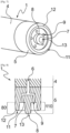
- a container manufacturing installation usually comprises a molding machine as shown in [ Fig.1 ], comprising at least molding units 18, each molding unit 18 comprising at least blowing means integrating a stretching rod 1, said mold 14 comprising at least two half-molds 140 which each comprise an internal molding face and which are respectively mounted on supports 142 movable around an axis Y, between at least one open position and a closed position of the molding unit 18, in which said internal faces of said at least two joint half-molds 140 together delimit a molding cavity 15 of the container 2.
- blow molds 14 are distributed circularly, in the form of a carousel 170, as visible in [ Fig.1 ], and topped by respective blowing installations.
- body of the blowing installation extends substantially vertically above the mold and substantially coaxially with the molding cavity 15 of the blowing mold 14.
- FIG.2 schematically represents a perspective view of one of the molding units 18 of the machine according to the exemplary embodiment of the [ Fig.1 ], illustrating in particular, outside the unit in the open position, an exploded view of a mold 14 made in three parts, namely two half-molds 140 and a mold base 141.
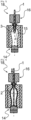
- FIG.3 showing a first embodiment of a rod 1 according to the invention, in partial longitudinal section view, which is implemented with a preform 3 made of PET or recycled PET, intended to be stretched and blown in one of the blow molds 14 of an installation briefly described above, so as to form a container 2, such as a bottle.
- the stretching rod 1 is in the high position and being inserted into the preform 3.
- the rod 1 is designed to be mounted in the body of the blowing installation also mentioned above.
- Said stretching rod 1 extends longitudinally, parallel to the main axis Y.
- the stretching rod 1 according to the invention is a hollow stretching rod, which then provides a dual function, a stretching function on the one hand and another function of cooling the container on the other hand. To do this, it has a first so-called proximal end (not shown) capable of being secured to a displacement device internal to the manufacturing installation.
- the preform 3 comprises, in a conventional manner, an elongated, tubular body with an axis Y, limited by a wall 31 secured in the upper part to a threaded neck 32 and in the lower part to a substantially hemispherical base 30.
- a radial collar 33 projects towards the outside of the preform 3.
- the preform 3 illustrated in [ Fig.6 ] has a symmetry of revolution around its Y axis.
- the Y axis of the rod 1 is substantially coincident with the axis of revolution of the preform 3.
- the axis of the rod 1 or that of the preform 3 will therefore be referred to indifferently as Y.
- any direction parallel to the axis of revolution of the rod will be called “vertical” and any direction perpendicular to the axis of revolution of the rod will be called “transverse”.
- the drawing rod 1 comprises a cylindrical or tubular body 4.
- the body 4 of the drawing rod 1 may have a shoulder, i.e. have two longitudinal sections having two different diameters. This is particularly advantageous for blowing small diameter preforms.
- the body 4 also comprises a central inner channel 6 extending axially and communicating with a plurality of orifices 9 through which a cooling gas 10, in particular air, is injected into the interior of the manufactured container 2 in order to cool it.
- the orifices 9 are therefore in fluid communication with the inner channel 6.
- the stretching rod 1 In the extension of the body 4, at the level of the distal end 5, the stretching rod 1 comprises a flat 7. An end piece 8 projects from this flat 7.
- the stretching rod 1 further comprises an annular skirt 11 in the extension of its body 4.
- FIG.4 schematically represents another step of a blowing cycle, in which the stretching rod 1 is in the low position and therefore placed at the bottom of the preform 3 during the blowing step. During this step, the preform 3 becomes a container 2.
- FIG.5 schematically represents an embodiment of another step of a blowing cycle, in which the stretching rod 1, still in the low position, carries out the cooling step, called the sweeping phase, of the container 2 thus formed by injection of the cooling gas 10.
- the cooling gas 10 will then pass through the internal channel 6 of the stretching rod 1 to diffuse locally and precisely on the bottom of the container 2.
- the injection of the cooling gas 10 is represented in the form of arrows on the [ Fig.5 ].
- the diameter of the annular skirt 11 is equal to the diameter of the body 4 of the drawing rod 1.
- the cooling gas 10 is directed in a very localized manner.
- the outer body 4 and the annular skirt 11 are obtained in one piece. In other words, they form a single piece.
- the outer body 4 and the annular skirt 11 are two separate parts.
- the structural modifications of the drawing rod 1 have the advantageous effect of directing the cooling gas 10 towards the bottom of the container 2, over its entire lower surface, and thus of improving the cooling step.
- the orifices 9 are for example of cylindrical shape and preferably have a diameter of between 0.3 and 3 millimeters (mm). They can also be of another shape, for example oblong.
- the injection surface is between 3 and 6 square millimeters (mm 2 ) and does not exceed 20 square millimeters (mm 2 ).
- the injection surface corresponds to the sum of the diameters of the orifices 9. It represents the quantity of cooling gas 10 that can be injected thanks to the configuration of the rod 1, comprising orifices 9 acting as restriction orifices.
- the drawing rod 1 in fact has a very low dead volume and a design optimized for the internal cooling of a blown container 2.
- the stretching rod 1 therefore has a plurality of orifices 9 arranged on the flat 7.
- the projecting end piece 8 can be of any shape.
- said end piece 8 can be of conical shape, rounded conical shape, ovoid shape, hemispherical shape, etc.
- the flat 7 is perpendicular to the body 4 of the drawing rod 1. This allows better distribution and better control of the cooling gas 10 which then escapes from the orifices 9 in a homogeneous manner.
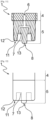
- FIG.8 schematically represents a view along a longitudinal median section of an exemplary embodiment of the distal end of the drawing rod 1, showing in particular an annular skirt 11 having rounded edges and a cylindrical tip 8.
- the edges 12 of the annular skirt 11 are rounded. This is particularly advantageous because it makes it possible to avoid any risk of tearing if said edges 12 were to touch the wall of the preform 3, for example during the drawing phase.
- This variant of rounded edges 12 of the skirt 11 can also be applied to the other embodiments of the invention.
- the annular skirt 11 has the same diameter as the diameter of the body 4 of the drawing rod 1.
- On the flat 7 are arranged, around the projecting end piece 8, five orifices 9.
- the annular skirt 11 has a height 110 less than the height 80 of the tip 8 so that said tip 8 projects from the annular skirt 11.
- the distal end of the drawing rod 1 is formed by the tip 8 and the annular skirt 11 is an extension of the outer body 4 relative to the flat 7. This makes it possible to direct the cooling gas 10 in a controlled manner when it leaves the inner channel 6 through the orifices 9.
- the height 110 of the annular skirt 11 is less than the height 80 of the end piece 8 by a value between 0.5 and 4 millimeters (mm), even more preferably by a value of 1 mm.
- the height 110 of the annular skirt 11 varies across its circumference.
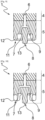
- the annular skirt 11 may have serrated or scalloped edges, and thus have valleys and ridges, as seen in the [ Fig.13 ]. However, in this case, the height 110 remains lower than the height 80 of tip 8.
- FIG.8 schematically represents a view along a longitudinal median section of the first embodiment of the [ Fig.7 ].
- the inner channel 6 divides into different sections to open onto the orifices 9.
- the cooling step is an additional step in a process for manufacturing PET and recycled PET (“rPET”) containers.
- the flow of the cooling gas 10 is schematically shown in [ Fig.5 ] by arrows.
- This cooling step makes it possible in particular to reduce the internal temperature of the container obtained, and aims to limit the transfer of heat from the internal to the external after the container 2 obtained has been removed from the mold. This also makes it possible to limit the collapse of the bottom, this collapse generally having a negative impact on stress, which increases the risk of rejects. Indeed, a bottom having too high a temperature will tend to collapse during the mold removal step. The container 2 obtained may then potentially have leaks or other defects.
- the presence of the annular skirt 11 according to the invention has the advantage of considerably improving the cooling step by amplifying the action of the injected cooling gas 10, the gas being directed in a localized manner where its presence is necessary. This then makes it possible to considerably improve the cooling step of the container 2 obtained, and therefore to achieve optimal cooling, even when, for reasons of rate, the duration of the cooling step must be very short.
- the holes 9 are oriented obliquely, outwards in the direction of the main axis Y, towards the bottom of the blank at a deviation of 1 to 50 degrees.
- the orifices 9 are oriented outwards in the direction of the main axis Y, by a deviation of 30 degrees.
- the orientation of the orifices allows the cooling gas 10 to be distributed homogeneously towards the bottom of the preform 3 and therefore towards the bottom of the container 2 thus formed, that is to say over its entire surface.
- this makes it possible to further improve the cooling of the bottom, where the latter has the highest temperatures, and therefore where stress zones, favored by its subsidence, are likely to develop.
- the skirt 11 has rounded edges and the holes 9 of the rod are oriented at an angle.
- the annular skirt 11 of the drawing rod 1 has straight and beveled edges. This embodiment is illustrated in [ Fig.9 ].
- the annular skirt 11 has a crenellated shape with rounded and convex crest edges and concave trough edges.
- the orifices 9 may be aligned with a valley or a crest. In a preferred embodiment, the orifices 9 are aligned with a crest, in order to concentrate the cooling gas on the bottom of the container 2.
- the annular skirt 11 has a converging diameter from the body 4 of the rod 1 towards the projecting tip 8. In other words, its diameter decreases towards the free end portion and the annular skirt 11 therefore has a narrowed shape.
- the annular skirt 11 has a section which decreases from the flat 7, to its distal free end.
- the diameter of the annular skirt 11 is greater than the diameter of the body 4 of the drawing rod 1.
- the annular skirt 11 then has a flared shape.
- flared shape will be understood to mean a shape whose section increases.
- a free end portion of the annular skirt 11 of flared shape means that the end portion of said skirt has a section which increases from the flat 7, to its free end.
- Fig.12 shows another view of the rod 1 according to the invention, with a skirt 11 having an annular edge inscribed in the same plane, as well as the end piece 8 and the flat 7 in dotted lines.
- FIGS. 13 to 15 show alternative embodiments of the annular skirt 11, having hollows and crests.
- Fig.13 shows a skirt 11 with straight crenellated edges, with crests and troughs, with a skirt height 110 always less than the height of the tip 8.
- Fig.14 shows an exemplary embodiment in which the skirt 11 has rounded crenellated edges.
- Fig.15 shows an embodiment where the skirt 11 has smooth edges of constant height, but where the flat 7 has a recess in the form of an internal rosette.
- the internal rosette is centered in the recess of the flat 7 relative to the end piece 8 and extends over the recess of said flat 7 to the edges of the skirt 11.
- it can be hollowed out in the flat 7.
- the internal rosette has edges. In this way, the skirt 11 and the edges of the internal rosette form a double wall.
- the edges of the inner rosette have a height less than or equal to the height 110 of the skirt 11. According to a variant, the edges of the inner rosette have a height less than the height 80 of the end piece 8. This embodiment advantageously makes it possible to channel the cooling gas 10 and to further improve its direction towards the bottom of the container 2.
- each orifice 9 is located at the level of a summit of a branch of the interior rosette.
- the invention also relates to a method of manufacturing a container 2 by stretch blow molding using the stretching rod 1 described above.
- FIG.1 represents a top view which schematically represents an exemplary embodiment of a rotary type molding machine and which illustrates the molding units 18 (without the blowing and stretching means) distributed circumferentially on the carousel 170 and which, depending on their relative position with respect to the inlet or outlet of the machine, are in the open position or in the closed position.
- the manufacture of a container 2 is carried out by blowing a hot preform 3 into a mold 14 of a molding unit 18 of the installation by means of at least one pressurized fluid, generally air.
- the manufacture of the containers 2 is carried out by stretch-blow molding.
- the blowing means advantageously integrate at least one stretching rod 1.
- the drawing rod 1 is driven axially, along the Y axis, in displacement by associated drive means (not shown).
- the stretching rod 1 is therefore mounted to slide axially to be introduced inside the preform 3 through the opening delimited radially by its neck 32, an annular space being left free between the neck 32 and the rod 1 to allow the passage of the blowing fluid.
- the stretching rod 1 is mounted axially movable between at least a first high position and a second low position.
- the rod 1 In the first position, the rod 1 extends out of the mold 14 and, in the second position, called the low position, the rod 1 is moved downwards to axially stretch the preform 3 inside the mold 14, during blowing.
- the preform 3 has been previously heated to a temperature higher than the glass transition temperature of the material (which is approximately 80°C in the case of PET).
- the stretching rod 1 is inserted inside the preform 3, until it reaches the low position, that is to say it is positioned on the bottom of the preform 3.
- the low position of the stretching rod 1 corresponds to a position where the tip 8 touches the bottom of the preform 3.
- the low position of the stretching rod 1 corresponds to a position where the tip 8 is slightly set back from the bottom of the preform 3.
- the blowing step or stretching blowing, during which a fluid (for example air) is injected into the preform 3, first at an average pressure called pre-blowing, between 5 bars and 15 bars, while moving the stretching rod 1 from its high position to its low deployed position.
- a fluid for example air
- the blowing step ends with a momentary increase in pressure to a high pressure, higher than the pre-blowing pressure, in order to firmly press the material against the cavity 15 of the blowing mold 14 and thus imprint the imprint of the container 2 on it, as shown in the [ Fig.4 ].
- the blowing pressure is greater than or equal to 15 bars, and e.g. approximately 35 to 40 bars.
- the stretching rod is held in the extended position to prevent any untimely sliding of the material on the bottom of the mold until the pressure in the container has reached the blowing pressure.
- the cooling step also called the scanning step, consists of accelerating the cooling of the container 2 from the inside.
- the drawing rod 1 in the low position, carries out the cooling step.
- the gas outlet 10 is represented by arrows.
- the drawing rod 1 is axially moved to the interior of the molding cavity 15 during said cooling step to axially scan the molding cavity 15, for example from top to bottom and vice versa, following a determined stroke.
- the drawing rod 1 is selectively driven in rotation to perform a circular sweep of each molding cavity 15 of the molds 14 cooled by means of said at least one cooling gas 10.
- the stretching rod 1 is for example driven continuously on itself to perform a 360° scan or, alternatively, sequentially.
- the rotational drive of the drawing rod 1 is advantageously carried out in combination with the axial movement of said rod, the assembly being controlled by selectively controlling the drive means.
- the implementation of a drawing rod 1 according to the invention allows better control of the cooling step. It is possible, by this improved control, to increase the blowing rates, while limiting the diffusion of heat from the internal to the external. Furthermore, improved cooling of the bottom of the container 2 makes it possible to limit the risks of collapse.
- the use of the drawing rod 1 in accordance with the invention makes it possible to accelerate the cooling of the bottom 30 of the preform 3, while reducing the number of containers 2 of unsatisfactory quality.
- This is directly linked to the design of the drawing rod 1, which now comprises an annular skirt 11, making it possible to direct the cooling gas 10 in a precise and controlled manner towards the bottom of the container 2 thus formed.
Landscapes
- Physics & Mathematics (AREA)
- Engineering & Computer Science (AREA)
- Manufacturing & Machinery (AREA)
- Mechanical Engineering (AREA)
- Thermal Sciences (AREA)
- Geometry (AREA)
- Blow-Moulding Or Thermoforming Of Plastics Or The Like (AREA)
Claims (10)
- Reckstange (1) für eine Formeinheit (18) zur Herstellung eines Behälters (2) aus einem Vorformling (3), wobei sich die Reckstange (1) längs parallel zu einer Y-Hauptachse erstreckt, umfassend- einen zylinder- oder röhrenförmigen Körper (4);- ein distales Ende (5) in der Verlängerung des Körpers (4);- wenigstens einen Innenkanal (6) zur Ermöglichung des Strömens eines Kühlgases (10) bis zum distalen Ende (5);- eine Abflachung (7), die sich am distalen Ende (5) der Reckstange (1) befindet;- ein Endstück (8), das von der Abflachung (7) hervorsteht, und- eine Mehrzahl von Öffnungen (9), wobei die Öffnungen (9) mit dem Innenkanal (6) in Fluidverbindung stehen und um das Endstück (8) auf der Abflachung (7) verteilt sind; wobei die Stange (1) dadurch gekennzeichnet ist, dass sie eine ringförmige Schürze (11) in der Verlängerung des Körpers (3) im Bereich des distalen Endes (5) umfasst, wobei die Schürze (11) eine Höhe (110) aufweist, die geringer als die Höhe (80) des Endstücks (8) ist.
- Reckstange (1) nach Anspruch 1, dadurch gekennzeichnet, dass die Ränder (12) der Schürze (11) und/oder des Endes (13) des Endstücks (8) abgerundet sind.
- Reckstange (1) nach Anspruch 1 oder 2, dadurch gekennzeichnet, dass der äußere Körper (4) und die Schürze (11) ein einzelnes Teil umfassen.
- Reckstange (1) nach einem der Ansprüche 1 bis 3, dadurch gekennzeichnet, dass das Endstück (8) kegelförmig ist.
- Reckstange (1) nach einem der Ansprüche 1 bis 4, dadurch gekennzeichnet, dass sich die Abflachung (7) orthogonal zur Y-Hauptachse erstreckt.
- Reckstange (1) nach einem der Ansprüche 1 bis 5, dadurch gekennzeichnet, dass die Öffnungen (9) in der Richtung der Y-Hauptachse nach außen orientiert sind, und zwar um einen Winkel zwischen 1 und 50 Grad, vorzugsweise um einen Winkel von 30 Grad.
- Reckstange (1) nach einem der Ansprüche 1 bis 6, dadurch gekennzeichnet, dass die ringförmige Schürze (11) eine zinnenartige Form aufweist.
- Reckstange (1) nach Anspruch 7, dadurch gekennzeichnet, dass die ringförmige Schürze (11) eine zinnenartige Form mit abgerundeten und konvexen Scheitelkanten und konkaven Talkanten aufweist.
- Reckstange (1) nach einem der Ansprüche 1 bis 8, dadurch gekennzeichnet, dass die Abflachung (7) eine Ausnehmung in Form einer Innenrosette aufweist.
- Verfahren zur Herstellung eines Behälters (2) durch Streckblasen, bei dem die Reckstange (1) nach den Ansprüchen 1 bis 9 zum Einsatz kommt, umfassend wenigstens die folgenden Schritte- Platzieren eines zuvor erhitzten Vorformlings (3) in einer Blasform (14), die in Schließposition eine Formhöhlung (15) aufweist, die den Abdruck des zu blasenden Behälters (2) bildet;- Schließen der Blasform (14);- Blasen des Vorformlings (3) in der Blasform (14) mittels einer Blasdüse (16) und, im Wesentlichen gleichzeitig, einen Schritt des Streckens des Vorformlings (3) durch Einführen der Reckstange (1) ins Innere des Vorformlings (3) durch Anlage an den Boden (30) des Vorformlings (3), um die axiale Dehnung des Vorformlings (3) zu erleichtern;- Kühlen des Inneren des so gebildeten Behälters (2) durch Einblasen von Luft mittels der Reckstange (1), die mit der Mehrzahl von dafür vorgesehenen Öffnungen (9) versehen ist.- Wiederhochfahren der Reckstange (1);- Entnehmen des geblasenen Behälters (3) durch Öffnung der Blasform (14).
Applications Claiming Priority (1)
| Application Number | Priority Date | Filing Date | Title |
|---|---|---|---|
| FR2203421A FR3134534B1 (fr) | 2022-04-13 | 2022-04-13 | Tige d’étirage et de refroidissement pour la formation de récipients |
Publications (2)
| Publication Number | Publication Date |
|---|---|
| EP4261006A1 EP4261006A1 (de) | 2023-10-18 |
| EP4261006B1 true EP4261006B1 (de) | 2024-11-13 |
Family
ID=82319645
Family Applications (1)
| Application Number | Title | Priority Date | Filing Date |
|---|---|---|---|
| EP23159164.5A Active EP4261006B1 (de) | 2022-04-13 | 2023-02-28 | Zieh- und kühlstab zur herstellung von behältern |
Country Status (5)
| Country | Link |
|---|---|
| US (1) | US12023843B2 (de) |
| EP (1) | EP4261006B1 (de) |
| CN (1) | CN116901403A (de) |
| FR (1) | FR3134534B1 (de) |
| MX (1) | MX2023004239A (de) |
Family Cites Families (8)
| Publication number | Priority date | Publication date | Assignee | Title |
|---|---|---|---|---|
| IT1194626B (it) * | 1980-03-21 | 1988-09-22 | Geo Borrini | Procedimento di fabbricazione di contenitori di materiale plastico mediante soffiatura,con totale assenza di sfridi,e macchina per attuare tale procedimento |
| US4889752A (en) * | 1987-05-29 | 1989-12-26 | Devtech, Inc. | One piece self-standing blow molded plastic containers |
| US5213752A (en) * | 1990-08-14 | 1993-05-25 | Nissei Asb Machine Co., Ltd. | Process of stretch-blow molding |
| JP4336425B2 (ja) | 1999-09-22 | 2009-09-30 | 北海製罐株式会社 | ブロー成形方法 |
| DE102007061659A1 (de) * | 2007-12-18 | 2009-06-25 | Krones Ag | Reckstange, Vorrichtung und Verfahren zur Herstellung von Hohlkörpern |
| US8741206B2 (en) * | 2009-12-17 | 2014-06-03 | Eastman Chemical Company | Method and apparatus for stretch blow molding a container |
| DE102015106615A1 (de) * | 2015-04-29 | 2016-11-03 | Krones Ag | Verfahren und Vorrichtung zum Umformen von Kunststoffvorformlingen mit Behältniskühlung |
| CA3096314A1 (en) * | 2019-10-15 | 2021-04-15 | Pretium Packaging, L.L.C. | System and method for forming containers using blow mold and electric heating elements |
-
2022
- 2022-04-13 FR FR2203421A patent/FR3134534B1/fr active Active
-
2023
- 2023-02-28 EP EP23159164.5A patent/EP4261006B1/de active Active
- 2023-04-04 CN CN202310354418.1A patent/CN116901403A/zh active Pending
- 2023-04-05 US US18/131,162 patent/US12023843B2/en active Active
- 2023-04-12 MX MX2023004239A patent/MX2023004239A/es unknown
Also Published As
| Publication number | Publication date |
|---|---|
| EP4261006A1 (de) | 2023-10-18 |
| US12023843B2 (en) | 2024-07-02 |
| CN116901403A (zh) | 2023-10-20 |
| FR3134534B1 (fr) | 2024-03-08 |
| FR3134534A1 (fr) | 2023-10-20 |
| MX2023004239A (es) | 2023-10-16 |
| US20230330911A1 (en) | 2023-10-19 |
Similar Documents
| Publication | Publication Date | Title |
|---|---|---|
| CA2194544C (fr) | Dispositif d'etancheite entre une ebauche de recipient en matiere plastique et une tuyere de soufflage, et machine de soufflage de recipients pourvue d'un tel dispositif | |
| FR2938464A1 (fr) | Moule pour le soufflage de recipients a fond renforce. | |
| CH370231A (fr) | Procédé pour fabriquer un article creux en matière plastique, outillage pour la mise en oeuvre de ce procédé et article creux obtenu par ce procédé | |
| FR2591142A1 (fr) | Procede et dispositif pour fabriquer un corps creux, pourvu d'une base en forme d'anneau par moulage avec soufflage | |
| WO2010092246A1 (fr) | Récipient dont le fond est muni d'une voûte flexible à double assise | |
| FR3045446A1 (fr) | Indexation angulaire d'une preforme chauffee non uniformement par mesure de temperature | |
| EP1795328B1 (de) | Verfahren und Vorrichtung zum Formen durch Streckblasen von Behältern, insbesondere Flaschen aus thermoplastischem Material mit blütenblattförmigem Boden | |
| EP0000801B1 (de) | Verfahren zur Herstellung orientierter Hohlkörper | |
| EP1855868B1 (de) | Vorrichtung zum ergreifen des halses von hohlkörpern und mit solchen vorrichtungen ausgerüstete anlage zum transport von hohlkörpern | |
| EP4261007B1 (de) | Streckstange zur herstellung von behältern | |
| EP4261006A1 (de) | Zieh- und kühlstab zur herstellung von behältern | |
| WO2017103361A1 (fr) | Préforme à fond concave a épaisseur évolutive | |
| CA2928809C (fr) | Preforme a fond etoile et recipient correspondant | |
| WO2024141602A1 (fr) | Procede de refroidissement d'un recipient fabrique par etirage-soufflage | |
| EP3787870B2 (de) | Verfahren zur herstellung eines behälters aus thermoplastischem material durch biaxiale streckung | |
| EP4371731B1 (de) | Vorformling für kunststoffbehälter | |
| EP3389971B1 (de) | Vorform mit einem konkaven körperteil | |
| FR3022824A1 (fr) | Tige d'etirage pour dispositif de moulage par etirage soufflage de recipients, notamment de bouteilles en matiere plastique | |
| CH609942A5 (en) | Cap made of injected synthetic material | |
| EP1779993B1 (de) | Vorrichtung sowie Verfahren zur Herstellung eines thermoplastischen Behälters durch Blasformen | |
| EP3678836B1 (de) | Form für einen behälter, bestehend aus einem formboden mit einer zentralen vertiefung und einer streckstange mit einem halbkugelförmigen ende, und entsprechender herstellungsprozess. | |
| FR3144603A1 (fr) | Récipient à fond pétaloïde amélioré et fond de moule pour la fabrication d’un tel récipient | |
| FR3144602A1 (fr) | Récipient à fond pétaloïde amélioré et fond de moule pour la fabrication d’un tel récipient | |
| BE600591A (de) |
Legal Events
| Date | Code | Title | Description |
|---|---|---|---|
| PUAI | Public reference made under article 153(3) epc to a published international application that has entered the european phase |
Free format text: ORIGINAL CODE: 0009012 |
|
| STAA | Information on the status of an ep patent application or granted ep patent |
Free format text: STATUS: THE APPLICATION HAS BEEN PUBLISHED |
|
| AK | Designated contracting states |
Kind code of ref document: A1 Designated state(s): AL AT BE BG CH CY CZ DE DK EE ES FI FR GB GR HR HU IE IS IT LI LT LU LV MC ME MK MT NL NO PL PT RO RS SE SI SK SM TR |
|
| STAA | Information on the status of an ep patent application or granted ep patent |
Free format text: STATUS: REQUEST FOR EXAMINATION WAS MADE |
|
| 17P | Request for examination filed |
Effective date: 20240418 |
|
| RBV | Designated contracting states (corrected) |
Designated state(s): AL AT BE BG CH CY CZ DE DK EE ES FI FR GB GR HR HU IE IS IT LI LT LU LV MC ME MK MT NL NO PL PT RO RS SE SI SK SM TR |
|
| GRAP | Despatch of communication of intention to grant a patent |
Free format text: ORIGINAL CODE: EPIDOSNIGR1 |
|
| STAA | Information on the status of an ep patent application or granted ep patent |
Free format text: STATUS: GRANT OF PATENT IS INTENDED |
|
| RIC1 | Information provided on ipc code assigned before grant |
Ipc: B29L 31/00 20060101ALN20240627BHEP Ipc: B29K 67/00 20060101ALN20240627BHEP Ipc: B29C 49/06 20060101ALN20240627BHEP Ipc: B29C 49/66 20060101ALI20240627BHEP Ipc: B29C 49/12 20060101AFI20240627BHEP |
|
| INTG | Intention to grant announced |
Effective date: 20240710 |
|
| GRAS | Grant fee paid |
Free format text: ORIGINAL CODE: EPIDOSNIGR3 |
|
| GRAA | (expected) grant |
Free format text: ORIGINAL CODE: 0009210 |
|
| STAA | Information on the status of an ep patent application or granted ep patent |
Free format text: STATUS: THE PATENT HAS BEEN GRANTED |
|
| AK | Designated contracting states |
Kind code of ref document: B1 Designated state(s): AL AT BE BG CH CY CZ DE DK EE ES FI FR GB GR HR HU IE IS IT LI LT LU LV MC ME MK MT NL NO PL PT RO RS SE SI SK SM TR |
|
| REG | Reference to a national code |
Ref country code: GB Ref legal event code: FG4D Free format text: NOT ENGLISH |
|
| REG | Reference to a national code |
Ref country code: CH Ref legal event code: EP |
|
| P01 | Opt-out of the competence of the unified patent court (upc) registered |
Free format text: CASE NUMBER: APP_58889/2024 Effective date: 20241029 |
|
| REG | Reference to a national code |
Ref country code: IE Ref legal event code: FG4D Free format text: LANGUAGE OF EP DOCUMENT: FRENCH |
|
| REG | Reference to a national code |
Ref country code: DE Ref legal event code: R096 Ref document number: 602023000974 Country of ref document: DE |
|
| REG | Reference to a national code |
Ref country code: LT Ref legal event code: MG9D |
|
| REG | Reference to a national code |
Ref country code: NL Ref legal event code: MP Effective date: 20241113 |
|
| PG25 | Lapsed in a contracting state [announced via postgrant information from national office to epo] |
Ref country code: HR Free format text: LAPSE BECAUSE OF FAILURE TO SUBMIT A TRANSLATION OF THE DESCRIPTION OR TO PAY THE FEE WITHIN THE PRESCRIBED TIME-LIMIT Effective date: 20241113 Ref country code: PT Free format text: LAPSE BECAUSE OF FAILURE TO SUBMIT A TRANSLATION OF THE DESCRIPTION OR TO PAY THE FEE WITHIN THE PRESCRIBED TIME-LIMIT Effective date: 20250313 Ref country code: IS Free format text: LAPSE BECAUSE OF FAILURE TO SUBMIT A TRANSLATION OF THE DESCRIPTION OR TO PAY THE FEE WITHIN THE PRESCRIBED TIME-LIMIT Effective date: 20250313 |
|
| PG25 | Lapsed in a contracting state [announced via postgrant information from national office to epo] |
Ref country code: FI Free format text: LAPSE BECAUSE OF FAILURE TO SUBMIT A TRANSLATION OF THE DESCRIPTION OR TO PAY THE FEE WITHIN THE PRESCRIBED TIME-LIMIT Effective date: 20241113 Ref country code: NL Free format text: LAPSE BECAUSE OF FAILURE TO SUBMIT A TRANSLATION OF THE DESCRIPTION OR TO PAY THE FEE WITHIN THE PRESCRIBED TIME-LIMIT Effective date: 20241113 |
|
| REG | Reference to a national code |
Ref country code: AT Ref legal event code: MK05 Ref document number: 1741362 Country of ref document: AT Kind code of ref document: T Effective date: 20241113 |
|
| PG25 | Lapsed in a contracting state [announced via postgrant information from national office to epo] |
Ref country code: BG Free format text: LAPSE BECAUSE OF FAILURE TO SUBMIT A TRANSLATION OF THE DESCRIPTION OR TO PAY THE FEE WITHIN THE PRESCRIBED TIME-LIMIT Effective date: 20241113 |
|
| PG25 | Lapsed in a contracting state [announced via postgrant information from national office to epo] |
Ref country code: ES Free format text: LAPSE BECAUSE OF FAILURE TO SUBMIT A TRANSLATION OF THE DESCRIPTION OR TO PAY THE FEE WITHIN THE PRESCRIBED TIME-LIMIT Effective date: 20241113 |
|
| PG25 | Lapsed in a contracting state [announced via postgrant information from national office to epo] |
Ref country code: NO Free format text: LAPSE BECAUSE OF FAILURE TO SUBMIT A TRANSLATION OF THE DESCRIPTION OR TO PAY THE FEE WITHIN THE PRESCRIBED TIME-LIMIT Effective date: 20250213 |
|
| PG25 | Lapsed in a contracting state [announced via postgrant information from national office to epo] |
Ref country code: GR Free format text: LAPSE BECAUSE OF FAILURE TO SUBMIT A TRANSLATION OF THE DESCRIPTION OR TO PAY THE FEE WITHIN THE PRESCRIBED TIME-LIMIT Effective date: 20250214 Ref country code: LV Free format text: LAPSE BECAUSE OF FAILURE TO SUBMIT A TRANSLATION OF THE DESCRIPTION OR TO PAY THE FEE WITHIN THE PRESCRIBED TIME-LIMIT Effective date: 20241113 Ref country code: AT Free format text: LAPSE BECAUSE OF FAILURE TO SUBMIT A TRANSLATION OF THE DESCRIPTION OR TO PAY THE FEE WITHIN THE PRESCRIBED TIME-LIMIT Effective date: 20241113 |
|
| PG25 | Lapsed in a contracting state [announced via postgrant information from national office to epo] |
Ref country code: PL Free format text: LAPSE BECAUSE OF FAILURE TO SUBMIT A TRANSLATION OF THE DESCRIPTION OR TO PAY THE FEE WITHIN THE PRESCRIBED TIME-LIMIT Effective date: 20241113 |
|
| PG25 | Lapsed in a contracting state [announced via postgrant information from national office to epo] |
Ref country code: RS Free format text: LAPSE BECAUSE OF FAILURE TO SUBMIT A TRANSLATION OF THE DESCRIPTION OR TO PAY THE FEE WITHIN THE PRESCRIBED TIME-LIMIT Effective date: 20250213 |
|
| PG25 | Lapsed in a contracting state [announced via postgrant information from national office to epo] |
Ref country code: SM Free format text: LAPSE BECAUSE OF FAILURE TO SUBMIT A TRANSLATION OF THE DESCRIPTION OR TO PAY THE FEE WITHIN THE PRESCRIBED TIME-LIMIT Effective date: 20241113 |
|
| PG25 | Lapsed in a contracting state [announced via postgrant information from national office to epo] |
Ref country code: DK Free format text: LAPSE BECAUSE OF FAILURE TO SUBMIT A TRANSLATION OF THE DESCRIPTION OR TO PAY THE FEE WITHIN THE PRESCRIBED TIME-LIMIT Effective date: 20241113 |
|
| PG25 | Lapsed in a contracting state [announced via postgrant information from national office to epo] |
Ref country code: EE Free format text: LAPSE BECAUSE OF FAILURE TO SUBMIT A TRANSLATION OF THE DESCRIPTION OR TO PAY THE FEE WITHIN THE PRESCRIBED TIME-LIMIT Effective date: 20241113 |
|
| PG25 | Lapsed in a contracting state [announced via postgrant information from national office to epo] |
Ref country code: RO Free format text: LAPSE BECAUSE OF FAILURE TO SUBMIT A TRANSLATION OF THE DESCRIPTION OR TO PAY THE FEE WITHIN THE PRESCRIBED TIME-LIMIT Effective date: 20241113 |
|
| PG25 | Lapsed in a contracting state [announced via postgrant information from national office to epo] |
Ref country code: SK Free format text: LAPSE BECAUSE OF FAILURE TO SUBMIT A TRANSLATION OF THE DESCRIPTION OR TO PAY THE FEE WITHIN THE PRESCRIBED TIME-LIMIT Effective date: 20241113 |
|
| PG25 | Lapsed in a contracting state [announced via postgrant information from national office to epo] |
Ref country code: CZ Free format text: LAPSE BECAUSE OF FAILURE TO SUBMIT A TRANSLATION OF THE DESCRIPTION OR TO PAY THE FEE WITHIN THE PRESCRIBED TIME-LIMIT Effective date: 20241113 |
|
| REG | Reference to a national code |
Ref country code: DE Ref legal event code: R097 Ref document number: 602023000974 Country of ref document: DE |
|
| PG25 | Lapsed in a contracting state [announced via postgrant information from national office to epo] |
Ref country code: SE Free format text: LAPSE BECAUSE OF FAILURE TO SUBMIT A TRANSLATION OF THE DESCRIPTION OR TO PAY THE FEE WITHIN THE PRESCRIBED TIME-LIMIT Effective date: 20241113 |
|
| PG25 | Lapsed in a contracting state [announced via postgrant information from national office to epo] |
Ref country code: MC Free format text: LAPSE BECAUSE OF FAILURE TO SUBMIT A TRANSLATION OF THE DESCRIPTION OR TO PAY THE FEE WITHIN THE PRESCRIBED TIME-LIMIT Effective date: 20241113 |
|
| PLBE | No opposition filed within time limit |
Free format text: ORIGINAL CODE: 0009261 |
|
| STAA | Information on the status of an ep patent application or granted ep patent |
Free format text: STATUS: NO OPPOSITION FILED WITHIN TIME LIMIT |
|
| PG25 | Lapsed in a contracting state [announced via postgrant information from national office to epo] |
Ref country code: LU Free format text: LAPSE BECAUSE OF NON-PAYMENT OF DUE FEES Effective date: 20250228 |
|
| 26N | No opposition filed |
Effective date: 20250814 |
|
| REG | Reference to a national code |
Ref country code: BE Ref legal event code: MM Effective date: 20250228 |
|
| PG25 | Lapsed in a contracting state [announced via postgrant information from national office to epo] |
Ref country code: BE Free format text: LAPSE BECAUSE OF NON-PAYMENT OF DUE FEES Effective date: 20250228 |
|
| PG25 | Lapsed in a contracting state [announced via postgrant information from national office to epo] |
Ref country code: IE Free format text: LAPSE BECAUSE OF NON-PAYMENT OF DUE FEES Effective date: 20250228 |
|
| PGFP | Annual fee paid to national office [announced via postgrant information from national office to epo] |
Ref country code: DE Payment date: 20260121 Year of fee payment: 4 |
|
| PGFP | Annual fee paid to national office [announced via postgrant information from national office to epo] |
Ref country code: IT Payment date: 20260228 Year of fee payment: 4 |
|
| PGFP | Annual fee paid to national office [announced via postgrant information from national office to epo] |
Ref country code: FR Payment date: 20260121 Year of fee payment: 4 |
|
| PG25 | Lapsed in a contracting state [announced via postgrant information from national office to epo] |
Ref country code: CY Free format text: LAPSE BECAUSE OF FAILURE TO SUBMIT A TRANSLATION OF THE DESCRIPTION OR TO PAY THE FEE WITHIN THE PRESCRIBED TIME-LIMIT Effective date: 20241113 |
|
| PG25 | Lapsed in a contracting state [announced via postgrant information from national office to epo] |
Ref country code: LT Free format text: LAPSE BECAUSE OF FAILURE TO SUBMIT A TRANSLATION OF THE DESCRIPTION OR TO PAY THE FEE WITHIN THE PRESCRIBED TIME-LIMIT Effective date: 20241113 |
|
| PG25 | Lapsed in a contracting state [announced via postgrant information from national office to epo] |
Ref country code: TR Free format text: LAPSE BECAUSE OF FAILURE TO SUBMIT A TRANSLATION OF THE DESCRIPTION OR TO PAY THE FEE WITHIN THE PRESCRIBED TIME-LIMIT Effective date: 20241113 |