EP4261083A1 - Système de remplacement de miroir et machine de travail agricole dotée d'un système de remplacement de miroir - Google Patents
Système de remplacement de miroir et machine de travail agricole dotée d'un système de remplacement de miroir Download PDFInfo
- Publication number
- EP4261083A1 EP4261083A1 EP23155793.5A EP23155793A EP4261083A1 EP 4261083 A1 EP4261083 A1 EP 4261083A1 EP 23155793 A EP23155793 A EP 23155793A EP 4261083 A1 EP4261083 A1 EP 4261083A1
- Authority
- EP
- European Patent Office
- Prior art keywords
- visualization
- area
- vehicle cabin
- operating mode
- replacement system
- Prior art date
- Legal status (The legal status is an assumption and is not a legal conclusion. Google has not performed a legal analysis and makes no representation as to the accuracy of the status listed.)
- Pending
Links
Images




Classifications
-
- B—PERFORMING OPERATIONS; TRANSPORTING
- B60—VEHICLES IN GENERAL
- B60R—VEHICLES, VEHICLE FITTINGS, OR VEHICLE PARTS, NOT OTHERWISE PROVIDED FOR
- B60R1/00—Optical viewing arrangements; Real-time viewing arrangements for drivers or passengers using optical image capturing systems, e.g. cameras or video systems specially adapted for use in or on vehicles
-
- A—HUMAN NECESSITIES
- A01—AGRICULTURE; FORESTRY; ANIMAL HUSBANDRY; HUNTING; TRAPPING; FISHING
- A01B—SOIL WORKING IN AGRICULTURE OR FORESTRY; PARTS, DETAILS, OR ACCESSORIES OF AGRICULTURAL MACHINES OR IMPLEMENTS, IN GENERAL
- A01B69/00—Steering of agricultural machines or implements; Guiding agricultural machines or implements on a desired track
- A01B69/001—Steering by means of optical assistance, e.g. television cameras
-
- A—HUMAN NECESSITIES
- A01—AGRICULTURE; FORESTRY; ANIMAL HUSBANDRY; HUNTING; TRAPPING; FISHING
- A01B—SOIL WORKING IN AGRICULTURE OR FORESTRY; PARTS, DETAILS, OR ACCESSORIES OF AGRICULTURAL MACHINES OR IMPLEMENTS, IN GENERAL
- A01B59/00—Devices specially adapted for connection between animals or tractors and agricultural machines or implements
-
- B—PERFORMING OPERATIONS; TRANSPORTING
- B60—VEHICLES IN GENERAL
- B60R—VEHICLES, VEHICLE FITTINGS, OR VEHICLE PARTS, NOT OTHERWISE PROVIDED FOR
- B60R2300/00—Details of viewing arrangements using cameras and displays, specially adapted for use in a vehicle
- B60R2300/80—Details of viewing arrangements using cameras and displays, specially adapted for use in a vehicle characterised by the intended use of the viewing arrangement
- B60R2300/8046—Details of viewing arrangements using cameras and displays, specially adapted for use in a vehicle characterised by the intended use of the viewing arrangement for replacing a rear-view mirror system
Definitions
- the invention relates to a mirror replacement system and an agricultural machine with such a game replacement system according to the preambles of claims 1 and 4.
- mirror replacement systems for trucks has also become known, in which the mirror replacement systems also comprise visualization devices that are divided into visualization areas and function as mirrors, with a camera image being broken down into image areas and the respective image area being zoomed depending on the situation.
- EP 2 743 132 B1 It is also already known to display camera images in the mirror surface of conventional mirrors, which visualize areas in the surroundings of the agricultural machine that cannot be detected by the original mirrors.
- the mirror replacement system comprises at least one visualization unit, wherein the visualization unit is coupled to a data processing unit and the data processing unit provides image information and parameter information generated by one or more camera systems, wherein the at least one visualization unit is divided into visualization areas and the visualization content provided by the data processing unit is assigned to each visualization area and the visualization content includes image information and parameter information and the visualization unit is operated in operating modes, it is ensured that the user of the mirror replacement system is relieved of the burden of interpreting the visualized content.
- the visualization content can be edited, so that the mirror replacement system can be used in a highly flexible manner in a wide variety of operating conditions.
- the visualization unit can be operated in operating modes, with the visualization areas of the visualization unit visualizing a single operating mode or multiple operating modes. This has the particular effect that, depending on a very specific application, the mirror replacement system can be configured in such a way that it provides an optimal visualization of the surroundings of the agricultural machine combined with additional information for this specific application.
- the mirror replacement system can then form an optimal combination of conventional mirror function combined with the visualization of specific information for a specific operating condition if, in an advantageous embodiment of the invention, the visualization unit is designed as a left-hand or right-hand exterior mirror or as an interior mirror.
- an agricultural machine is equipped with a vehicle cabin and a mirror replacement system assigned to the vehicle cabin, the mirror replacement system comprising at least one visualization unit according to the invention and the visualization unit is designed as a left-hand and / or right-hand exterior mirror and / or as an interior mirror .
- visualization units designed as left-hand and/or right-hand exterior mirrors and/or interior mirrors are assigned to the vehicle cabin.
- the visualization units designed as right-hand and left-hand exterior mirrors of the vehicle cabin are assigned to the inside and/or outside.
- the visualization device can be operated in a "road" operating mode, wherein in the "road” operating mode the visualization unit comprises at least two visualization areas, the a visualization area visualizes an area around a ground engagement means of a front axle of the agricultural working machine and the further visualization area visualizes a rear area of the agricultural working machine, the visualization contents of both visualization areas comprising image information and / or parameter information and the image information is generated by camera systems that are directed towards the ground and in the direction of the rear area of the agricultural machine and the parameter information includes at least one structural image of an orientation of an attachment adapted to the rear of the agricultural machine.
- the "road" operating mode includes a “straight driving” operating mode and a “curving” operating mode and that in the “curving" operating mode a larger viewing angle of the camera system directed towards the rear of the agricultural machine is realized. This has the particular effect of counteracting the often poor visibility conditions for the driver when cornering.
- the visualization unit can be operated in an operating mode "attachment-uncoupling" operating mode, wherein in the "attachment-uncoupling" operating mode the visualization unit comprises at least two visualization areas, one visualization area comprising an area encompassing the coupling area of the attachment and the Further visualization area visualizes a rear area of the agricultural working machine, the visualization contents of both visualization areas comprising image information and / or parameter information and the image information is generated by camera systems which are directed in the direction of an area comprising the coupling area of the attachment and in the direction of the rear area of the agricultural working machine and the parameter information includes at least the display of the selected operating mode.
- the driver of the agricultural machine has an improved view of the coupling points of the attachment to be coupled or uncoupled, so that the coupling or uncoupling process is simplified for him.
- the visualization unit can be operated in an "overloading" operating mode, wherein in the "overloading" operating mode the visualization unit comprises at least two visualization areas, one visualization area visualizing an area comprising the overloading area of a transport vehicle and the further visualization area visualizing a rear area of the agricultural machine, wherein the visualization contents of both visualization areas include image information and/or parameter information and the image information is generated by camera systems which are directed in the direction of an area comprising the unloading area of a transport vehicle and in the direction of the rear area of the agricultural machine and the parameter information includes at least the display of the selected operating mode.
- Such a configuration of the mirror replacement system according to the invention has the particular effect that, in addition to the original rear-view mirror function, the mirror replacement system also enables observation of the charging status of the transport vehicle, so that the driver can monitor two processes at the same time in one and the same viewing direction.
- the mirror replacement system is designed such that the visualization unit can be operated in a "reverse drive” operating mode, wherein in the "reverse drive” operating mode the visualization unit comprises at least two visualization areas, one visualization area having a side area and the other visualization area having a rear area of the agricultural work machine is visualized, wherein the visualization contents of both visualization areas include image information and / or parameter information and the image information is generated by camera systems which are directed at least into a side and a rear area of the agricultural work machine, the image information of the side and rear areas being assembled into an image and the parameter information includes at least the display of the selected operating mode.
- the parameter information includes the display of the track image of a towing eye of the agricultural machine when reversing. This makes it easier for the driver to steer the agricultural machine when coupling an attachment positioned on a transport trolley.
- the mirror replacement system according to the invention can be designed such that the visualization unit can be operated in an "obstacle” operating mode, wherein in the "obstacle” operating mode the visualization unit comprises at least two visualization areas, each of the visualization areas comprising areas in the surroundings of the agricultural machine, with at least one visualization area a rear area is visualized and at least in one visualization area parameter information is displayed, which visualizes possible collision risks, the visualized collision risk preferably comprising the track image of a transfer device and / or obstacles in the surroundings of the agricultural machine and / or a clearance height limit and / or grain tank attachment limits.
- Such a design has the particular effect that the user of such a mirror replacement system receives early information about potential future collision risks and can thus work specifically towards avoiding these collision risks.
- the camera system generating the image information is recorded by the attachment and is set up to generate images when cornering, so that the driver of the agricultural machine is provided with additional information by the mirror replacement system according to the invention, which compensates for the limited visibility for the driver when cornering .
- the camera system that generates the image information is attached to the attachment and/or the Agricultural machine is positioned so that the camera system is set up to function as a turning camera.
- the mirror replacement system in an advantageous embodiment of the invention if the visualization unit is set up to combine the image information generated by the camera system with person recognition.
- the mirror replacement system is designed in such a way that the visualization unit combines the image information generated by the camera system with night vision effects.
- the visualization unit is set up to derive the image information from a bird-view camera system. This has the particular effect that the driver of the agricultural machine receives an improved overview of the surroundings of the agricultural machine he is driving.
- the agricultural machine is designed as a combine harvester or forage harvester and the operating mode of the visualization unit includes a large number of "harvesting" operating modes. This has the particular effect that the visualization content of the respective visualization units can be individually adapted to very specific harvest situations.
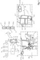
- Fig. 1 shows schematically the vehicle cabin 1 of an agricultural machine 2.
- the vehicle cabin 1 is assigned at least one mirror replacement system 3 according to the invention, the mirror replacement system 3 according to the invention comprising at least one visualization unit 4.
- the visualization unit 4 is coupled to a data processing unit 5, the data processing unit 5 providing image information X and parameter information Y generated by one or more camera systems 6 in a manner to be described in more detail.
- the visualization unit 4 is divided into two visualization areas 7, 8 in the illustrated exemplary embodiment, with each visualization area 7, 8 being assigned visualization content 9 provided by the data processing unit 5 and the visualization content 9 comprising the image information X and parameter information Y. It is within the scope of the invention that the visualization unit 4 comprises more than the two visualization areas 7, 8 shown.
- the visualization content 9 can also be edited.
- the visualization unit 4 can also be operated in operating modes 10.1 .. 10.n, with each visualization area 7, 8 of the visualization unit 4 visualizing a single operating mode 10.1 ..n or several operating modes 10.1 .. 10.n.
- the visualization device 4 can be designed as a left-hand or right-hand exterior mirror 11 and/or as an interior mirror 12.
- the visualization unit 4 designed as an exterior mirror 11 can be formed by a large number of visualization units 4.1 ... 4.4 and either as visualization units 4.3, 4.4 positioned inside the vehicle cabin 1 and / or as outside the vehicle cabin 1 positioned visualization units 4.1, 4.2 are executed.
- the following are shown in the exemplary embodiment Figure 1 only the right-side exterior mirrors 11 shown in the direction of travel FR are shown, with the left-side exterior mirrors 11, not shown, being designed in an analogous manner.
- the vehicle cabin 1 can be assigned a large number of visualization units 4.5, 4.6 designed as interior mirrors 12.
- the visualization unit 4.6 assigned to the front of the vehicle cabin 1 preferably fulfills the function of known rear-view mirrors 13.
- a visualization unit 4.5 designed as an interior mirror 12 can be assigned to the vehicle cabin 1 at any location. In the In the illustrated embodiment, a position of the visualization device 4.5 in the area of a side window 14 of the vehicle cabin 1 is shown as an example.
- a visualization unit 4 designed as an interior mirror 12 is positioned in an area of the agricultural work machine 2 that corresponds to the respective visualization content 9, so that the driver 15 of the agricultural work machine 2 intuitively assigns the respective visualized content 9 to an area of the agricultural work machine 2 can.
- the visualization unit 4.5 assigned to the right side window 14 as seen in the direction of travel FR can display visualization content 9 which is related to the right side of the agricultural machine 2 as seen in the direction of travel FR.
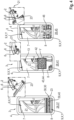
- Figure 2 shows a first embodiment variant of the mirror replacement system 3 according to the invention. Both illustrations in Figure 2 show the operation of the mirror replacement system 3 in an operating mode 10 "road” 16.
- the visualization unit 4 comprises at least two visualization areas 7, 8, one visualization area 8 having an area 17 around a ground engagement means 18, here a running wheel of a front axle 19 of the agricultural machine 2 visualized.
- the further visualization area 7 shows a rear area 21 of the agricultural machine 2, the visualization contents 9 of both visualization areas 7, 8 according to the invention comprising image information X and/or parameter information Y.
- the image information In the operating mode 10 shown, the parameter information Y also visualized includes at least one structural image 22 of an orientation of an attachment 23 adapted to the rear of the agricultural machine 2.
- the "road” operating mode 16 is also designed such that it includes a “straight drive” operating mode 24 and a “curving” operating mode 25, whereby in the “curving" operating mode 25 a viewing angle 26 is directed into the rear area 21 of the agricultural machine 2 Camera system 6 is larger than the viewing angle 27 of the same camera system 6 in the “straight journey” operating mode 24.
- the operating mode 10 of the visualization unit 4 includes a variety of “harvest” operating modes 28.
- the left representation of the Figure 3 shows the operation of the visualization unit 4 in a “Harvest 1” operating mode 29, wherein in the “Harvest 1” operating mode 29 the visualization unit 4 comprises at least two visualization areas 7, 8.
- One visualization area 8 visualizes an area 30 in the rear area of an attachment 23, here preferably a so-called harvesting header.
- the further visualization area 7 shows a rear area 21 of the agricultural machine 2, the visualization contents 9 of both visualization areas 7, 8 comprising image information X and/or parameter information Y and the image information rear area 21 of the agricultural machine 2, while the parameter information Y includes at least the display of the selected operating mode 29, here "Harvest 1".
- Such a structure has the effect that the mirror replacement system 3, in addition to the original rearview and side mirror function, also realizes a mirror function specifically aimed at the attachment, namely the visualization of the work quality of an attachment.
- An advantageous embodiment results in this context when the visualization content 9 of the visualization area 30 depicting the rear area 30 of the attachment 23 designed as a harvesting attachment is displayed in a larger visualization area 8 and the image section is rotated by 90 °.
- the middle representation of the Figure 3 shows the operation of the visualization unit 4 in a “Harvest 2” operating mode 31, wherein in the “Harvest 2” operating mode 31 the visualization unit 4 comprises at least two visualization areas 7, 8.
- One visualization area 8 visualizes an area 30 encompassing the crop edge 32.
- the further visualization area 7 shows a rear area 21 of the agricultural machine 2, the visualization contents 9 of both visualization areas 7, 8 comprising image information X and/or parameter information Y and the image information X from camera systems 6 are generated, which are directed in the direction of the crop edge 32 and in the direction of the rear area 21 of the agricultural machine 2 and the parameter information Y includes at least the display of the selected operating mode 31, here "Duck 2".
- This has the particular effect that the driver 15 of the agricultural machine 2 receives information about whether the attachment 23 is guided sufficiently precisely on the crop edge 32 so that he can take targeted countermeasures in the event of deviations.
- the right representation of the Figure 3 shows the operation of the visualization unit 4 in a “Harvest 3” operating mode 33, wherein in the “Harvest 3” operating mode 33 the visualization unit 4 comprises at least two visualization areas 7, 8.
- One visualization area 8 visualizes an area 30 encompassing the apron 34 of the agricultural working machine 2.
- the further visualization area 7 shows a rear area 21 of the agricultural working machine 2, the visualization contents 9 of both visualization areas 7, 8 comprising image information X and/or parameter information Y and the Image information is generated by camera systems 6, which are directed in the direction of the apron 34 of the agricultural machine 2 and in the direction of the rear area 21 of the agricultural machine 2 and the parameter information Y includes at least the display of target lanes 35 of the selected operating mode 33.
- the visualized target lanes 35 can be taken from a route planning system 36 that is known per se and is therefore not explained in more detail here.
- a route planning system 36 that is known per se and is therefore not explained in more detail here.
- Such a configuration has the effect that the driver 15 receives direct information from the mirror replacement system 3 as to whether his actual route corresponds to the originally planned route, so that he can intervene in the automated steering process in the event of significant deviations.
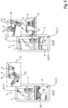
- FIG. 4 Left illustration shows the visualization unit 4 in a "Harvest 4" operating mode 37, wherein in the "Harvest 4" operating mode 37 the visualization unit 4 comprises at least two visualization areas 7, 8.
- One visualization area 8 visualizes an area 30 comprising the crop flow 38 in the attachment 23 designed as a harvesting header.
- the further visualization area 7 shows a rear area 21 of the agricultural machine 2, the visualization contents 9 of both visualization areas 7, 8 comprising image information X and/or parameter information Y and the image information
- the crop flow disruptions 39 are visualized by different colored bars 40, with red-marked bars 40 signaling a crop jam, while orange or yellow bars 40 signal a stagnant crop flow 38 and green bars 40 signal an undisturbed crop flow 38.
- Such a configuration has the particular effect that the mirror replacement system 3 provides the driver 15 with information about whether a jam in the attachment 23 is to be expected, so that the driver 15 can take suitable countermeasures, such as reducing the driving speed, in a timely manner.
- the middle representation in Figure 4 shows the operation of the visualization unit 4 in a “Harvest 5” operating mode 41, wherein in the “Harvest 5” operating mode 41 the visualization unit 4 comprises at least two visualization areas 7, 8.
- the contents of the visualization areas 7, 8 can be designed according to one or more of the “harvest” operating modes 28 already described. What is crucial is that in the “Harvest 5” operating mode 41, the visualization areas 7, 8 are overlaid by a visualization area 42 for visualizing parameter information Y.
- the visualization contents 9 of the visualization areas 7, 8 can include image information X and/or parameter information Y as already described.
- the image information Y includes at least the visualization of the crop stream 43 in the agricultural harvester 2, preferably the grain stream 44.
- mirror replacement system 3 This primarily has the effect that the mirror replacement system 3 generates additional information for the driver 23, which enables the driver 23 to assess the quality of work of the agricultural working machine 2 and enables him to specifically adjust parameter settings of the agricultural working machine 2 if necessary in order to do so to improve work quality.
- the right representation of the Figure 4 shows the operation of the visualization unit 4 in a “Harvest 6” operating mode 45, wherein in the “Harvest 6” operating mode 45 the visualization unit 4 comprises at least two visualization areas 7, 8.
- One visualization area 8 visualizes the crop stock 46 in an area 30 encompassing the apron 34 of the attachment 23 and the further visualization area 21 visualizes a rear area of the agricultural machine 2, the visualization contents 9 of both visualization areas 7, 8 comprising image information X and/or parameter information Y and the image information 6", includes.
- Figure 5 shows two further operating modes 10 of the mirror replacement system 3 according to the invention.
- the left representation of the Figure 5 shows the operation of the visualization unit 4 in an operating mode "attachment-uncoupling" 47, wherein in the "attachment-uncoupling" operating mode 47 the visualization unit 4 also includes at least two visualization areas 7, 8.
- One visualization area 8 visualizes an area 30 encompassing the coupling area 48 of the attachment 23.
- the further visualization area 7 shows a rear area 21 of the agricultural machine 2
- the visualization contents 9 of both visualization areas 7, 8 comprising image information X and/or parameter information Y and the image information are generated by camera systems 6 which are directed in the direction of an area 30 encompassing the coupling area 48 of the attachment 23 and in the direction of a rear area 21 of the agricultural machine 2 and the parameter information Y at least shows the display of the selected operating mode 10, here "intentional coupling-uncoupling" 47 include.
- the right representation of the Figure 5 shows the operation of the visualization unit 4 in an “overloading” operating mode 49, wherein in the “overloading” operating mode 49 the visualization unit 4 comprises at least two visualization areas 7, 8.
- One visualization area 8 visualizes an area 30 encompassing the unloading area 50 of a transport vehicle 51.
- the further visualization area 7 shows a rear area 21 of the agricultural machine 2
- the visualization contents 9 of both visualization areas 7, 8 comprising image information X and/or parameter information Y and the image information X of camera systems 6 are generated in the direction of an area 30 in the overload area 50 of a transport vehicle 51 and in the direction of the rear area 21 of agricultural work machines 2 and the parameter information Y at least includes the fading of the selected operating mode 10, here "overload" here whereby the upper illustration of the right illustration shows schematically the overloading 49 of an agricultural working machine 2 designed as a combine harvester and the lower illustration schematically shows the overloading 49 of an agricultural working machine 2 designed as a forage harvester.
- Figure 6 shows further operating modes 10 of the mirror replacement system 3 according to the invention.
- the left representation of the Figure 6 shows the operation of the visualization unit 4 in an operating mode 10 "reverse drive” 52, wherein in the "reverse drive” operating mode 52 the visualization unit 4 also comprises at least two visualization areas 7, 8, the visualization contents 9 of both visualization areas 7, 8 image information X and / or parameter information Y include.
- One visualization area 8 can include any structured visualization area 30, while the further visualization area 7 is structured in the manner of a rear-view mirror 13.
- the agricultural work machine 2 includes a plurality of camera systems 6, which are positioned on the agricultural work machine 2 in such a way that they record side areas 53 and rear areas 21 of the agricultural work machine 2.
- the image information X of these camera systems 6 are combined in such a way that the image information In this way, the visualization units 4 display images 54 of the environment 58 of the agricultural machine 2 in the manner of a wide-angle camera.
- the attachment 23 is coupled to the rear area of the combine harvester via a trailer eye 55 during road transport.
- the parameter information Y includes the display of the track image 56 of the towing eyelet 55.
- the right representation of the Figure 6 shows the operation of the visualization unit 4 in an "obstacle" operating mode 57, wherein in the "obstacle” operating mode 57 the visualization unit 4 comprises at least two visualization areas 7, 8, each of the visualization areas 7, 8 being areas 30, 21 in the environment 58 of the agricultural machine 2 includes. At least one visualization area 7 visualizes a rear area 21 in the manner of a rear-view mirror 13 and at least in this visualization area 7 parameter information Y is displayed, which visualize possible collision risks 59.
- the visualized risk of collision 59 can be the track image 60 of a transfer device 61 and/or obstacles 62 in the surroundings 58 of the agricultural machine 2, such as people, trees or telegraph poles. and/or a clearance height limit 63 and/or grain tank attachment limits 64.
- Figure 7 finally shows special positioning of the previously described camera systems 6 as well as the resulting special visualization content 9 of the visualization unit 4, which was also previously described in detail.
- the camera system 6 generating the image information X can be recorded by the attachment 23, so that the visualization unit 4 of the mirror replacement system 3 is set up Generate image information X when cornering.
- This visualization content 9 is particularly helpful when the agricultural machine 2 moves from a field onto the road or drives into an intersection area of a road, since the attachment 23 is often arranged far in front of the position of the driver 15, so that he can no longer see whether a dangerous situation arises in the area of the attachment 23.
- the camera system 6 that generates the image information This has the particular effect that the driver 15 receives information about road users 67, such as cyclists, and traffic situations in advance 34 of the agricultural machine 2 from the mirror replacement system 3 when turning 66, which he cannot see himself.
- the visualization unit 4 of the mirror replacement system 3 can be set up to combine the image information X generated by the respective camera system 6 with person recognition 68, so that people 68 are made particularly identifiable in the respective visualization unit 4.
- the visualization unit 4 is set up to combine the image information X generated by the respective camera system 6 with night vision effects 69. This improves the detection of living beings (people 68 or animals) in the dark.
- the visualization unit 4 can also be set up to derive the image information ⁇ b>Reference symbol list: ⁇ /b> 1 Vehicle cabin 34 Apron 2 agricultural working machine 35 Target lane 3 Mirror replacement system 36 Route planning system 4 Visualization unit 37 “Harvest 4” operating mode 5 Data processing unit 38 Good flow 6 Camera system 39 Crop flow disruption 7 Visualization area 40 bar 8th Visualization area 41 “Harvest 5” operating mode 9 Visualization content 42 Visualization area 10 operation mode 43 Gutstrom 11 Exterior mirror 44 grain stream 12 Interior mirror 45 “Harvest 6” operating mode 13 Rear view mirror 46 Crop inventory 14 Side window 47 BM “Coupling-uncoupling intention” 15 driver 48 Coupling area 16 “Road” operating mode 49 Operating mode "Overloaded 17 Area 50 Overloading area 18 Ground intervention means 51 transport vehicle 19 Front axle 52 “Reverse travel” operating mode 20 Floor 53 Lateral area 21 rear area 54 Ready-made image 22 Structural image 55 Attachment eye 23 Attachment 56 Track image 24 Operating mode “straight travel” 57 “Obstacle” operating mode 25 “Curving” operating
Landscapes
- Engineering & Computer Science (AREA)
- Mechanical Engineering (AREA)
- Life Sciences & Earth Sciences (AREA)
- Multimedia (AREA)
- Soil Sciences (AREA)
- Environmental Sciences (AREA)
- Guiding Agricultural Machines (AREA)
Applications Claiming Priority (1)
| Application Number | Priority Date | Filing Date | Title |
|---|---|---|---|
| DE102022108925.8A DE102022108925A1 (de) | 2022-04-12 | 2022-04-12 | Spiegelersatzsystem und landwirtschaftliche Arbeitsmaschine mit Spiegelersatzsystem |
Publications (1)
| Publication Number | Publication Date |
|---|---|
| EP4261083A1 true EP4261083A1 (fr) | 2023-10-18 |
Family
ID=85222513
Family Applications (1)
| Application Number | Title | Priority Date | Filing Date |
|---|---|---|---|
| EP23155793.5A Pending EP4261083A1 (fr) | 2022-04-12 | 2023-02-09 | Système de remplacement de miroir et machine de travail agricole dotée d'un système de remplacement de miroir |
Country Status (2)
| Country | Link |
|---|---|
| EP (1) | EP4261083A1 (fr) |
| DE (1) | DE102022108925A1 (fr) |
Families Citing this family (2)
| Publication number | Priority date | Publication date | Assignee | Title |
|---|---|---|---|---|
| DE102023129910A1 (de) | 2023-10-30 | 2025-04-30 | Claas Kommanditgesellschaft auf Aktien mbH | Fahrzeugkabine mit einer Visualisierungseinrichtung, landwirtschaftliche Arbeitsmaschine und Verfahren |
| DE102024118043A1 (de) | 2024-06-26 | 2025-12-31 | Claas Selbstfahrende Erntemaschinen Gmbh | Landwirtschaftliche Arbeitsmaschine und Verfahren |
Citations (7)
| Publication number | Priority date | Publication date | Assignee | Title |
|---|---|---|---|---|
| US20140240506A1 (en) * | 2013-02-22 | 2014-08-28 | Caterpillar Inc. | Display System Layout for Remote Monitoring of Machines |
| DE112014001482T5 (de) * | 2013-03-15 | 2015-12-17 | Topcon Positioning Systems, Inc. | Überwachungs- und Steueranzeigesystem und -verfahren |
| EP2743132B1 (fr) | 2012-12-13 | 2017-08-02 | CLAAS Tractor S.A.S. | Système de support de vision du conducteur |
| DE102017206977A1 (de) | 2017-04-26 | 2018-10-31 | Continental Automotive Gmbh | Vorrichtung und Verfahren zur Steuerung einer Spiegelersatz-Kamera |
| EP3437929A1 (fr) * | 2017-07-31 | 2019-02-06 | MEKRA Lang GmbH & Co. KG | Système de vision à champs de vision / effet d'incrustation de la zone de vision en fonction de la situation de conduite |
| EP3401167B1 (fr) | 2015-09-02 | 2020-01-29 | MAN Truck & Bus SE | Système de remplacement de rétroviseur en tant que système de surveillance par cémera d'un véhicule automobile, en particulier d'un véhicule utilitaire |
| EP3970466A1 (fr) * | 2020-09-17 | 2022-03-23 | Deere & Company | Système et procédé permettant de présenter l'environnement d'un outil agricole |
-
2022
- 2022-04-12 DE DE102022108925.8A patent/DE102022108925A1/de active Pending
-
2023
- 2023-02-09 EP EP23155793.5A patent/EP4261083A1/fr active Pending
Patent Citations (7)
| Publication number | Priority date | Publication date | Assignee | Title |
|---|---|---|---|---|
| EP2743132B1 (fr) | 2012-12-13 | 2017-08-02 | CLAAS Tractor S.A.S. | Système de support de vision du conducteur |
| US20140240506A1 (en) * | 2013-02-22 | 2014-08-28 | Caterpillar Inc. | Display System Layout for Remote Monitoring of Machines |
| DE112014001482T5 (de) * | 2013-03-15 | 2015-12-17 | Topcon Positioning Systems, Inc. | Überwachungs- und Steueranzeigesystem und -verfahren |
| EP3401167B1 (fr) | 2015-09-02 | 2020-01-29 | MAN Truck & Bus SE | Système de remplacement de rétroviseur en tant que système de surveillance par cémera d'un véhicule automobile, en particulier d'un véhicule utilitaire |
| DE102017206977A1 (de) | 2017-04-26 | 2018-10-31 | Continental Automotive Gmbh | Vorrichtung und Verfahren zur Steuerung einer Spiegelersatz-Kamera |
| EP3437929A1 (fr) * | 2017-07-31 | 2019-02-06 | MEKRA Lang GmbH & Co. KG | Système de vision à champs de vision / effet d'incrustation de la zone de vision en fonction de la situation de conduite |
| EP3970466A1 (fr) * | 2020-09-17 | 2022-03-23 | Deere & Company | Système et procédé permettant de présenter l'environnement d'un outil agricole |
Also Published As
| Publication number | Publication date |
|---|---|
| DE102022108925A1 (de) | 2023-10-12 |
Similar Documents
| Publication | Publication Date | Title |
|---|---|---|
| EP3219533B1 (fr) | Système de vision pour un véhicule, notamment pour un véhicule utilitaire | |
| EP1674324B2 (fr) | Machine de travail agricole | |
| EP0843960B1 (fr) | Dispositif pour contrôler le transbordement de marchandises d'une machine de travail à un véhicule de transport | |
| EP3254902B1 (fr) | Dispositif de surveillance de l'environnement d'un véhicule automobile, son procédé de fonctionnement et véhicule automobile en étant équipé | |
| EP3437929B1 (fr) | Système de vision à champs de vision / effet d'incrustation de la zone de vision en fonction de la situation de conduite | |
| EP3227826B1 (fr) | Procédé de détermination d'un champ d'angle mort spécifique au conducteur pour un système d'assistance au conducteur, système d'assistance au conducteur et véhicule automobile | |
| EP0503350B1 (fr) | Véhicule de travail | |
| EP4261083A1 (fr) | Système de remplacement de miroir et machine de travail agricole dotée d'un système de remplacement de miroir | |
| DE202012103730U1 (de) | Erntemaschine mit einer Überladeeinrichtung | |
| DE10303380A1 (de) | Erntemaschine zum Ernten von stängelartigem Erntegut wie Mais oder dergleichen | |
| EP2821322B1 (fr) | Véhicule doté de plusieurs programmes de direction | |
| DE102008023504A1 (de) | Streckenüberwachungssystem für ein Fahrzeug und Verfahren zu dessen Betrieb | |
| DE102016115313A1 (de) | Verfahren zum Unterstützen eines Fahrers eines Gespanns, Fahrerassistenzsystem sowie Gespann | |
| EP4261084A1 (fr) | Système de remplacement de miroir et machine de travail agricole dotée d'un système de remplacement de miroir | |
| EP3794927B1 (fr) | Machine de travail agricole | |
| EP1894462A1 (fr) | Convoyeur agricole | |
| EP4553770A1 (fr) | Système basé sur une caméra et procédé de détermination de la position d'une remorque | |
| EP3369697B1 (fr) | Chariot de manutention | |
| EP4197308B1 (fr) | Broyeur auxiliaire et train de travail doté d'un broyeur auxiliaire | |
| EP0882643A1 (fr) | Réglage de position du siège pour machine de récolte agricole | |
| EP4549216A1 (fr) | Cabine de véhicule dotée d'un dispositif de visualisation, machine de travail agricole et procédé | |
| EP4449849B1 (fr) | Système pour éviter une collision entre une moissonneuse agricole et un véhicule d'accompagnement | |
| EP4552455A1 (fr) | Système de planification d'itinéraire de machines agricoles autonomes | |
| DE102021118273A1 (de) | Landwirtschaftliche Arbeitsmaschine | |
| EP4268561A1 (fr) | Ensemble machine de travail agricole et machine de travail associée |
Legal Events
| Date | Code | Title | Description |
|---|---|---|---|
| PUAI | Public reference made under article 153(3) epc to a published international application that has entered the european phase |
Free format text: ORIGINAL CODE: 0009012 |
|
| STAA | Information on the status of an ep patent application or granted ep patent |
Free format text: STATUS: THE APPLICATION HAS BEEN PUBLISHED |
|
| AK | Designated contracting states |
Kind code of ref document: A1 Designated state(s): AL AT BE BG CH CY CZ DE DK EE ES FI FR GB GR HR HU IE IS IT LI LT LU LV MC ME MK MT NL NO PL PT RO RS SE SI SK SM TR |
|
| P01 | Opt-out of the competence of the unified patent court (upc) registered |
Effective date: 20231018 |
|
| STAA | Information on the status of an ep patent application or granted ep patent |
Free format text: STATUS: REQUEST FOR EXAMINATION WAS MADE |
|
| 17P | Request for examination filed |
Effective date: 20240418 |
|
| RBV | Designated contracting states (corrected) |
Designated state(s): AL AT BE BG CH CY CZ DE DK EE ES FI FR GB GR HR HU IE IS IT LI LT LU LV MC ME MK MT NL NO PL PT RO RS SE SI SK SM TR |
|
| STAA | Information on the status of an ep patent application or granted ep patent |
Free format text: STATUS: EXAMINATION IS IN PROGRESS |
|
| 17Q | First examination report despatched |
Effective date: 20250523 |