EP1297596B1 - Garniture de raccordement pourvue d'une bague elastique comme butee - Google Patents
Garniture de raccordement pourvue d'une bague elastique comme butee Download PDFInfo
- Publication number
- EP1297596B1 EP1297596B1 EP01951513A EP01951513A EP1297596B1 EP 1297596 B1 EP1297596 B1 EP 1297596B1 EP 01951513 A EP01951513 A EP 01951513A EP 01951513 A EP01951513 A EP 01951513A EP 1297596 B1 EP1297596 B1 EP 1297596B1
- Authority
- EP
- European Patent Office
- Prior art keywords
- connecting fitting
- sloping surface
- opening
- ring
- axial direction
- Prior art date
- Legal status (The legal status is an assumption and is not a legal conclusion. Google has not performed a legal analysis and makes no representation as to the accuracy of the status listed.)
- Expired - Lifetime
Links
Images

Classifications
-
- H—ELECTRICITY
- H02—GENERATION; CONVERSION OR DISTRIBUTION OF ELECTRIC POWER
- H02G—INSTALLATION OF ELECTRIC CABLES OR LINES, OR OF COMBINED OPTICAL AND ELECTRIC CABLES OR LINES
- H02G15/00—Cable fittings
- H02G15/02—Cable terminations
- H02G15/04—Cable-end sealings
-
- F—MECHANICAL ENGINEERING; LIGHTING; HEATING; WEAPONS; BLASTING
- F16—ENGINEERING ELEMENTS AND UNITS; GENERAL MEASURES FOR PRODUCING AND MAINTAINING EFFECTIVE FUNCTIONING OF MACHINES OR INSTALLATIONS; THERMAL INSULATION IN GENERAL
- F16L—PIPES; JOINTS OR FITTINGS FOR PIPES; SUPPORTS FOR PIPES, CABLES OR PROTECTIVE TUBING; MEANS FOR THERMAL INSULATION IN GENERAL
- F16L41/00—Branching pipes; Joining pipes to walls
- F16L41/08—Joining pipes to walls or pipes, the joined pipe axis being perpendicular to the plane of a wall or to the axis of another pipe
- F16L41/14—Joining pipes to walls or pipes, the joined pipe axis being perpendicular to the plane of a wall or to the axis of another pipe by screwing an intermediate part against the inside or outside of the wall
Definitions
- connection fitting for fastening elongate bodies, for example of hoses, corrugated tubes, pipes, cables or the like, at an opening, in particular at an opening or a perforation, for example in a wall of a housing or the like, wherein the connection fitting in the insertion direction axially projecting fastening projection which is divided by substantially axially extending slots in retaining tongues, on the outside at least in the use position about radially outwardly projecting retaining projections are arranged, wherein the retaining tongues during insertion of the fastening projection in the opening, the opening or the like perforation behind the edge of the opening into the holding position, in which they at least partially engage behind this edge, at a distance from the holding projections at least one stop is arranged, which in the position of use on the hinterg Riffenen edge of the opening opposite the opening edge is applied and the stopper is an elastic or rubber-elastic ring which supported on an obliquely from the inside outwardly widening away from
- connection fitting is from the German patent DE 198 04 719 C1 known and has proven itself, because it can be attached to openings, perforations or openings of housing walls with different wall thicknesses, wherein the elasticity of the stop forming ring is utilized to compensate for different wall thicknesses, as this ring on one of the opening away expanding surface of the Connection fitting is supported and can be moved more or less far under elastic enlargement of its diameter depending on the wall thickness.
- an elastic ring with a relatively large cross-section must be used to take into account relatively thin wall thicknesses, which makes greater deformation forces required when used on relatively thick wall thicknesses.
- an elastic ring with a larger cross-section also means higher costs.
- connection fitting of the type defined with which in their respective cross-section smaller rings can be used as attacks and yet larger wall thicknesses can be detected.
- connection fitting adjacent to the oblique surface having area and / or divided in the region of the largest diameter of the inclined surface and the inclined surface having separate part of the connection fitting in the axial direction adjustable and thereby the axial distance of the inclined surface of the retaining projections is changeable or preselected.
- this elastic ring for example, an O-ring, be.
- this elastic ring for example, an O-ring.
- the oblique surface having separate part by means of a thread by rotation in the axial direction is adjustable and in particular fixable.
- a continuous adjustment can be made to different wall thicknesses.
- the self-locking of the thread in particular in cooperation with the elastic ring or O-ring.
- the inclined surface having part may be a ring which has at least over part of its axial extent an internal thread which fits on an external thread on the connection fitting.
- the part having the inclined surface may have an annular region adjacent to the oblique surface in the axial direction, in the position of use of the holding projections further than the inclined surface arranged, which formed as a gripping ring for twisting and / or with deformations for detecting by hand or optionally by means of a Tool is provided. So it is particularly favorable for ease of use, when the oblique surface having area with some distance from the end of the inclined surface, ie the area with the largest diameter is divided with respect to the connection fitting, so that at the same time a gripping ring is formed, which is a comfortable Detecting and screwing the oblique surface having part or Ringes allowed.
- a modified embodiment may consist in that the oblique surface having part or ring is axially adjustable in stages and by means of a releasable locking, for example, with at least one in Querlochept of the part or ring and the connection fitting matching cross pin can be fixed. Since the serving as a stop elastic ring wall thickness differences can compensate for the perforation of the housing, sudden or gradual adjustments and definitions of the inclined surface having separate part may be sufficient to compensate for large differences in wall thickness easily. It can then be avoided the attachment of threads.
- the cross pin may be formed as a screw, whereby it is secured accordingly well even in its locked position.
- the number of transverse perforations depends on which thickness differences of the wall thickness in the region of a housing breakthrough should be bridged.
- connection fitting for the sake of completeness it should be mentioned that a further thread for a screw can be provided on the connection fitting, whereby a arranged within the connection fitting collet with clamping fingers for fixing, for example, a cable can be operated in a conventional manner.
- parts which correspond to one another in terms of their function receive matching reference numbers, even with a modified shape or design.
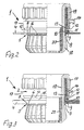
- a generally designated 1 connection fitting is used for fixing elongated bodies, in the embodiment for attaching a substantially smooth outside body, such as a cable, to an opening 3, for example at an opening or a hole in a wall 4, for example a housing or similar.
- a substantially smooth outside body such as a cable
- the elongated body or the cable are not shown for the sake of clarity.
- connection fitting 1 in this case has an axially protruding in the insertion direction indicated by the arrow PF1 in Fig.1 mounting projection 5, which is divided by substantially axially extending slots 6 in retaining tongues 7, arranged on the outside radially projecting retaining projections 8 are, upon insertion of the fastening projection 5 and thus the retaining tongue 7 in the opening 3 according to Figure 2 to 5 behind the edge 9 in its holding position, in which the retaining projections 8 engage behind this edge 9. They have an approximately sawtooth-like cross-section, that is, counter to the insertion gradually increases its height to its largest radial dimension, then drop relatively steep or lying in a radial plane, said steep drop with the Lochungsrand 9 in use position in operative connection is.
- a stop described in more detail below is arranged, which abuts in the position of use on the rear edge behind the opening 9 3 opposite opening edge 10, as shown in Figures 2 to 5.
- the abovementioned stop is in this case according to FIGS. 2 to 5, as far as the direct contact with the opening edge 10 is concerned, a rubber-elastic ring 11, preferably an O-ring, which is supported on an obliquely from the inside to the outside obliquely away from the opening 3 surface 12.
- the stop is thus formed in total by this inclined surface 12 and the elastic ring 11 adjacent thereto.
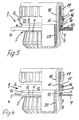
- connection fitting 1 is adjacent to the inclined surface 12th divided portion having and the inclined surface 12 having, separate part 2 is adjustable to the connection fitting 1 in the axial direction, as the comparison of each of Figures 2 and 3 or 4 and 5 clearly shows. Consequently the axial distance of the inclined surface 12 or its beginning of the retaining projections 8 can be changed and preselected, that is, it can be made from the outset a rough adaptation to the respective wall thickness, so that the elastic stop ring 11 then only a small deformation must be subjected to effect the exact adaptation to the respective wall thickness.
- the oblique surface 12 having part 2 by means of a thread by twisting in the axial direction adjustable and by the self-locking of this thread and the friction on the elastic ring 11 can be fixed.
- the oblique surface 1 2 having part 2 is a ring which has a portion of its axial extent an internal thread 13 which fits on an external thread 14 on the connection fitting 1 in the region of mutual separation surface.
- this part 2 is screwed in the axial direction into its upper end position, ie the position farthest from the retaining projections 8, while FIG. 2 shows a screwing in the opposite direction with a corresponding reduction in the distance to the retaining projections 8. In this position according to Figure 2 so a part of the internal thread of the annular part 2 has the Leave external thread 14 of the connection fitting 1.
- the oblique surface 12 having part 2 is axially adjustable in stages and by means of a releasable locking, namely with at least one transverse holes 15 of the part 2 and the Anschlußaramtur 1 matching cross pin 16 can be fixed, which optionally also as a screw can be trained to be self-assured.
- a releasable locking namely with at least one transverse holes 15 of the part 2 and the Anschlußaramtur 1 matching cross pin 16 can be fixed, which optionally also as a screw can be trained to be self-assured.
- the transverse perforations 15 for the transverse pin 16 are arranged in this annular region 17.
- connection fitting 1 her in this case associated Collet 18, which can be tightened by means of a threaded sleeve 19 in the axial direction to press a seal 20 against an elongated body to be determined and to clamp even in the field of connection fitting.
- connection fitting 1 for fixing elongated bodies to perforations or openings 3, in particular a wall 4 of a housing has on the one hand the edge 9 of this hole 3 engaging behind retaining projections 8 and on the other hand designed as an elastic ring 11 stop which in the position of use at the behind the engaged edge. 9 the opening 3 opposite opening edge 10 is present.
- This elastic ring 11 is supported on an obliquely from the inside to the outside of the opening 3 away surface 12 of the connection fitting 1, so that it is axially movable and displaceable under elastic enlargement of its diameter to take into account different wall thicknesses.
- connection fitting 1 adjacent to the oblique surface 12 having portion is divided and the inclined surface 12 having separate part 2 is adjustable to the connection fitting 1 in the axial direction, whereby the axial distance of the inclined surface 12th can be changed or pre-selected by the retaining projections 8 and thereby at least roughly adaptable to different wall thicknesses.
Landscapes
- General Engineering & Computer Science (AREA)
- Engineering & Computer Science (AREA)
- Mechanical Engineering (AREA)
- Clamps And Clips (AREA)
- Quick-Acting Or Multi-Walled Pipe Joints (AREA)
- Telephone Set Structure (AREA)
- Forms Removed On Construction Sites Or Auxiliary Members Thereof (AREA)
- Adornments (AREA)
- Dowels (AREA)
- Mutual Connection Of Rods And Tubes (AREA)
- Mirrors, Picture Frames, Photograph Stands, And Related Fastening Devices (AREA)
- Snaps, Bayonet Connections, Set Pins, And Snap Rings (AREA)
- Vibration Dampers (AREA)
- Springs (AREA)
- Hooks, Suction Cups, And Attachment By Adhesive Means (AREA)
- Insertion Pins And Rivets (AREA)
- Connection Of Plates (AREA)
Claims (8)
- Garniture de raccordement (1) pour fixer des corps oblongs, par exemple des tuyaux souples, des tuyaux souples ondulés, des tuyaux, des câbles ou analogues, au niveau d'une ouverture (3), notamment d'un passage ou d'un trou par exemple dans une paroi (4) d'un boîtier ou analogues, la garniture de raccordement (1) présentant une saillie de fixation (5) faisant saillie axialement dans la direction d'enfoncement (Pfl), qui est divisée par des fentes (6) s'étendant essentiellement dans la direction axiale en languettes de retenue (7) sur l'extérieur desquelles sont disposées des saillies de retenue (8) faisant saillie radialement vers l'extérieur au moins en position d'utilisation, sachant que, lorsque l'on introduit la saillie de fixation (5) dans l'ouverture (3), dans le passage ou dans un trou similaire, les languettes de retenue (7) viennent se mettre en position de retenue derrière le bord (9) de l'ouverture (3), position dans laquelle elles sont au moins partiellement enclenchées derrière ledit bord (9), au moins une butée étant disposée à distance des saillies de retenue (8), qui, en position d'utilisation, est appliquée contre le bord (10) de l'ouverture opposé au bord (9) de l'ouverture (3) derrière lequel sont enclenchées les languettes de retenue, et la butée étant une bague (11) élastique ou présentant une élasticité caoutchoutique prenant appui sur une surface (12) de la garniture de raccordement (1), qui s'élargit en biais de l'intérieur vers l'extérieur en partant de l'ouverture, et étant mobile ou déplaçable dans la direction axiale sur ladite surface oblique (12) en augmentant élastiquement son diamètre contre sa force de rappel élastique, caractérisée en ce que la garniture de raccordement (1) est divisée à proximité de la zone présentant la surface oblique (12) et/ou dans la zone du plus grand diamètre de la surface oblique (12), et en ce que la partie divisée (2) présentant la surface oblique (12) peut être déplacée axialement sur la garniture de raccordement (1), permettant ainsi de modifier ou de présélectionner l'éloignement axial de la surface oblique (12) des saillies de retenue (8).
- Garniture de raccordement selon la revendication 1, caractérisée en ce que la partie (2) présentant la surface oblique (12) peut être déplacée dans la direction axiale et notamment immobilisée au moyen d'un filetage, en la faisant tourner.
- Garniture de raccordement selon la revendication 1 ou 2, caractérisée en ce que la partie (2) présentant la surface oblique (12) est une bague qui présente sur au moins une partie de son étendue axiale un taraudage (13) adapté à un filetage extérieur (14) de la garniture de raccordement (1).
- Garniture de raccordement selon l'une des revendications 1 à 3, caractérisée en ce que la partie (2) présentant la surface oblique (12) comporte une zone annulaire (17) adjacente à la surface oblique (12) dans la direction axiale qui, en position d'utilisation, est davantage éloignée des saillies de retenue (8) que la surface oblique (12), laquelle zone est réalisée en tant que bague de préhension pour tourner et/ou est dotée d'un relief permettant de la saisir avec la main ou, le cas échéant, au moyen d'un outil.
- Garniture de raccordement selon la revendication 1, caractérisée en ce que la partie (2) présentant la surface oblique (12) peut être déplacée axialement de façon graduelle et immobilisée au moyen d'un dispositif de verrouillage amovible, par exemple au moyen d'au moins une tige transversale (16) associée à des trous transversaux (15) de la partie (2) et de la garniture de raccordement (1).
- Garniture de raccordement selon la revendication 1 ou 5, caractérisée en ce que plusieurs trous transversaux (15) sont prévus axialement sur la garniture de raccordement et un trou transversal est prévu sur la partie (2).
- Garniture de raccordement selon l'une des revendications 1, 5 ou 6, caractérisée en ce que la tige transversale (16) est réalisée en tant que vis.
- Garniture de raccordement selon l'une des revendications 1 ou 5 à 7, caractérisée en ce que la partie (2) présentant la surface oblique (12) comporte une zone annulaire (17) adjacente à la surface oblique (12) dans la direction axiale, qui, en position d'utilisation, est davantage éloignée des saillies de retenue (8) que la surface oblique (12), et sur laquelle est disposé le trou transversal (15) pour la tige transversale (16).
Applications Claiming Priority (3)
| Application Number | Priority Date | Filing Date | Title |
|---|---|---|---|
| DE10032010 | 2000-07-01 | ||
| DE10032010A DE10032010C1 (de) | 2000-07-01 | 2000-07-01 | Anschlußarmatur mit elastischem Ring als Anschlag |
| PCT/EP2001/005909 WO2002003520A1 (fr) | 2000-07-01 | 2001-05-23 | Garniture de raccordement pourvue d"une bague elastique comme butee |
Publications (2)
| Publication Number | Publication Date |
|---|---|
| EP1297596A1 EP1297596A1 (fr) | 2003-04-02 |
| EP1297596B1 true EP1297596B1 (fr) | 2007-12-26 |
Family
ID=7647423
Family Applications (1)
| Application Number | Title | Priority Date | Filing Date |
|---|---|---|---|
| EP01951513A Expired - Lifetime EP1297596B1 (fr) | 2000-07-01 | 2001-05-23 | Garniture de raccordement pourvue d'une bague elastique comme butee |
Country Status (10)
| Country | Link |
|---|---|
| US (1) | US6722704B2 (fr) |
| EP (1) | EP1297596B1 (fr) |
| CN (1) | CN1303735C (fr) |
| AT (1) | ATE382199T1 (fr) |
| AU (1) | AU2001272416A1 (fr) |
| BR (1) | BR0111725A (fr) |
| DE (2) | DE10032010C1 (fr) |
| EA (1) | EA003684B1 (fr) |
| ES (1) | ES2298242T3 (fr) |
| WO (1) | WO2002003520A1 (fr) |
Families Citing this family (25)
| Publication number | Priority date | Publication date | Assignee | Title |
|---|---|---|---|---|
| DE10152331B4 (de) * | 2001-10-26 | 2011-02-17 | Murrplastik Systemtechnik Gmbh | Schlauchfassung |
| DE20211347U1 (de) * | 2002-07-27 | 2002-09-26 | Anton Hummel Verwaltungs Gmbh, 79183 Waldkirch | Anschlussarmatur |
| US7004844B2 (en) * | 2003-10-03 | 2006-02-28 | Timken Us Corporation | Clearance damping device for a telescoping shaft assembly |
| US7832773B2 (en) * | 2006-09-18 | 2010-11-16 | Krohn Kenneth P | Adjustable connector and method for its use |
| DE202007003957U1 (de) | 2007-03-19 | 2008-07-31 | Anton Hummel Verwaltungs-Gmbh | Kabelverschraubung mit Schraubhülse und Überwurfmutter |
| US7963567B2 (en) * | 2007-04-27 | 2011-06-21 | Securus, Inc. | Anti-rotation pipe locator and holder |
| US8109539B2 (en) * | 2007-07-17 | 2012-02-07 | Krohn Kenneth P | Variable joining device and method for its use |
| DE202007017765U1 (de) * | 2007-12-20 | 2008-03-06 | Anton Hummel Verwaltungs-Gmbh | Anschlussarmatur |
| US20090208271A1 (en) * | 2008-02-19 | 2009-08-20 | Krohn Kenneth P | Modular coupling system |
| US20090218808A1 (en) * | 2008-03-01 | 2009-09-03 | Krohn Kenneth P | Improved duct coupling system |
| US20090230678A1 (en) * | 2008-03-14 | 2009-09-17 | Krohn Kenneth P | Compression fitting adjustment system |
| US20100019484A1 (en) * | 2008-07-23 | 2010-01-28 | Krohn Kenneth P | Compression fitting adjustment system |
| US20100133810A1 (en) * | 2008-11-29 | 2010-06-03 | Krohn Kenneth P | Device for connecting to ducts of various sizes and shapes |
| US20100283237A1 (en) * | 2009-01-24 | 2010-11-11 | Krohn Kenneth P | Device for connecting to ducts of various sizes and shapes |
| DE102009021700A1 (de) | 2009-05-17 | 2010-11-18 | Hidde, Axel, Dipl.-Ing. | Universal- Schnellverschraubung |
| DE102009059327A1 (de) * | 2009-12-30 | 2011-07-07 | Franz Schneider Brakel GmbH & Co. KG, 33034 | Beschlag für Türen oder Fenster |
| PL398573A1 (pl) * | 2012-03-22 | 2013-09-30 | Aic Spólka Akcyjna | Króciec podlaczeniowy wymiennika ciepla |
| WO2014067352A1 (fr) * | 2012-10-31 | 2014-05-08 | 李飞宇 | Ensemble de raccordement étanche à installation rapide |
| EP2927551B1 (fr) * | 2014-03-31 | 2022-03-02 | Uponor Innovation AB | Manchon de raccordement et boîtier de collecteur |
| US10094503B2 (en) * | 2016-01-20 | 2018-10-09 | Brian John Kelk | Sewer pipe fitting assembly |
| CN106684774B (zh) * | 2017-02-27 | 2018-03-20 | 长沙南车电气设备有限公司 | 一种波纹管用适配器 |
| WO2020041505A1 (fr) * | 2018-08-21 | 2020-02-27 | Jess Briley Manufacturing Company | Ensemble tubulaire et procédé de raccordement d'éléments tubulaires |
| CN110735984B (zh) * | 2019-10-24 | 2021-02-12 | 江苏宏博机械制造有限公司 | 一种便于安装的高密封性波纹管连接装置 |
| US20240044433A1 (en) * | 2022-08-05 | 2024-02-08 | Inno Workz, LLC | Blind bulkhead fitting |
| JP1734991S (ja) * | 2022-08-08 | 2023-01-19 | 管継手用スリーブ |
Family Cites Families (15)
| Publication number | Priority date | Publication date | Assignee | Title |
|---|---|---|---|---|
| US2472569A (en) * | 1946-01-26 | 1949-06-07 | Caldwell Percy Graham | Means for securing a pipe fitting to a plate, wall, or the like |
| US2759743A (en) * | 1949-01-21 | 1956-08-21 | Douglas Aircraft Co Inc | High tolerance sealed jointure for hydraulic connections |
| US3003795A (en) * | 1959-08-12 | 1961-10-10 | L & L Mfg Company | Tube coupling having a resilient metal sealing sleeve |
| US3139768A (en) * | 1961-12-11 | 1964-07-07 | Illinois Tool Works | Cable fastener assembly |
| US3275348A (en) * | 1963-05-28 | 1966-09-27 | Vsi Corp | High pressure sealed connections |
| US4150836A (en) * | 1977-02-16 | 1979-04-24 | Mcdonnell Douglas Corporation | Backed boss seal fitting |
| CH640617A5 (de) * | 1979-07-06 | 1984-01-13 | Baumgartner Merzia | Verbindungselement zum einschrauben in eine leitung oder in einen apparat zum anschluss an das leitungssystem des druckmediumkreislaufes. |
| US4570983A (en) * | 1983-03-15 | 1986-02-18 | Arla | Pipe connection with a seal ring satisfying hygienic demands |
| DE4325420C2 (de) | 1993-07-29 | 1998-10-08 | Nuesse Octavio K | Kabeldurchgangsvorrichtung zur Durchführung eines ummantelten Kabels durch eine Wandperforation |
| EP0790453A3 (fr) | 1996-02-19 | 1997-11-26 | Hauff-Technik GmbH & Co. KG | Traversée de câble/tuyaux pour une ouverture dans un mur |
| DE19804719C1 (de) | 1998-02-06 | 1999-04-08 | Hummel Anton Verwaltung | Anschlußarmatur mit axial vorstehendem Befestigungsvorsprung |
| DE19812079C1 (de) * | 1998-03-19 | 1999-04-15 | Hummel Anton Verwaltung | Anschlußarmatur mit einem Befestigungsvorsprung |
| DE19825989C1 (de) * | 1998-06-10 | 1999-11-18 | Hummel Anton Verwaltung | Winkelförmige Leitungseinführung mit einer Trennstelle zwischen den beiden Schenkeln |
| DE19828059C2 (de) * | 1998-06-24 | 2001-04-26 | Hummel Anton Verwaltung | Anschlußarmatur mit einem durch Schlitze in Haltezungen aufgeteilten Befestigungsvorsprung |
| DE10033911C1 (de) * | 2000-07-12 | 2002-04-04 | Hummel Anton Verwaltung | Anschlussarmatur für längliche Körper mit Spannzange |
-
2000
- 2000-07-01 DE DE10032010A patent/DE10032010C1/de not_active Expired - Fee Related
-
2001
- 2001-05-12 US US10/258,981 patent/US6722704B2/en not_active Expired - Fee Related
- 2001-05-23 ES ES01951513T patent/ES2298242T3/es not_active Expired - Lifetime
- 2001-05-23 EA EA200201166A patent/EA003684B1/ru not_active IP Right Cessation
- 2001-05-23 DE DE50113418T patent/DE50113418D1/de not_active Expired - Lifetime
- 2001-05-23 EP EP01951513A patent/EP1297596B1/fr not_active Expired - Lifetime
- 2001-05-23 AU AU2001272416A patent/AU2001272416A1/en not_active Abandoned
- 2001-05-23 BR BR0111725-4A patent/BR0111725A/pt not_active IP Right Cessation
- 2001-05-23 AT AT01951513T patent/ATE382199T1/de not_active IP Right Cessation
- 2001-05-23 WO PCT/EP2001/005909 patent/WO2002003520A1/fr not_active Ceased
- 2001-05-23 CN CNB018085466A patent/CN1303735C/zh not_active Expired - Fee Related
Also Published As
| Publication number | Publication date |
|---|---|
| BR0111725A (pt) | 2003-05-27 |
| WO2002003520A1 (fr) | 2002-01-10 |
| CN1426619A (zh) | 2003-06-25 |
| DE10032010C1 (de) | 2001-09-13 |
| ATE382199T1 (de) | 2008-01-15 |
| US6722704B2 (en) | 2004-04-20 |
| DE50113418D1 (de) | 2008-02-07 |
| EP1297596A1 (fr) | 2003-04-02 |
| AU2001272416A1 (en) | 2002-01-14 |
| EA200201166A1 (ru) | 2003-04-24 |
| ES2298242T3 (es) | 2008-05-16 |
| EA003684B1 (ru) | 2003-08-28 |
| CN1303735C (zh) | 2007-03-07 |
| US20030090105A1 (en) | 2003-05-15 |
Similar Documents
| Publication | Publication Date | Title |
|---|---|---|
| EP1297596B1 (fr) | Garniture de raccordement pourvue d'une bague elastique comme butee | |
| EP0967701B1 (fr) | Dispositif de connexion avec protubérance de fixation divisée par des fentes au niveau des supports | |
| DE60101761T2 (de) | Gegenlagerböckchen für Fahrzeugsonnenblenden | |
| DE3424675C2 (de) | Schlauchkupplung | |
| DE19533727C2 (de) | Spiral-flexibles Halteelement | |
| DE102007047860B3 (de) | Verbindungselement mit einer Schraube und einer daran unverlierbar angeordneten Hülse | |
| DE69701379T2 (de) | Rohrverbindung | |
| EP1869334B1 (fr) | Palier lisse, systeme de palier lisse et montage d'un systeme de palier lisse | |
| EP2712413B1 (fr) | Dispositif de raccordement permettant de raccorder une conduite de fluides | |
| EP0935087B1 (fr) | Dispositif de raccordement avec une partie saillante d'anchrage | |
| DE202004019153U1 (de) | Schraubverbindung mit Toleranzausgleich | |
| EP1065426A2 (fr) | Dispositif de raccordement pour la fixation d'objets allongés | |
| WO2020200776A1 (fr) | Élément de réglage en plusieurs parties pour un agencement de compensation de tolérances | |
| DE19615442A1 (de) | Steckschnellkupplungs-Vorrichtung | |
| DE2822259C2 (de) | Schnellkupplung für rohrförmige Leitungen, insbesondere für Flüssigkeiten | |
| EP3721102B1 (fr) | Écrou en deux parties présentant une force de pression élevée | |
| EP0400345B1 (fr) | Dispositif de fixation | |
| CH689062A5 (de) | Befestigungskupplung fuer Wellrohre. | |
| DE102007029410A1 (de) | Befestigungsklammer | |
| DE29811259U1 (de) | Anschlußarmatur mit einem durch Schlitze in Haltezungen aufgeteilten Befestigungsvorsprung | |
| DE102005058161B4 (de) | Schnellverschluss für den Installationsbereich | |
| DE19824594C2 (de) | Befestigungselement | |
| DE102014105342A1 (de) | WC-Sitzgelenk | |
| EP3303062B1 (fr) | Arrangement pour la fixation d'un element en forme de reglette | |
| DE29603389U1 (de) | Schnellverschluß |
Legal Events
| Date | Code | Title | Description |
|---|---|---|---|
| PUAI | Public reference made under article 153(3) epc to a published international application that has entered the european phase |
Free format text: ORIGINAL CODE: 0009012 |
|
| 17P | Request for examination filed |
Effective date: 20020427 |
|
| AK | Designated contracting states |
Kind code of ref document: A1 Designated state(s): AT BE CH CY DE DK ES FI FR GB GR IE IT LI LU MC NL PT SE TR |
|
| AX | Request for extension of the european patent |
Extension state: AL LT LV MK RO SI |
|
| GRAP | Despatch of communication of intention to grant a patent |
Free format text: ORIGINAL CODE: EPIDOSNIGR1 |
|
| GRAS | Grant fee paid |
Free format text: ORIGINAL CODE: EPIDOSNIGR3 |
|
| GRAA | (expected) grant |
Free format text: ORIGINAL CODE: 0009210 |
|
| AK | Designated contracting states |
Kind code of ref document: B1 Designated state(s): AT BE CH CY DE DK ES FI FR GB GR IE IT LI LU MC NL PT SE TR |
|
| REG | Reference to a national code |
Ref country code: GB Ref legal event code: FG4D Free format text: NOT ENGLISH |
|
| REG | Reference to a national code |
Ref country code: IE Ref legal event code: FG4D Free format text: LANGUAGE OF EP DOCUMENT: GERMAN |
|
| REG | Reference to a national code |
Ref country code: CH Ref legal event code: EP |
|
| REF | Corresponds to: |
Ref document number: 50113418 Country of ref document: DE Date of ref document: 20080207 Kind code of ref document: P |
|
| REG | Reference to a national code |
Ref country code: SE Ref legal event code: TRGR |
|
| REG | Reference to a national code |
Ref country code: CH Ref legal event code: NV Representative=s name: HANS RUDOLF GACHNANG PATENTANWALT |
|
| GBT | Gb: translation of ep patent filed (gb section 77(6)(a)/1977) |
Effective date: 20080405 |
|
| REG | Reference to a national code |
Ref country code: ES Ref legal event code: FG2A Ref document number: 2298242 Country of ref document: ES Kind code of ref document: T3 |
|
| PG25 | Lapsed in a contracting state [announced via postgrant information from national office to epo] |
Ref country code: FI Free format text: LAPSE BECAUSE OF FAILURE TO SUBMIT A TRANSLATION OF THE DESCRIPTION OR TO PAY THE FEE WITHIN THE PRESCRIBED TIME-LIMIT Effective date: 20071226 Ref country code: NL Free format text: LAPSE BECAUSE OF FAILURE TO SUBMIT A TRANSLATION OF THE DESCRIPTION OR TO PAY THE FEE WITHIN THE PRESCRIBED TIME-LIMIT Effective date: 20071226 |
|
| NLV1 | Nl: lapsed or annulled due to failure to fulfill the requirements of art. 29p and 29m of the patents act | ||
| ET | Fr: translation filed | ||
| PG25 | Lapsed in a contracting state [announced via postgrant information from national office to epo] |
Ref country code: PT Free format text: LAPSE BECAUSE OF FAILURE TO SUBMIT A TRANSLATION OF THE DESCRIPTION OR TO PAY THE FEE WITHIN THE PRESCRIBED TIME-LIMIT Effective date: 20080526 |
|
| REG | Reference to a national code |
Ref country code: IE Ref legal event code: FD4D |
|
| PG25 | Lapsed in a contracting state [announced via postgrant information from national office to epo] |
Ref country code: IE Free format text: LAPSE BECAUSE OF FAILURE TO SUBMIT A TRANSLATION OF THE DESCRIPTION OR TO PAY THE FEE WITHIN THE PRESCRIBED TIME-LIMIT Effective date: 20071226 Ref country code: DK Free format text: LAPSE BECAUSE OF FAILURE TO SUBMIT A TRANSLATION OF THE DESCRIPTION OR TO PAY THE FEE WITHIN THE PRESCRIBED TIME-LIMIT Effective date: 20071226 |
|
| PLBE | No opposition filed within time limit |
Free format text: ORIGINAL CODE: 0009261 |
|
| STAA | Information on the status of an ep patent application or granted ep patent |
Free format text: STATUS: NO OPPOSITION FILED WITHIN TIME LIMIT |
|
| BERE | Be: lapsed |
Owner name: ANTON HUMMEL VERWALTUNGS G.M.B.H. Effective date: 20080531 |
|
| 26N | No opposition filed |
Effective date: 20080929 |
|
| PG25 | Lapsed in a contracting state [announced via postgrant information from national office to epo] |
Ref country code: MC Free format text: LAPSE BECAUSE OF NON-PAYMENT OF DUE FEES Effective date: 20080531 |
|
| PG25 | Lapsed in a contracting state [announced via postgrant information from national office to epo] |
Ref country code: GR Free format text: LAPSE BECAUSE OF FAILURE TO SUBMIT A TRANSLATION OF THE DESCRIPTION OR TO PAY THE FEE WITHIN THE PRESCRIBED TIME-LIMIT Effective date: 20080327 |
|
| PG25 | Lapsed in a contracting state [announced via postgrant information from national office to epo] |
Ref country code: BE Free format text: LAPSE BECAUSE OF NON-PAYMENT OF DUE FEES Effective date: 20080531 |
|
| PG25 | Lapsed in a contracting state [announced via postgrant information from national office to epo] |
Ref country code: CY Free format text: LAPSE BECAUSE OF FAILURE TO SUBMIT A TRANSLATION OF THE DESCRIPTION OR TO PAY THE FEE WITHIN THE PRESCRIBED TIME-LIMIT Effective date: 20071226 |
|
| PG25 | Lapsed in a contracting state [announced via postgrant information from national office to epo] |
Ref country code: AT Free format text: LAPSE BECAUSE OF NON-PAYMENT OF DUE FEES Effective date: 20080523 |
|
| PG25 | Lapsed in a contracting state [announced via postgrant information from national office to epo] |
Ref country code: LU Free format text: LAPSE BECAUSE OF NON-PAYMENT OF DUE FEES Effective date: 20080523 |
|
| PG25 | Lapsed in a contracting state [announced via postgrant information from national office to epo] |
Ref country code: TR Free format text: LAPSE BECAUSE OF FAILURE TO SUBMIT A TRANSLATION OF THE DESCRIPTION OR TO PAY THE FEE WITHIN THE PRESCRIBED TIME-LIMIT Effective date: 20071226 |
|
| PGFP | Annual fee paid to national office [announced via postgrant information from national office to epo] |
Ref country code: ES Payment date: 20130325 Year of fee payment: 13 |
|
| PGFP | Annual fee paid to national office [announced via postgrant information from national office to epo] |
Ref country code: SE Payment date: 20130524 Year of fee payment: 13 Ref country code: GB Payment date: 20130509 Year of fee payment: 13 Ref country code: CH Payment date: 20130603 Year of fee payment: 13 |
|
| PGFP | Annual fee paid to national office [announced via postgrant information from national office to epo] |
Ref country code: FR Payment date: 20130418 Year of fee payment: 13 Ref country code: IT Payment date: 20130530 Year of fee payment: 13 |
|
| REG | Reference to a national code |
Ref country code: CH Ref legal event code: NV Representative=s name: GACHNANG AG PATENTANWAELTE, CH |
|
| REG | Reference to a national code |
Ref country code: CH Ref legal event code: PL |
|
| GBPC | Gb: european patent ceased through non-payment of renewal fee |
Effective date: 20140523 |
|
| PG25 | Lapsed in a contracting state [announced via postgrant information from national office to epo] |
Ref country code: LI Free format text: LAPSE BECAUSE OF NON-PAYMENT OF DUE FEES Effective date: 20140531 Ref country code: SE Free format text: LAPSE BECAUSE OF NON-PAYMENT OF DUE FEES Effective date: 20140524 Ref country code: CH Free format text: LAPSE BECAUSE OF NON-PAYMENT OF DUE FEES Effective date: 20140531 |
|
| REG | Reference to a national code |
Ref country code: SE Ref legal event code: EUG |
|
| REG | Reference to a national code |
Ref country code: FR Ref legal event code: ST Effective date: 20150130 |
|
| PG25 | Lapsed in a contracting state [announced via postgrant information from national office to epo] |
Ref country code: IT Free format text: LAPSE BECAUSE OF NON-PAYMENT OF DUE FEES Effective date: 20140523 |
|
| PG25 | Lapsed in a contracting state [announced via postgrant information from national office to epo] |
Ref country code: GB Free format text: LAPSE BECAUSE OF NON-PAYMENT OF DUE FEES Effective date: 20140523 Ref country code: FR Free format text: LAPSE BECAUSE OF NON-PAYMENT OF DUE FEES Effective date: 20140602 |
|
| REG | Reference to a national code |
Ref country code: ES Ref legal event code: FD2A Effective date: 20150630 |
|
| PG25 | Lapsed in a contracting state [announced via postgrant information from national office to epo] |
Ref country code: ES Free format text: LAPSE BECAUSE OF NON-PAYMENT OF DUE FEES Effective date: 20140524 |
|
| PGFP | Annual fee paid to national office [announced via postgrant information from national office to epo] |
Ref country code: DE Payment date: 20190701 Year of fee payment: 19 |
|
| REG | Reference to a national code |
Ref country code: DE Ref legal event code: R119 Ref document number: 50113418 Country of ref document: DE |
|
| PG25 | Lapsed in a contracting state [announced via postgrant information from national office to epo] |
Ref country code: DE Free format text: LAPSE BECAUSE OF NON-PAYMENT OF DUE FEES Effective date: 20201201 |