EP4261514A2 - Membrandruckmesser und verbunddruckmesser - Google Patents
Membrandruckmesser und verbunddruckmesser Download PDFInfo
- Publication number
- EP4261514A2 EP4261514A2 EP22213007.2A EP22213007A EP4261514A2 EP 4261514 A2 EP4261514 A2 EP 4261514A2 EP 22213007 A EP22213007 A EP 22213007A EP 4261514 A2 EP4261514 A2 EP 4261514A2
- Authority
- EP
- European Patent Office
- Prior art keywords
- pressure
- measured
- diaphragms
- gauge
- vacuum
- Prior art date
- Legal status (The legal status is an assumption and is not a legal conclusion. Google has not performed a legal analysis and makes no representation as to the accuracy of the status listed.)
- Pending
Links
Images


Classifications
-
- G—PHYSICS
- G01—MEASURING; TESTING
- G01L—MEASURING FORCE, STRESS, TORQUE, WORK, MECHANICAL POWER, MECHANICAL EFFICIENCY, OR FLUID PRESSURE
- G01L13/00—Devices or apparatus for measuring differences of two or more fluid pressure values
- G01L13/02—Devices or apparatus for measuring differences of two or more fluid pressure values using elastically-deformable members or pistons as sensing elements
- G01L13/025—Devices or apparatus for measuring differences of two or more fluid pressure values using elastically-deformable members or pistons as sensing elements using diaphragms
- G01L13/026—Devices or apparatus for measuring differences of two or more fluid pressure values using elastically-deformable members or pistons as sensing elements using diaphragms involving double diaphragm
-
- G—PHYSICS
- G01—MEASURING; TESTING
- G01L—MEASURING FORCE, STRESS, TORQUE, WORK, MECHANICAL POWER, MECHANICAL EFFICIENCY, OR FLUID PRESSURE
- G01L19/00—Details of, or accessories for, apparatus for measuring steady or quasi-steady pressure of a fluent medium insofar as such details or accessories are not special to particular types of pressure gauges
- G01L19/06—Means for preventing overload or deleterious influence of the measured medium on the measuring device or vice versa
- G01L19/0627—Protection against aggressive medium in general
- G01L19/0636—Protection against aggressive medium in general using particle filters
-
- G—PHYSICS
- G01—MEASURING; TESTING
- G01L—MEASURING FORCE, STRESS, TORQUE, WORK, MECHANICAL POWER, MECHANICAL EFFICIENCY, OR FLUID PRESSURE
- G01L13/00—Devices or apparatus for measuring differences of two or more fluid pressure values
- G01L13/02—Devices or apparatus for measuring differences of two or more fluid pressure values using elastically-deformable members or pistons as sensing elements
- G01L13/023—Devices or apparatus for measuring differences of two or more fluid pressure values using elastically-deformable members or pistons as sensing elements using bellows
-
- G—PHYSICS
- G01—MEASURING; TESTING
- G01L—MEASURING FORCE, STRESS, TORQUE, WORK, MECHANICAL POWER, MECHANICAL EFFICIENCY, OR FLUID PRESSURE
- G01L19/00—Details of, or accessories for, apparatus for measuring steady or quasi-steady pressure of a fluent medium insofar as such details or accessories are not special to particular types of pressure gauges
- G01L19/04—Means for compensating for effects of changes of temperature, i.e. other than electric compensation
-
- G—PHYSICS
- G01—MEASURING; TESTING
- G01L—MEASURING FORCE, STRESS, TORQUE, WORK, MECHANICAL POWER, MECHANICAL EFFICIENCY, OR FLUID PRESSURE
- G01L19/00—Details of, or accessories for, apparatus for measuring steady or quasi-steady pressure of a fluent medium insofar as such details or accessories are not special to particular types of pressure gauges
- G01L19/06—Means for preventing overload or deleterious influence of the measured medium on the measuring device or vice versa
- G01L19/0627—Protection against aggressive medium in general
- G01L19/0645—Protection against aggressive medium in general using isolation membranes, specially adapted for protection
-
- G—PHYSICS
- G01—MEASURING; TESTING
- G01L—MEASURING FORCE, STRESS, TORQUE, WORK, MECHANICAL POWER, MECHANICAL EFFICIENCY, OR FLUID PRESSURE
- G01L19/00—Details of, or accessories for, apparatus for measuring steady or quasi-steady pressure of a fluent medium insofar as such details or accessories are not special to particular types of pressure gauges
- G01L19/14—Housings
- G01L19/142—Multiple part housings
-
- G—PHYSICS
- G01—MEASURING; TESTING
- G01L—MEASURING FORCE, STRESS, TORQUE, WORK, MECHANICAL POWER, MECHANICAL EFFICIENCY, OR FLUID PRESSURE
- G01L19/00—Details of, or accessories for, apparatus for measuring steady or quasi-steady pressure of a fluent medium insofar as such details or accessories are not special to particular types of pressure gauges
- G01L19/14—Housings
- G01L19/149—Housings of immersion sensor, e.g. where the sensor is immersed in the measuring medium or for in vivo measurements, e.g. by using catheter tips
-
- G—PHYSICS
- G01—MEASURING; TESTING
- G01L—MEASURING FORCE, STRESS, TORQUE, WORK, MECHANICAL POWER, MECHANICAL EFFICIENCY, OR FLUID PRESSURE
- G01L21/00—Vacuum gauges
-
- G—PHYSICS
- G01—MEASURING; TESTING
- G01L—MEASURING FORCE, STRESS, TORQUE, WORK, MECHANICAL POWER, MECHANICAL EFFICIENCY, OR FLUID PRESSURE
- G01L21/00—Vacuum gauges
- G01L21/30—Vacuum gauges by making use of ionisation effects
-
- G—PHYSICS
- G01—MEASURING; TESTING
- G01L—MEASURING FORCE, STRESS, TORQUE, WORK, MECHANICAL POWER, MECHANICAL EFFICIENCY, OR FLUID PRESSURE
- G01L21/00—Vacuum gauges
- G01L21/30—Vacuum gauges by making use of ionisation effects
- G01L21/32—Vacuum gauges by making use of ionisation effects using electric discharge tubes with thermionic cathodes
-
- G—PHYSICS
- G01—MEASURING; TESTING
- G01L—MEASURING FORCE, STRESS, TORQUE, WORK, MECHANICAL POWER, MECHANICAL EFFICIENCY, OR FLUID PRESSURE
- G01L9/00—Measuring steady of quasi-steady pressure of fluid or fluent solid material by electric or magnetic pressure-sensitive elements; Transmitting or indicating the displacement of mechanical pressure-sensitive elements, used to measure the steady or quasi-steady pressure of a fluid or fluent solid material, by electric or magnetic means
- G01L9/0001—Transmitting or indicating the displacement of elastically deformable gauges by electric, electro-mechanical, magnetic or electro-magnetic means
- G01L9/0008—Transmitting or indicating the displacement of elastically deformable gauges by electric, electro-mechanical, magnetic or electro-magnetic means using vibrations
- G01L9/0022—Transmitting or indicating the displacement of elastically deformable gauges by electric, electro-mechanical, magnetic or electro-magnetic means using vibrations of a piezoelectric element
-
- G—PHYSICS
- G01—MEASURING; TESTING
- G01L—MEASURING FORCE, STRESS, TORQUE, WORK, MECHANICAL POWER, MECHANICAL EFFICIENCY, OR FLUID PRESSURE
- G01L9/00—Measuring steady of quasi-steady pressure of fluid or fluent solid material by electric or magnetic pressure-sensitive elements; Transmitting or indicating the displacement of mechanical pressure-sensitive elements, used to measure the steady or quasi-steady pressure of a fluid or fluent solid material, by electric or magnetic means
- G01L9/0026—Transmitting or indicating the displacement of flexible, deformable tubes by electric, electromechanical, magnetic or electromagnetic means
- G01L9/003—Transmitting or indicating the displacement of flexible, deformable tubes by electric, electromechanical, magnetic or electromagnetic means using variations in capacitance
-
- G—PHYSICS
- G01—MEASURING; TESTING
- G01L—MEASURING FORCE, STRESS, TORQUE, WORK, MECHANICAL POWER, MECHANICAL EFFICIENCY, OR FLUID PRESSURE
- G01L9/00—Measuring steady of quasi-steady pressure of fluid or fluent solid material by electric or magnetic pressure-sensitive elements; Transmitting or indicating the displacement of mechanical pressure-sensitive elements, used to measure the steady or quasi-steady pressure of a fluid or fluent solid material, by electric or magnetic means
- G01L9/0041—Transmitting or indicating the displacement of flexible diaphragms
- G01L9/008—Transmitting or indicating the displacement of flexible diaphragms using piezoelectric devices
-
- H—ELECTRICITY
- H01—ELECTRIC ELEMENTS
- H01J—ELECTRIC DISCHARGE TUBES OR DISCHARGE LAMPS
- H01J41/00—Discharge tubes for measuring pressure of introduced gas or for detecting presence of gas; Discharge tubes for evacuation by diffusion of ions
- H01J41/02—Discharge tubes for measuring pressure of introduced gas or for detecting presence of gas
- H01J41/06—Discharge tubes for measuring pressure of introduced gas or for detecting presence of gas with ionisation by means of cold cathodes
Definitions
- the present invention relates to a diaphragm pressure gauge and a compound pressure gauge to be disposed under pressure to be measured.
- a vacuum gauge to be disposed under pressure to be measured is called a nude vacuum gauge and, as described in JP-A-2010-096763 and JP-A-2007-024849 , an ionization vacuum gauge (a hot cathode ionization gauge or a cold cathode ionization gauge) is known.
- a diaphragm pressure gauge that uses a diaphragm is disposed in an atmosphere at atmospheric pressure, and pressure to be measured acts on one surface of the diaphragm disposed in an airtight container while a reference vacuum acts on the other surface of the diagram.
- a vacuum gauge capable of measuring atmospheric pressure to a high-vacuum region
- a vacuum gauge combining an ionization vacuum gauge, a Pirani vacuum gauge, and an atmospheric pressure sensor, and a vacuum gauge combining an ionization vacuum gauge and a quartz friction vacuum gauge are known.
- a compound vacuum gauge using a hot cathode ionization gauge as the ionization vacuum gauge has higher accuracy than a compound vacuum gauge using a cold cathode ionization gauge and is used in process pressure control.
- a cold cathode ionization gauge is inferior in terms of accuracy as compared to a hot cathode ionization gauge and, in particular, staining or wear of electrodes that accompanies a discharge phenomenon occurs when the pressure to be measured is high.
- a structure is adopted that enables consumables to be readily replaced. While a hot cathode ionization gauge does not share the problem described above of a cold cathode ionization gauge, a hot cathode ionization gauge has a filament that is a heat source.
- An ionization vacuum gauge (a hot cathode ionization gauge or a cold cathode ionization gauge) used as a nude vacuum gauge cannot be used in a low-vacuum region to be measured.
- One reason therefor is that, when partial pressure of oxygen is high, wear occurs in electrodes in a cold cathode ionization gauge and in a filament in a hot cathode ionization gauge and, particularly in the case of a thin filament, breaking occurs due to its narrowness.
- Another reason is that, since there are a large number of molecules that collide with electrons emitted from the filament, an ionic current increases and sensitivity declines.
- a conventional compound pressure gauge capable of measuring atmospheric pressure to a high-vacuum region requires that at least three types (a hot cathode ionization gauge, a Pirani vacuum gauge, and an atmospheric pressure sensor) be combined.
- a pressure reading of a Pirani vacuum gauge or a quartz friction vacuum gauge used to measure a low-vacuum region in a compound pressure gauge is affected by a process gas composition due to a difference in sensitivity depending on gas species, it is difficult to accurately measure true pressure in real-time.
- An object of the invention is to provide a diaphragm pressure gauge to be disposed under pressure to be measured that is capable of measuring pressure equal to or lower than atmospheric pressure without depending on environmental temperature and gas species.
- Another object of the invention is to provide a compound pressure gauge capable of measuring pressure in a wide range from atmospheric pressure to a high vacuum without depending on environmental temperature by combining two types of vacuum gauges including the diaphragm pressure gauge described above.
- a reference vacuum acts on one of two surfaces while pressure to be measured acts on the other surface, and the diaphragms are displaced according to a differential pressure between the reference vacuum and the pressure to be measured. Therefore, since a force itself that acts on an area of a gas molecule to be measured is measured regardless of gas species, accurate gas pressure to be measured can be detected. Since displacements of the two diaphragms are equal in absolute values but opposite in directions, even if each displacement is small and ranges from, for example, 7 ⁇ m to 10 ⁇ m, sensitivity is doubled.
- the displacements of the two diaphragms are converted into signals proportional to pressure based on signals from a detection element.
- a piezoelectric element, a capacitance detection element, and the like can be used as the detection element.
- the piezoelectric element is a crystal oscillator or a double tuning-fork crystal oscillator
- the displacements of the two diaphragms are detected as a change in frequency of the crystal oscillator and an output signal proportional to the pressure to be measured is obtained.
- the diaphragm pressure gauge is capable of measuring pressure to be measured between atmospheric pressure and a reference vacuum.
- the diaphragm pressure gauge is disposed under pressure to be measured and does not require a heat source as in a hot cathode ionization gauge, a temperature of a measuring atmosphere is always the same as a temperature of an atmosphere under pressure to be measured. Therefore, in pressure to be measured from atmospheric pressure to a low vacuum, measurement error with respect to a temperature fluctuation in environmental temperature is small. The closer the pressure to be measured is to a high vacuum, the higher a vacuum adiabatic effect with respect to environmental temperature. Therefore, pressure to be measured between atmospheric pressure and a reference vacuum can be accurately measured.
- the structure may include: an inner structure that supports the two diaphragms disposed so as to oppose each other; and an outer structure including an opening inside which the inner structure is supported, the opening exposing the non-opposing surface of the two diaphragms in an atmosphere at the pressure to be measured. Accordingly, the airtight space that is airtightly enclosed by the two diaphragms, the inner structure, and the outer structure is set to the reference vacuum, the reference vacuum acts on the opposing surface, and the pressure to be measured acts on the non-opposing surface.
- the structure may include: an outer structure, the airtight space provided inside of the outer structure is set to the reference vacuum; and an inner structure that is supported by the outer structure and is disposed inside the outer structure, and that is insulated by the reference vacuum.
- the inner structure may include: an introduction pipe that has an inlet for a gas at the pressure to be measured at a protruding end that protrudes outward from the outer structure; and an inner chamber that is set to the pressure to be measured via the introduction pipe.
- the two diaphragms function as partitions of a part of the inner chamber, the pressure to be measured acts on the opposing surface, and the reference vacuum acts on the non-opposing surface.
- the inner chamber may include: a first chamber that is set to the pressure to be measured via the introduction pipe; a second chamber that is communicated with the inside of the outer structure and airtightly separated from the first chamber; and bellows that partitions the first chamber and the second chamber, that is coupled to the two diaphragms, and that is capable of deforming so as to allow displacements of the two diaphragms.
- the opposing surface each of the two diaphragms is disposed so as to face the inside of the first chamber and the detection element is disposed in the second chamber.
- the structure may be attached via a thermal insulator to a fixing member that disposes and fixes the structure under the pressure to be measured. Accordingly, even when the fixing member receives a fluctuation in environmental temperature, solid heat transfer of the environmental temperature can be blocked by the thermal insulator.
- the diaphragm pressure gauge may further comprise a deposition preventive shield and/or a heat shield that surrounds the structure and that is at least partially capable of allowing a gas to be measured to pass. Accordingly, even when, for example, a deposition source is disposed under the pressure to be measured, particles or heat from the deposition source can be blocked.
- the detection element may be a crystal oscillator.
- the crystal oscillator is capable of measuring pressure to be measured from atmospheric pressure to a high-vacuum region such as 10 -2 Pa.
- a compound pressure gauge comprising:
- a measurement region of the diaphragm pressure gauge and a measurement region of the ionization vacuum gauge overlap with each other, pressure to be measured from atmospheric pressure to a high vacuum or an ultrahigh vacuum can be measured by a single compound pressure gauge.
- the ionization vacuum gauge may be either a hot cathode ionization gauge or a cold cathode ionization gauge, a hot cathode ionization gauge is preferable from the perspective of accuracy. Since the compound pressure gauge is to be disposed under pressure to be measured, a temperature of a measuring atmosphere is always the same as a temperature of an atmosphere under pressure to be measured.
- pressure to be measured from atmospheric pressure to a low vacuum measurement error with respect to a temperature fluctuation in ambient air is small and besides the pressure to be measured in this range can be measured by the diaphragm pressure gauge according to the aspect (7) that does not include a heat source.
- pressure to be measured at a high vacuum is mainly measured by the ionization vacuum gauge and, in particular, the hot cathode ionization gauge including a heat source.
- ionization vacuum gauge although there is a difference in sensitivity depending on gas species, since a proportional relationship is guaranteed between an ionic current (measured value) and pressure, relative accuracy of pressure is as reliable as accuracy of reading. Therefore, pressure to be measured from atmospheric pressure to a high vacuum or an ultrahigh vacuum can be accurately measured.
- a measurement region of the diaphragm pressure gauge and a measurement region of the ionization vacuum gauge may overlap with each other by a range of 0.01 to 10.0 Pa.
- the diaphragm pressure gauge can have a measurement region from atmospheric pressure to 0.01 Pa and the ionization vacuum gauge can have a measurement region being a vacuum region lower than 10.0 Pa.
- the overlap region of the measurement regions may be 0.1 to 10.0 Pa or 0.1 to 1.0 Pa.
- an ionic current value of the ionization vacuum gauge may be converted into a nitrogen equivalent, and a level of a measured value of the diaphragm pressure gauge may be shifted so as to be consistent with an upper limit of the nitrogen equivalent of the ionization vacuum gauge. Accordingly, measured values from atmospheric pressure to a high vacuum or an ultrahigh vacuum exhibit linear characteristic.
- first element is described as being "connected” or “coupled” to a second element, such description includes embodiments in which the first and second elements are directly connected or coupled to each other, and also includes embodiments in which the first and second elements are indirectly connected or coupled to each other with one or more other intervening elements in between.
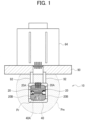
- FIG. 1 illustrates a diaphragm pressure gauge 10 according to a first embodiment of the invention.
- the diaphragm pressure gauge 10 includes two diaphragms 20, a detection element 30, and a structure 40.
- the structure 40 is disposed under pressure to be measured (Pm).
- the two diaphragms 20 are attached to the structure 40 so as to oppose each other.
- the detection element 30 is fixed to the two diaphragms 20.
- a flange 90 is a fixing member that disposes and fixes the structure 40 under the pressure to be measured (Pm).
- the flange 90 disposes the structure 40 under the pressure to be measured (Pm) by being attached to, for example, a vacuum chamber, and the like.
- the structure 40 can be attached to the flange 90 via a thermal insulator 92. Accordingly, even when the flange 90 is affected by environmental temperature, solid heat transfer of the environmental temperature can be blocked by the thermal insulator 92.
- a circuit block 94 including a drive circuit that drives the detection element 30, a signal output circuit, and the like is fixed to an atmosphere side of the flange 90.
- the detection element 30 that detects displacements of the two diaphragms 20 is, for example, a piezoelectric element such as an oscillator.
- each of the two diaphragms 20 one of two surfaces is designated an opposing surface 20A and the other surface is designated a non-opposing surface 20B.
- the structure 40 and the two diaphragms 20 set a space faced by one of the opposing surface 20A and the non-opposing surface 20B (the opposing surface 20A in FIG. 1 ) as an airtight space 40A to be kept in a reference vacuum (Pr).
- the other of the opposing surface 20A and the non-opposing surface 20B (the non-opposing surface 20B in FIG. 1 ) is subjected to the pressure to be measured (Pm).
- a known reference vacuum acts on the opposing surface 20A being one of the two surfaces while the pressure to be measured (Pm) acts on the non-opposing surface 20B being the other surface of the two surfaces, and the diaphragms 20 are displaced according to a differential pressure between the reference vacuum and the pressure to be measured. Since displacements of the two diaphragms 20 are equal in absolute values but opposite in directions, even if each displacement is small and ranges from, for example, 7 ⁇ m to 10 ⁇ m, sensitivity is doubled.
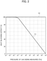
- FIG. 2 illustrates a correlation between the pressure to be measured (Pm) and a heat blocking effect.
- a vacuum region with lower pressure than atmospheric pressure (1.013 ⁇ 10 5 Pa) is classified into a low vacuum (10 5 to 10 2 Pa), a medium vacuum (10 2 to 10 -1 Pa), and a high vacuum (10 -1 to 10 -5 Pa). As illustrated in FIG.
- a measurement error accompanying a pressure fluctuation with respect to temperature is smaller when the pressure to be measured (Pm) ranges from atmospheric pressure to a medium vacuum (10 5 to 10 -1 Pa) than in a high vacuum (10 -1 to 10 -5 Pa). Therefore, when the pressure to be measured (Pm) ranges from atmospheric pressure to a medium vacuum (10 5 to 10 -1 Pa), even if the heat blocking effect of the pressure to be measured (Pm) is small, a measurement error accompanying a pressure fluctuation with respect to temperature can be ignored. Therefore, the pressure to be measured (Pm) between atmospheric pressure and a high vacuum can be accurately measured.
- the structure 40 can include an exhaust pipe 41 and a pump storage 42 that are communicated with the airtight space 40A.
- a deactivated getter pump 43 is stored in the pump storage 42.
- the two diaphragms 20 are attached to the structure 40 and, at the same time, both ends of the oscillator 30 are fixed to the two diaphragms 20. Subsequently, a lid is fixed to the one open face of the structure 40.
- a heater is wound around the pump storage 42 to activate the getter pump 43 at, for example, 500°C for, for example, 1 hour and, in doing so, gas is exhausted by a vacuum pump from a released end of the exhaust pipe 41. Subsequently, the pump storage 42 is cooled and the end of the exhaust pipe 41 is sealed.
- the airtight space 40A is set to the reference vacuum (Pr) of, for example, 10 -5 Pa.
- the structure 40 may include an exhaust pipe 44 that is communicated with the airtight space 40A.
- the exhaust pipe 44 can double as a storage for storing a getter pump 45.
- the structure 40 may include an inner structure 50 and an outer structure 52.
- the inner structure 50 supports the two diaphragms 20 that are disposed so as to oppose each other.
- the outer structure 52 can include an opening 52A inside which the inner structure 50 is supported and exposes the non-opposing surface 20B of the two diaphragms 20 in an atmosphere at the pressure to be measured (Pm). Accordingly, the airtight space 40A that is airtightly enclosed by the two diaphragms 20, the inner structure 50, and the outer structure 52 is set to the reference vacuum (Pr).
- the reference vacuum (Pr) acts on the opposing surface 20A and the pressure to be measured (Pm) acts on the non-opposing surface 20B.
- the inner structure 50 is disposed and fixed inside the outer structure 52. Accordingly, an assembly step is made to be easier than that of the structure 40 illustrated in FIG. 3A to FIG. 3C .
- the structure 40 may include an outer structure 60, the airtight space 40A provided inside of the outer structure 60 is set to the reference vacuum (Pr), and an inner structure 70 that is disposed inside the outer structure 60 and insulated by the reference vacuum (Pr).
- the inner structure 70 can include an introduction pipe 72 that has an inlet for a gas at pressure to be measured at a protruding end that protrudes outward from the outer structure 60 and an inner chamber 74 that is set to the pressure to be measured (Pm) via the introduction pipe 72.
- the two diaphragms 20 function as partitions of a part of the inner chamber 74, the pressure to be measured (Pm) acts on the opposing surface 20A, and the reference vacuum (Pr) acts on the non-opposing surface 20B.
- the inner chamber 74 can include a first chamber 80 set to the pressure to be measured (Pm) via the introduction pipe 72, a second chamber 82 that is communicated with the airtight space 40A inside the outer structure 60 and airtightly separated from the first chamber 80, and bellows 84 that partitions the first chamber 80 and the second chamber 82, that is coupled to the two diaphragms 20, and that is capable of deforming so as to allow displacements of the two diaphragms.
- the opposing surface 20A is disposed so as to face the inside of the first chamber 80 and the piezoelectric element 30 is disposed in the second chamber 82.
- the inner structure 70 can further include two rigid bodies 71 that couple the two diaphragms 20 and the bellows 84 to each other.
- each of the rigid bodies 71 can include an opening 71A that communicates the airtight space 40A set to the reference vacuum (Pr) and the second chamber 82 with each other.
- the inside of the bellows 84 is set to the reference vacuum (Pr) via a central hole formed in the two diaphragms 20 and the opening 71A.
- the piezoelectric element 30 is disposed under the reference vacuum (Pr) and the airtight space 40A surrounding the piezoelectric element 30 is also set to the reference vacuum (Pr).
- a heat blocking effect exhibits characteristics C2 illustrated in FIG. 2 and is not affected by temperature. For example, even when a heat source such as an evaporation source is present under the pressure to be measured, there is hardly any effect of temperature. In this manner, measurement accuracy of pressure can be further increased.
- a compound pressure gauge 200 according to a second embodiment of the invention includes the diaphragm pressure gauge 10 according to the first embodiment of the invention and an ionization vacuum gauge 100.
- the diaphragm pressure gauge 10 and the ionization vacuum gauge 100 are coupled by a coupling member 110 and are both disposed under the pressure to be measured (Pm).
- the coupling member 110 is fixed to a vacuum chamber.
- the ionization vacuum gauge 100 is configured as a hot cathode ionization gauge (a type that heats a filament and extracts thermions) or a cold cathode ionization gauge (a type that extracts electrons by field emission).
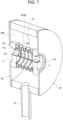
- a hot cathode ionization gauge as an example of the ionization vacuum gauge 100.
- the hot cathode ionization gauge 100 includes a filament 102, a grid 104, and a collector 106. When the filament 102 is energized, electrons are emitted from the filament 102.
- Electrons emitted from the filament 102 perform several reciprocating movements while heading towards the grid 104 and, during the movements, the electrons ionize a gas under the pressure to be measured (Pm).
- Pm pressure to be measured
- Pressure can be indirectly measured by measuring an ionic current created by ionized molecules and atoms flowing into the collector 106 having been negatively biased under a condition that a current (emission current) of thermions emitted from the filament 102 is constant.
- the filament 102 is more preferably disposed on an outer side of the spiral grid 104 in the hot cathode ionization gauge 100. Only one filament 102 may be disposed on the outer side. Accordingly, a decline in sensitivity can be suppressed even when the pressure to be measured (Pm) is relatively high. This is because molecules and atoms ionized by electrons emitted from the filament 102 are prevented from flowing into the collector 106 on an inner side of the spiral grid 104.
- Pm pressure to be measured
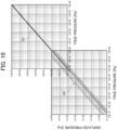
- FIG. 9 and FIG. 10 illustrate pressure characteristics of the compound pressure gauge 200.
- FIG. 10 is a characteristic diagram that serves as a basis of the characteristics illustrated in FIG. 9 indicating that a difference in sensitivity depending on gas species occurs in an ionic current of the ionization vacuum gauge 100 (characteristics C4') among the compound pressure gauge 200.
- characteristics C4' characteristics of the ionization vacuum gauge 100
- relative accuracy of pressure is as reliable as accuracy of reading.
- a level of a measured value of the diaphragm pressure gauge 10 (characteristics C3) is shifted on software to an upper-limit ionic current value of characteristics C4 of the ionization vacuum gauge 100 (a specific gas equivalent such as a nitrogen equivalent of an ionic current value with a proportional relationship between pressures regardless of gas species). Accordingly, with the compound pressure gauge 200 using the diaphragm pressure gauge 10 and the ionization vacuum gauge 100, true pressure is obtained as displayed pressure of the ionization vacuum gauge 100 regardless of a composition of a gas to be measured.
- the diaphragm pressure gauge 10 has a measurement range of, for example, atmospheric pressure (10 +5 Pa) to a medium vacuum (10 -2 Pa) and the ionization vacuum gauge 100 has a measurement range of, for example, a medium vacuum (1 Pa) to an ultrahigh vacuum (10 -7 Pa).
- the compound pressure gauge 200 can adopt a range of, for example, atmospheric pressure (10 +5 Pa) to an ultrahigh vacuum (10 -7 Pa) as a measurement range.
- the measurement region of the diaphragm pressure gauge 10 and the measurement region of the ionization vacuum gauge 100 overlap with each other by a range of 0.01 to 1.0 Pa in this example, the overlap region is not limited thereto.
- the overlap region may be 0.1 to 10.0 Pa, 0.1 to 1.0 Pa, or the like.
- a region from atmospheric pressure to an ultrahigh vacuum for example, 10 -7 Pa
- the compound pressure gauge 200 that is made up of the diaphragm pressure gauge 10 and the ionization vacuum gauge 100.
- the compound pressure gauge 200 is disposed under the pressure to be measured (Pm), a temperature of a measuring atmosphere is always the same as a temperature of an atmosphere under the pressure to be measured (Pm).
- the pressure to be measured (Pm) from atmospheric pressure to a low vacuum measurement error with respect to a temperature fluctuation in ambient air is small and the pressure to be measured (Pm) in this range can be measured by the diaphragm pressure gauge according to one of some aspects of the invention that does not include a heat source.
- the pressure to be measured (Pm) at a high vacuum or an ultrahigh vacuum is mainly measured by the hot cathode ionization gauge 100 that includes a heat source.
- the pressure to be measured (Pm) from atmospheric pressure to a high vacuum or an ultrahigh vacuum can be accurately measured.
- energization of the filament 102 may be turned on/off depending on a pressure value measured by the diaphragm pressure gauge 10. For example, energization of the filament 102 can be turned on when the pressure value measured by the diaphragm pressure gauge 10 is close to a measured upper limit or equal to or lower than the measured upper limit of the hot cathode ionization gauge 100 illustrated in FIG. 9 . In this manner, an adverse effect of the filament 102 being a heat source on the diaphragm pressure gauge 10 can be reduced.
- a zero point correction of the diaphragm pressure gauge 10 may be performed when the pressure to be measured (Pm) that is lower than a measured lower limit (10 -2 Pa in FIG. 9 ) of the diaphragm pressure gauge 10 is to be measured by the hot cathode ionization gauge 100. This is because, at the pressure to be measured (Pm) that is lower than the measured lower limit of the diaphragm pressure gauge 10, a measured value of the diaphragm pressure gauge 10 should be zero.
- a shield member 120 being a deposition preventive shield and/or a heat shield that surrounds the structure 40 may be further disposed. Since the shield member 120 is at least partially capable of allowing the gas to be measured to pass, the inside of the shield member 120 can be set to pressure of gas to be measured. In FIG. 8 , an entirety of the shield member 120 is formed of a porous sintered body such as ceramics. Accordingly, air permeability of the shield member 120 with respect to the gas to be measured is secured. In addition, even when, for example, a deposition source is disposed under the pressure to be measured (Pm) outside of the shield member 120, particles or heat from the deposition source can be blocked by the shield member 120.
- Pm pressure to be measured
- the shield member 120 has a function as a deposition preventive shield that blocks particles from a deposition source and prevents a film from forming on the diaphragm pressure gauge 10 and a function as a heat shield that prevents heat from the deposition source (heat source) from being transferred to the diaphragm pressure gauge 10.
- the shield member 120 may be an air-impermeable heat shield body that at least partially includes a filter or a baffle (baffle plate). In this case, air permeability and a function of a deposition preventive shield are secured by the filter or the baffle.
- a heat shield member 130 can be added to the coupling member 110.
- the heat shield member 130 can be made of a baffle (baffle plate). Accordingly, transfer of heat from the heat source (filament) of the hot cathode ionization gauge 100 to the diaphragm pressure gauge 10 can be prevented by the heat shield member 130.
- the shield member 120 illustrated in FIG. 8 that is a deposition preventive shield and/or a heat shield may be further disposed so as to surround the structure 40 illustrated in FIG. 1 .
Landscapes
- Physics & Mathematics (AREA)
- General Physics & Mathematics (AREA)
- Electromagnetism (AREA)
- Chemical & Material Sciences (AREA)
- Analytical Chemistry (AREA)
- Optics & Photonics (AREA)
- Measuring Fluid Pressure (AREA)
Applications Claiming Priority (1)
| Application Number | Priority Date | Filing Date | Title |
|---|---|---|---|
| JP2022045867A JP7096628B1 (ja) | 2022-03-22 | 2022-03-22 | 隔膜圧力計及び複合圧力計 |
Publications (2)
| Publication Number | Publication Date |
|---|---|
| EP4261514A2 true EP4261514A2 (de) | 2023-10-18 |
| EP4261514A3 EP4261514A3 (de) | 2023-11-15 |
Family
ID=82319550
Family Applications (1)
| Application Number | Title | Priority Date | Filing Date |
|---|---|---|---|
| EP22213007.2A Pending EP4261514A3 (de) | 2022-03-22 | 2022-12-13 | Membrandruckmesser und verbunddruckmesser |
Country Status (6)
| Country | Link |
|---|---|
| US (2) | US12442706B2 (de) |
| EP (1) | EP4261514A3 (de) |
| JP (1) | JP7096628B1 (de) |
| KR (1) | KR102781788B1 (de) |
| CN (1) | CN116793562A (de) |
| TW (1) | TWI823570B (de) |
Families Citing this family (1)
| Publication number | Priority date | Publication date | Assignee | Title |
|---|---|---|---|---|
| JP7375257B1 (ja) | 2023-08-30 | 2023-11-07 | Dmg森精機株式会社 | 工作機械、情報処理装置および制御プログラム |
Citations (3)
| Publication number | Priority date | Publication date | Assignee | Title |
|---|---|---|---|---|
| JPH0444636B2 (de) | 1985-02-08 | 1992-07-22 | Kuraray Co | |
| JP2007024849A (ja) | 2005-07-15 | 2007-02-01 | Toyo Denshi Kenkyusho:Kk | 多極型冷陰極電離真空計 |
| JP2010096763A (ja) | 2008-10-14 | 2010-04-30 | Itt Manufacturing Enterprises Inc | 電離真空計用分子シールド |
Family Cites Families (19)
| Publication number | Priority date | Publication date | Assignee | Title |
|---|---|---|---|---|
| US3965746A (en) * | 1974-11-04 | 1976-06-29 | Teledyne Industries, Inc. | Pressure transducer |
| JPH0719981A (ja) | 1993-06-01 | 1995-01-20 | Nippondenso Co Ltd | 高温用圧力センサ |
| JPH07294355A (ja) * | 1994-04-28 | 1995-11-10 | Nippondenso Co Ltd | 圧力センサ |
| JP2002005806A (ja) | 2000-06-16 | 2002-01-09 | Murata Mfg Co Ltd | 圧力測定方法および放出ガス量測定方法 |
| WO2007019714A1 (de) * | 2005-08-12 | 2007-02-22 | Inficon Gmbh | Optischer interferometrische drucksensor |
| JP2008008688A (ja) * | 2006-06-27 | 2008-01-17 | Yamatake Corp | 容量式圧力センサ |
| JP2009258085A (ja) * | 2008-03-25 | 2009-11-05 | Epson Toyocom Corp | 圧力センサおよびその製造方法 |
| JP2010019828A (ja) * | 2008-06-11 | 2010-01-28 | Epson Toyocom Corp | 圧力センサー用ダイアフラムおよび圧力センサー |
| JP2010025582A (ja) * | 2008-07-15 | 2010-02-04 | Epson Toyocom Corp | 圧力センサ |
| JP2010243276A (ja) * | 2009-04-03 | 2010-10-28 | Seiko Epson Corp | 相対圧力センサー、相対圧力測定装置及び相対圧力測定方法 |
| KR101114673B1 (ko) * | 2009-08-28 | 2012-03-13 | 세이코 엡슨 가부시키가이샤 | 압력 센서 |
| JP4926233B2 (ja) * | 2009-12-08 | 2012-05-09 | キヤノンアネルバ株式会社 | 複合型真空計 |
| JP5712666B2 (ja) * | 2011-02-18 | 2015-05-07 | セイコーエプソン株式会社 | 力検出器 |
| TWI739300B (zh) * | 2015-01-15 | 2021-09-11 | 美商Mks儀器公司 | 離子化計及其製造方法 |
| JP2017125850A (ja) | 2016-01-07 | 2017-07-20 | Q’z株式会社 | 真空計 |
| WO2020079773A1 (ja) * | 2018-10-17 | 2020-04-23 | Q’z株式会社 | 圧力計 |
| US11591929B2 (en) * | 2019-08-16 | 2023-02-28 | Rosemount Aerospace, Inc. | Sensor assemblies, gas turbines with sensor assemblies, and methods of cooling sensor assemblies |
| EP3998467B1 (de) * | 2019-09-13 | 2024-01-03 | Canon Anelva Corporation | Ionisationsvakuummeter und kartusche |
| KR102390110B1 (ko) * | 2019-09-13 | 2022-04-25 | 캐논 아네르바 가부시키가이샤 | 전리 진공계 및 카트리지 |
-
2022
- 2022-03-22 JP JP2022045867A patent/JP7096628B1/ja active Active
- 2022-09-16 TW TW111135124A patent/TWI823570B/zh active
- 2022-10-13 KR KR1020220131166A patent/KR102781788B1/ko active Active
- 2022-10-24 CN CN202211300136.5A patent/CN116793562A/zh active Pending
- 2022-12-13 EP EP22213007.2A patent/EP4261514A3/de active Pending
- 2022-12-15 US US18/066,358 patent/US12442706B2/en active Active
-
2025
- 2025-09-19 US US19/333,572 patent/US20260016357A1/en active Pending
Patent Citations (3)
| Publication number | Priority date | Publication date | Assignee | Title |
|---|---|---|---|---|
| JPH0444636B2 (de) | 1985-02-08 | 1992-07-22 | Kuraray Co | |
| JP2007024849A (ja) | 2005-07-15 | 2007-02-01 | Toyo Denshi Kenkyusho:Kk | 多極型冷陰極電離真空計 |
| JP2010096763A (ja) | 2008-10-14 | 2010-04-30 | Itt Manufacturing Enterprises Inc | 電離真空計用分子シールド |
Also Published As
| Publication number | Publication date |
|---|---|
| EP4261514A3 (de) | 2023-11-15 |
| US20230304883A1 (en) | 2023-09-28 |
| JP2023140031A (ja) | 2023-10-04 |
| KR102781788B1 (ko) | 2025-03-18 |
| TW202338311A (zh) | 2023-10-01 |
| TWI823570B (zh) | 2023-11-21 |
| JP7096628B1 (ja) | 2022-07-06 |
| KR20230137806A (ko) | 2023-10-05 |
| US20260016357A1 (en) | 2026-01-15 |
| US12442706B2 (en) | 2025-10-14 |
| CN116793562A (zh) | 2023-09-22 |
Similar Documents
| Publication | Publication Date | Title |
|---|---|---|
| US20260016357A1 (en) | Diaphragm pressure gauge and compound pressure gauge | |
| US5939639A (en) | Pressure transducer housing with barometric pressure isolation | |
| US6619131B2 (en) | Combination pressure sensor with capacitive and thermal elements | |
| US20120210799A1 (en) | Force detector | |
| CA2313313C (en) | Relative pressure sensor | |
| CA1090606A (en) | Vibrating diaphragm fluid pressure sensor device | |
| US4995263A (en) | Tuning fork quartz manometer | |
| JP2009162751A (ja) | 高温用静電容量式静圧/動圧センサ | |
| Wilfert et al. | Miniaturized vacuum gauges | |
| Tilford | Pressure and vacuum measurements | |
| CN100549648C (zh) | 皮拉尼真空计 | |
| JP4590100B2 (ja) | 圧力センサ、圧力測定装置およびチャンバで圧力をモニタするための方法 | |
| US20200103323A1 (en) | Sensor for comparative pressure measurement | |
| US10852207B2 (en) | Vacuum gauge | |
| Miiller | Measurement performance of high-accuracy low-pressure transducers | |
| Gascoigne | Precise pressure measurement in the range 0.1–500 torr | |
| ES2981337T3 (es) | Sistema y método para determinar la presión compensada por temperatura de un transductor de presión | |
| US20200191673A1 (en) | Capacitive Pressure Transducer | |
| US20200064213A1 (en) | Capacitance manometer for high temperature environments | |
| Jousten | Gauges for fine and high vacuum | |
| JP2012058063A (ja) | 圧力センサー | |
| Sellenger | A review of vacuum gauges and methods for high vacuum gauge calibration | |
| Steckelmacher | Review of vacuum gauges | |
| LIPTÁK et al. | 5.14 Vacuum Sensors | |
| Edelmann | Pressure measurement: total pressures |
Legal Events
| Date | Code | Title | Description |
|---|---|---|---|
| PUAI | Public reference made under article 153(3) epc to a published international application that has entered the european phase |
Free format text: ORIGINAL CODE: 0009012 |
|
| STAA | Information on the status of an ep patent application or granted ep patent |
Free format text: STATUS: REQUEST FOR EXAMINATION WAS MADE |
|
| PUAL | Search report despatched |
Free format text: ORIGINAL CODE: 0009013 |
|
| 17P | Request for examination filed |
Effective date: 20230106 |
|
| AK | Designated contracting states |
Kind code of ref document: A2 Designated state(s): AL AT BE BG CH CY CZ DE DK EE ES FI FR GB GR HR HU IE IS IT LI LT LU LV MC ME MK MT NL NO PL PT RO RS SE SI SK SM TR |
|
| AK | Designated contracting states |
Kind code of ref document: A3 Designated state(s): AL AT BE BG CH CY CZ DE DK EE ES FI FR GB GR HR HU IE IS IT LI LT LU LV MC ME MK MT NL NO PL PT RO RS SE SI SK SM TR |
|
| RIC1 | Information provided on ipc code assigned before grant |
Ipc: G01L 21/30 20060101ALI20231006BHEP Ipc: G01L 19/14 20060101ALI20231006BHEP Ipc: G01L 19/06 20060101ALI20231006BHEP Ipc: G01L 19/04 20060101ALI20231006BHEP Ipc: G01L 9/00 20060101AFI20231006BHEP |
|
| RBV | Designated contracting states (corrected) |
Designated state(s): AL AT BE BG CH CY CZ DE DK EE ES FI FR GB GR HR HU IE IS IT LI LT LU LV MC ME MK MT NL NO PL PT RO RS SE SI SK SM TR |
|
| RAP1 | Party data changed (applicant data changed or rights of an application transferred) |
Owner name: Q'Z CORPORATION |
|
| STAA | Information on the status of an ep patent application or granted ep patent |
Free format text: STATUS: EXAMINATION IS IN PROGRESS |
|
| 17Q | First examination report despatched |
Effective date: 20251020 |