EP4262006A1 - Phasenwechselmikrokapsel, separator, elektrodenplatte, batterie und elektrische vorrichtung - Google Patents
Phasenwechselmikrokapsel, separator, elektrodenplatte, batterie und elektrische vorrichtung Download PDFInfo
- Publication number
- EP4262006A1 EP4262006A1 EP22880029.8A EP22880029A EP4262006A1 EP 4262006 A1 EP4262006 A1 EP 4262006A1 EP 22880029 A EP22880029 A EP 22880029A EP 4262006 A1 EP4262006 A1 EP 4262006A1
- Authority
- EP
- European Patent Office
- Prior art keywords
- phase
- separator
- change
- tab
- coating layer
- Prior art date
- Legal status (The legal status is an assumption and is not a legal conclusion. Google has not performed a legal analysis and makes no representation as to the accuracy of the status listed.)
- Pending
Links
Images



Classifications
-
- C—CHEMISTRY; METALLURGY
- C09—DYES; PAINTS; POLISHES; NATURAL RESINS; ADHESIVES; COMPOSITIONS NOT OTHERWISE PROVIDED FOR; APPLICATIONS OF MATERIALS NOT OTHERWISE PROVIDED FOR
- C09K—MATERIALS FOR MISCELLANEOUS APPLICATIONS, NOT PROVIDED FOR ELSEWHERE
- C09K5/00—Heat-transfer, heat-exchange or heat-storage materials, e.g. refrigerants; Materials for the production of heat or cold by chemical reactions other than by combustion
- C09K5/02—Materials undergoing a change of physical state when used
- C09K5/06—Materials undergoing a change of physical state when used the change of state being from liquid to solid or vice versa
- C09K5/063—Materials absorbing or liberating heat during crystallisation; Heat storage materials
-
- H—ELECTRICITY
- H01—ELECTRIC ELEMENTS
- H01M—PROCESSES OR MEANS, e.g. BATTERIES, FOR THE DIRECT CONVERSION OF CHEMICAL ENERGY INTO ELECTRICAL ENERGY
- H01M10/00—Secondary cells; Manufacture thereof
- H01M10/60—Heating or cooling; Temperature control
- H01M10/65—Means for temperature control structurally associated with the cells
- H01M10/659—Means for temperature control structurally associated with the cells by heat storage or buffering, e.g. heat capacity or liquid-solid phase changes or transition
-
- H—ELECTRICITY
- H01—ELECTRIC ELEMENTS
- H01M—PROCESSES OR MEANS, e.g. BATTERIES, FOR THE DIRECT CONVERSION OF CHEMICAL ENERGY INTO ELECTRICAL ENERGY
- H01M10/00—Secondary cells; Manufacture thereof
- H01M10/60—Heating or cooling; Temperature control
- H01M10/65—Means for temperature control structurally associated with the cells
- H01M10/651—Means for temperature control structurally associated with the cells characterised by parameters specified by a numeric value or mathematical formula, e.g. ratios, sizes or concentrations
-
- H—ELECTRICITY
- H01—ELECTRIC ELEMENTS
- H01M—PROCESSES OR MEANS, e.g. BATTERIES, FOR THE DIRECT CONVERSION OF CHEMICAL ENERGY INTO ELECTRICAL ENERGY
- H01M10/00—Secondary cells; Manufacture thereof
- H01M10/60—Heating or cooling; Temperature control
- H01M10/65—Means for temperature control structurally associated with the cells
- H01M10/653—Means for temperature control structurally associated with the cells characterised by electrically insulating or thermally conductive materials
-
- H—ELECTRICITY
- H01—ELECTRIC ELEMENTS
- H01M—PROCESSES OR MEANS, e.g. BATTERIES, FOR THE DIRECT CONVERSION OF CHEMICAL ENERGY INTO ELECTRICAL ENERGY
- H01M10/00—Secondary cells; Manufacture thereof
- H01M10/60—Heating or cooling; Temperature control
- H01M10/65—Means for temperature control structurally associated with the cells
- H01M10/655—Solid structures for heat exchange or heat conduction
- H01M10/6553—Terminals or leads
-
- H—ELECTRICITY
- H01—ELECTRIC ELEMENTS
- H01M—PROCESSES OR MEANS, e.g. BATTERIES, FOR THE DIRECT CONVERSION OF CHEMICAL ENERGY INTO ELECTRICAL ENERGY
- H01M10/00—Secondary cells; Manufacture thereof
- H01M10/60—Heating or cooling; Temperature control
- H01M10/65—Means for temperature control structurally associated with the cells
- H01M10/655—Solid structures for heat exchange or heat conduction
- H01M10/6554—Rods or plates
- H01M10/6555—Rods or plates arranged between the cells
-
- H—ELECTRICITY
- H01—ELECTRIC ELEMENTS
- H01M—PROCESSES OR MEANS, e.g. BATTERIES, FOR THE DIRECT CONVERSION OF CHEMICAL ENERGY INTO ELECTRICAL ENERGY
- H01M10/00—Secondary cells; Manufacture thereof
- H01M10/60—Heating or cooling; Temperature control
- H01M10/65—Means for temperature control structurally associated with the cells
- H01M10/658—Means for temperature control structurally associated with the cells by thermal insulation or shielding
-
- H—ELECTRICITY
- H01—ELECTRIC ELEMENTS
- H01M—PROCESSES OR MEANS, e.g. BATTERIES, FOR THE DIRECT CONVERSION OF CHEMICAL ENERGY INTO ELECTRICAL ENERGY
- H01M50/00—Constructional details or processes of manufacture of the non-active parts of electrochemical cells other than fuel cells, e.g. hybrid cells
- H01M50/50—Current conducting connections for cells or batteries
- H01M50/531—Electrode connections inside a battery casing
- H01M50/534—Electrode connections inside a battery casing characterised by the material of the leads or tabs
-
- H—ELECTRICITY
- H01—ELECTRIC ELEMENTS
- H01M—PROCESSES OR MEANS, e.g. BATTERIES, FOR THE DIRECT CONVERSION OF CHEMICAL ENERGY INTO ELECTRICAL ENERGY
- H01M10/00—Secondary cells; Manufacture thereof
- H01M10/05—Accumulators with non-aqueous electrolyte
- H01M10/058—Construction or manufacture
- H01M10/0587—Construction or manufacture of accumulators having only wound construction elements, i.e. wound positive electrodes, wound negative electrodes and wound separators
-
- H—ELECTRICITY
- H01—ELECTRIC ELEMENTS
- H01M—PROCESSES OR MEANS, e.g. BATTERIES, FOR THE DIRECT CONVERSION OF CHEMICAL ENERGY INTO ELECTRICAL ENERGY
- H01M10/00—Secondary cells; Manufacture thereof
- H01M10/60—Heating or cooling; Temperature control
- H01M10/64—Heating or cooling; Temperature control characterised by the shape of the cells
- H01M10/643—Cylindrical cells
-
- H—ELECTRICITY
- H01—ELECTRIC ELEMENTS
- H01M—PROCESSES OR MEANS, e.g. BATTERIES, FOR THE DIRECT CONVERSION OF CHEMICAL ENERGY INTO ELECTRICAL ENERGY
- H01M4/00—Electrodes
- H01M4/02—Electrodes composed of, or comprising, active material
- H01M4/13—Electrodes for accumulators with non-aqueous electrolyte, e.g. for lithium-accumulators; Processes of manufacture thereof
-
- Y—GENERAL TAGGING OF NEW TECHNOLOGICAL DEVELOPMENTS; GENERAL TAGGING OF CROSS-SECTIONAL TECHNOLOGIES SPANNING OVER SEVERAL SECTIONS OF THE IPC; TECHNICAL SUBJECTS COVERED BY FORMER USPC CROSS-REFERENCE ART COLLECTIONS [XRACs] AND DIGESTS
- Y02—TECHNOLOGIES OR APPLICATIONS FOR MITIGATION OR ADAPTATION AGAINST CLIMATE CHANGE
- Y02E—REDUCTION OF GREENHOUSE GAS [GHG] EMISSIONS, RELATED TO ENERGY GENERATION, TRANSMISSION OR DISTRIBUTION
- Y02E60/00—Enabling technologies; Technologies with a potential or indirect contribution to GHG emissions mitigation
- Y02E60/10—Energy storage using batteries
Definitions
- This application relates to the field of batteries, and in particular, to a phase-change microcapsule, a separator, an electrode plate, a battery, and an electrical device.
- a current collection assembly is configured to electrically connect a tab of a battery cell and an electrode terminal, so that electrical energy is transferred from an electrode assembly to the electrode terminal and then transferred out of the battery cell through the electrode terminal.
- a plurality of battery cells are electrically connected to each other by a busbar component, so as to implement series, parallel, or series-and-parallel connection of the battery cells.
- This application provides a phase-change microcapsule, a separator, an electrode plate, a battery, and an electrical device, and can avoid the technical problem that a short circuit is prone to occur in the battery.
- this application exemplarily provides a phase-change microcapsule, including: a core and an insulative heat-conducting wall material wrapped around the core.
- the core includes a first phase-change component and a second phase-change component.
- the first phase-change component is paraffin with a melting point of 37 °C to 42 °C.
- the second phase-change component is paraffin with a melting point of 65 °C to 75 °C.
- a melting point of the insulative heat-conducting wall material is greater than 75 °C.
- a mass ratio between the first phase-change component and the second phase-change component is 35: (45 to 77).
- a phase-change microcapsule of a core-shell structure is provided, and is applied to a battery, such as a lithium battery, in the form of a coating layer.
- a negative tab of the lithium battery is connected to the separator by the coating layer in a close fitting manner.
- the first phase-change component and second phase-change component of a specified melting point are mixed at a specified ratio in the core, and coordinate with each other.
- the first phase-change component changes phase and quickly absorbs heat to cushion a heating rate of the separator and prevent an instantaneous temperature of the separator from exceeding a minimum scald-causing temperature before the second phase-change component changes the phase.
- the second phase-change component is caused to change the phase to continuously absorb a large amount of heat, and prevent a high temperature from scalding the separator at a later stage of laser welding.
- the melting point of the insulative heat-conducting wall material is greater than 75 °C, thereby letting the phase-changed core flow out of the insulative heat-conducting wall material without damaging the insulative heat-conducting wall material.
- the first phase-change component and the second phase-change component coordinate with each other to absorb the welding heat and melt in a stepped manner, thereby controlling the heating rate of the separator and the temperature of the separator, ensuring that a real-time temperature of the separator is always lower than the minimum scald-causing temperature during welding, and in turn, avoiding an internal short circuit of the battery caused by the scalded separator.
- a structural formula of the paraffin used as the first phase-change component is: C n H 2n+2 , where 18 ⁇ n ⁇ 21; and a structural formula of the paraffin used as the second phase-change component is: C n' H 2n'+2 , where 25 ⁇ n' ⁇ 28.
- the paraffin of the specified structural formula meets the melting point requirement satisfactorily, and possesses the advantage of abundant sources.
- the insulative heat-conducting wall material includes a substrate and ceramic particles dispersed in the substrate.
- the substrate is a polymer.
- the beneficial effects of the above technical solution include:
- the ceramic particles introduced in the wall material make the wall material more resistant to high temperatures, facilitate the core to absorb in time the heat generated during welding of the current collection assembly, and in addition, avoid excessive shrinkage of a contact part between the separator and the negative electrode plate during the welding.
- the polymer includes phenolic resin.
- a mass ratio between the wall material and the core is 1: (3 to 4).
- the beneficial effects of the above technical solution include: The mixing ratio between the wall material and the core is controlled to fall within a reasonable range; the thickness of the wall material can be controlled under the condition that the particle diameter of the phase-change microcapsule meets the use requirements, and the thickness of the wall material is ensured to be reasonable; and the phase-change microcapsule in use is ensured to be stable, and can serve a function of protecting the separator against an instantaneous high temperature during the welding.
- a mass ratio between the substrate and the ceramic particles is 3: (4 to 5), and a mass ratio between the substrate and the core is 1: (2 to 3).
- the beneficial effects of the above technical solution include: The content of the substrate, the ceramic particles, and the core is controlled to fall within the above range to ensure stability of the phase-change microcapsule, so that the phase-change microcapsule can serve a function of protecting the separator against an instantaneous high temperature during the welding.
- the ceramic particles include a silicon dioxide particle.
- the beneficial effects of the above technical solution include:
- the silicon dioxide particles are excellent in high-temperature resistance, insulation, and thermal conductivity, improve the performance of the wall material in high-temperature resistance, insulation, and thermal conductivity, improve the stability and heat absorption capacity of the phase-change microcapsule during welding of the current collection assembly, and possess advantages such as abundant sources and high availability.
- a particle diameter of the silicon dioxide particle is 60 to 90 nm.
- the beneficial effects of the above technical solution include:
- the above silicon dioxide particle of a specified particle diameter can be conveniently added as a dopant and uniformly dispersed in the substrate.
- a particle diameter of the phase-change microcapsule is 0.5 to 4 ⁇ m.
- the beneficial effects of the above technical solution include:
- the phase-change microcapsule with an appropriate particle diameter facilitates formation of a coating layer, and effectively avoids scalding the edge of the separator on the negative electrode side during welding of the current collection assembly.
- this application exemplarily provides a separator.
- An edge of the separator is coated with a coating layer.
- the coating layer contains the phase-change microcapsule according to the first aspect of this application.
- the coating layer on the edge of the separator corresponds to a tab with a heat transfer coefficient greater than or equal to 380 W/m ⁇ k.
- the coating layer absorbs the heat transferred by the tab during welding of the current collection assembly, ensures that a real-time temperature of the separator is always lower than the minimum scald-causing temperature during the welding, and in turn, avoids an internal short circuit of the battery caused by the scalded separator.
- the coating layer mainly located on the edge of the separator, basically does not affect the performance of the separator itself.
- a thickness of the coating layer is 10 to 35 ⁇ m, optionally 10 to 20 ⁇ m, and optionally 25 to 35 ⁇ m.
- the beneficial effects of the above technical solution include: The thickness of the coating layer is reasonable.
- the separator is applied to the battery, in a case that the tab is laser-welded to the current collection assembly, not only the separator is prevented from being scalded, but also the size of the edge of the separator is prevented from being much affected.
- this application exemplarily provides an electrode plate.
- the electrode plate includes a current collector and a tab connected to each other.
- a heat transfer coefficient of the tab is greater than or equal to 380 W/m ⁇ k.
- At least one side of the tab is coated with a coating layer.
- the coating layer contains the phase-change microcapsule according to the first aspect of this application.
- the beneficial effects of the above technical solution include:
- the heat transfer coefficient of the tab is greater than or equal to 380 W/m ⁇ k. Therefore, the tab is applied to a battery, and the coating layer containing the phase-change microcapsule is disposed between the tab and the separator to avoid direct contact between the separator and the tab.
- the coating layer can absorb the heat transferred by the tab, so that the real-time temperature of the separator is always lower than the minimum scald-causing temperature, thereby avoiding an internal short circuit caused by the scalded separator.
- a thickness of the coating layer is 10 to 35 ⁇ m, optionally 10 to 20 ⁇ m, and optionally 25 to 35 ⁇ m.
- the beneficial effects of the above technical solution include: The thickness of the coating layer is reasonable. During welding of the current collection assembly, not only the separator coordinating with the tab is prevented from being scalded, but also the size of the edge of the separator coordinating with the tab is prevented from being much affected.
- this application exemplarily provides a battery.
- the battery includes a separator and an electrode plate.
- the electrode plate includes a current collector and a tab connected to each other.
- a coating layer is applied between the tab and the separator, and the coating layer is formed on the tab and/or formed on the separator.
- the coating layer contains the phase-change microcapsule according to the first aspect of this application.
- the beneficial effects of the above technical solution include:
- the coating layer containing the phase-change microcapsule is applied between the tab and the separator, so that the coating layer absorbs the heat transferred by the tab during welding of the current collection assembly, ensures that a real-time temperature of the separator is always lower than the minimum scald-causing temperature during the welding, and in turn, avoids an internal short circuit of the battery caused by the scalded separator.
- a thickness of the coating layer between the separator and the tab is 20 to 35 ⁇ m.
- the beneficial effects of the above technical solution include: The thickness of the coating layer is reasonable. During welding of the current collection assembly, not only the edge of the separator coordinating with the tab is prevented from being scalded, but also the size of the edge of the separator is prevented from being much affected.
- this application provides an electrical device, equipped with the battery according to the fourth aspect of this application.
- first and second are merely intended to distinguish between different items but not intended to indicate or imply relative importance or implicitly specify the number of the indicated technical features, specific order, or order of precedence.
- the term "and/or” merely indicates a relationship between related items, and represents three possible relationships.
- “A and/or B” may represent the following three circumstances: A alone, both A and B, and B alone.
- the character “/” herein generally indicates an "or” relationship between the item preceding the character and the item following the character.
- a plurality of means two or more (inclusive of two).
- Power batteries are not only used in energy storage power systems such as hydro, thermal, wind, and solar power stations, but also widely used in electric means of transport such as electric bicycles, electric motorcycles, and electric vehicles, and used in many other fields such as military equipment and aerospace.
- the market demand for power batteries keeps soaring with the increase of the application fields of the power batteries.
- a short circuit is prone to occur inside a battery.
- a negative tab of the lithium-ion battery is generally a thin copper foil of relatively high thermal conductivity, but an instantaneous temperature of the laser welding of the current collection assembly is very high. Consequently, the edge of the separator at which the separator is in contact with the negative tab is scalded, for example, generates pores or shrinks excessively, resulting in an internal short circuit of the battery.
- the applicant tries applying a coating layer onto the edge at which the negative tab fits closely with the separator of the lithium battery, so as to isolate the negative tab from the separator and avoid direct contact in between.
- the applicant applies a phase-change material in the coating layer to absorb the heat transferred to the tab during laser welding, so as to reduce the temperature of the separator.
- the heat absorption performed by using the phase change of the phase-change material to reduce the temperature of the separator can solve the above technical problem.
- a phase-change response speed varies between different phase-change materials.
- a light emission time in the laser welding is generally 0.1 second, and an instantaneous temperature of the laser beam emitted is up to 1000 °C.
- the phase-change material is unable to respond quickly to the phase change during phase transition, and the instantaneous temperature of the separator is greater than the minimum scald-causing temperature.
- the separator is still prone to be scalded.
- the applicant provides a phase-change microcapsule, puts the phase-change microcapsule on the edge of the separator and/or at least one side of the tab, fits the parts together to form a battery cell, and applies the battery cell to a battery.
- the tab with a heat transfer coefficient greater than or equal to 380 W/m ⁇ k is connected to a current collection assembly by laser welding.
- a first phase-change component and a second phase-change component of different melting points are mixed at a specified ratio in the phase-change microcapsule, and coordinate with each other to implement stepped melting of the first phase-change component and the second phase-change component.
- a heating rate of the separator and a real-time temperature of the separator are controlled, thereby effectively avoiding the problem of an internal short circuit of the battery cell caused by the scald of the separator during the laser welding of the current collection assembly.
- the battery disclosed in some embodiments of this application is applicable to, but not limited to, electrical devices such as a vehicle, watercraft, or aircraft.
- a power supply system of the electrical device may be formed by using the battery disclosed in this application and the like, so as to avoid an internal short circuit of the battery and improve the performance stability and longevity of the battery.
- An embodiment of this application provides an electrical device powered by a battery.
- the electrical device may be, but without being limited to, a mobile phone, a tablet, a notebook computer, an electric toy, an electric tool, an electric power cart, an electric vehicle, a ship, a spacecraft, and the like.
- the electric toy may include stationary or mobile electric toys, such as a game console, an electric car toy, an electric ship toy, an electric airplane toy, and the like.
- the spacecraft may include an airplane, a rocket, a space shuttle, a spaceship, and the like.
- a vehicle 1000 is used as an example of the electrical device according to an embodiment of this application.
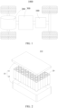
- FIG. 1 is a schematic structural diagram of a vehicle 1000 according to some embodiments of this application.
- the vehicle 1000 may be an oil-fueled vehicle, a natural gas vehicle, or a new energy vehicle.
- the new energy vehicle may be a battery electric vehicle, a hybrid electric vehicle, a range-extended electric vehicle, or the like.
- a battery 100 is disposed inside the vehicle 1000.
- the battery 100 may be disposed at the bottom, front, or rear of the vehicle 1000.
- the battery 100 may be configured to supply power to the vehicle 1000.
- the battery 100 may serve as an operating power supply of the vehicle 1000.
- the vehicle 1000 may further include a controller 200 and a motor 300.
- the controller 200 is configured to control the battery 100 to supply power to the motor 300, for example, to meet electrical energy requirements in starting, navigating, or running the vehicle 1000.
- the battery 100 serves not only as an operating power supply of the vehicle 1000, but may also serve as a drive power supply of the vehicle 1000 to provide driving power for the vehicle 1000 in place of or partly in place of oil or natural gas.
- FIG. 2 is an exploded view of a battery 100 according to some embodiments of this application.
- the battery 100 includes a box 10 and a battery cell 20.
- the battery cell 20 is accommodated in the box 10.
- the box 10 is configured to provide an accommodation space for the battery cell 20.
- the box 10 may be in various structures.
- the box 10 may include a first part 11 and a second part 12.
- the first part 11 and the second part 12 fit and cover each other.
- the first part 11 and the second part 12 together define an accommodation space configured to accommodate the battery cell 20.
- the second part 12 may be a hollow structure opened at one end.
- the first part 11 may be a plate-like structure.
- the first part 11 fits on an opening side of the second part 12 so that the first part 11 and the second part 12 together define the accommodation space.
- both the first part 11 and the second part 12 may be hollow structures opened at one side.
- the opening side of the first part 11 fits the opening side of the second part 12.
- the box 10 formed by the first part 11 and the second part 12 may be in various shapes, such as a cylinder or a cuboid.
- the battery 100 may contain a plurality of battery cells 20.
- the plurality of battery cells 20 may be connected in series, parallel, or series-and-parallel pattern.
- the series-and-parallel pattern means a combination of series connection and parallel connection of the plurality of battery cells 20.
- the plurality of battery cells 20 may be directly connected in series, parallel, or series-and-parallel pattern, and then the whole of the plurality of battery cells 20 may be accommodated in the box 10.
- the plurality of battery cells 20 may be connected in series, parallel, or series-and-parallel pattern to form a battery 100 in the form of battery modules first. A plurality of battery modules are then connected in series, parallel, or series-and-parallel pattern to form a whole for being accommodated in the box 10.
- the battery 100 may further include other structures.
- the battery 100 may further include a busbar component.
- the busbar component is configured to implement electrical connection between the plurality of battery cells 20.
- Each battery cell 20 may be, but without being limited to, a secondary battery or primary battery; or may be a lithium-sulfur battery, a sodium-ion battery, or a magnesium-ion battery.
- the battery cell 20 may be in the shape of a cylinder, flat body, cuboid, or the like.
- FIG. 3 is a schematic structural exploded view of a battery cell 20 according to some embodiments of this application.
- the battery cell 20 is a minimum unit for making up a battery.
- the battery cell 20 includes an end cap 21, an insulator 22, a current collection assembly 23, a housing 24, an electrode assembly 25, an electrolytic solution (not shown in the drawing), and other functional components.
- the end cap 21 is a component that fits and covers the opening of the housing 24 to isolate the internal environment of the battery cell 20 from the external environment.
- the shape of the end cap 21 may be adapted to the shape of the housing 24 to fit the housing 24.
- the end cap 21 may be made of a material of appropriate hardness and strength (such as aluminum alloy), so that the end cap 21 is not prone to deform when squeezed or impacted. In this way, the battery cell 20 achieves higher structural strength and higher safety performance.
- a pressure relief mechanism configured to release an internal pressure when the internal pressure or temperature of the battery cell 20 reaches a threshold may be further disposed on the end cap 21.
- the end cap 21 may also be made of a variety of materials such as copper, iron, aluminum, stainless steel, aluminum alloy, or plastic, without being particularly limited herein.
- Electrodes 21a are disposed on the end cap 21.
- the electrode terminals 21a may be configured to be electrically connected to the electrode assembly 25 to output or input electrical energy of the battery cell 20.
- a pressure relief mechanism configured to release an internal pressure when the internal pressure or temperature of the battery cell 20 reaches a threshold may be further disposed on the end cap 21.
- the end cap 21 may also be made of a variety of materials such as copper, iron, aluminum, stainless steel, aluminum alloy, or plastic, without being particularly limited herein.
- the insulator 22 is located on an inner side of the end cap 21.
- the insulator 22 may be configured to isolate an electrically connected component in the housing 24 from the end cap 21 to reduce short-circuit risks.
- the insulator 22 may be plastic, rubber, or the like.
- the current collection assembly 23 is located on a side of the insulator 22, the side being away from the end cap 21.
- the current collection assembly 23 is configured to electrically connect the electrode terminal 21a and the electrode assembly 25, so as to transmit electrical energy from the electrode assembly 25 to the electrode terminals 21a. Through the electrode terminals 21a, the electrical energy is transmitted out of the electrode assembly 25.
- the housing 24 is a component configured to fit the end cap 21 to form an internal environment of the battery cell 20.
- the formed internal environment may be used to accommodate the electrode assembly 25, an electrolytic solution, and other components.
- the housing 24 and the end cap 21 may be stand-alone components.
- An opening may be made on the housing 24.
- the end cap 21 fits with the opening to form the internal environment of the battery cell 20.
- the end cap 21 and the housing 24 may be integrated instead.
- the end cap 21 and the housing 24 may form a common connection interface before other components are put into the housing. Subsequently, when the interior of the housing 24 needs to be sealed, the end cap 21 is made to fit with the housing 24.
- the housing 24 may be in various shapes and sizes, such as a cuboid, cylinder, or hexagonal prism. Specifically, the shape of the housing 24 may be determined depending on the specific shape and size of the electrode assembly 25.
- the housing 24 may be made of a variety of materials such as copper, iron, aluminum, stainless steel, aluminum alloy, or plastic, without being particularly limited herein.
- the electrode assembly 25 is a component that reacts electrochemically in the battery cell 20.
- the housing 24 may contain one or more electrode assemblies 25.
- the electrode assembly 25 is typically formed of a positive electrode plate and a negative electrode plate that are wound or stacked together.
- a separator 256 is disposed between the positive electrode plate and the negative electrode plate.
- the positive electrode plate includes a positive current collector 251 coated with a positive active material on a surface.
- the negative electrode plate includes a negative current collector 253 coated with a negative active material on a surface.
- the positive current collector 251 coated with the positive active material and the negative current collector 253 coated with the negative active material jointly constitute a body portion of the electrode assembly 25.
- a positive tab 252 and a negative tab 255 are electrically connected to the corresponding positive current collector 251 and negative current collector 253 respectively, and are not coated with the active material on the surface.
- the positive tab 252 and the negative tab 255 may be located at one end of the body portion together or at two ends of the body portion respectively.
- the positive active material and the negative active material react with an electrolytic solution.
- the tabs 23a are connected to electrode terminals 21a to form a current circuit.
- the heat transfer coefficient of the negative tab 255 is greater than or equal to 380 W/m ⁇ k.
- FIG. 4 is obtained by unwinding the electrode assembly 25.
- FIG. 4 is a schematic structural view of the unwound electrode assembly 25.
- the separator 256 includes an edge region 257.
- the edge of the separator 256 is a long-side edge of the separator 256, the long-side edge being close to the negative tab 255 with a heat transfer coefficient greater than or equal to 380 W/m ⁇ k.
- the edge is an edge of the separator 256 that is close to the negative tab 255 with a heat transfer coefficient greater than or equal to 380 W/m ⁇ k.
- the negative electrode plate includes a tab region 258.
- an edge of the separator 256 which is oriented toward and protrudes beyond the negative current collector 253 and is used to fit closely with the negative tab 255, serves as the edge region 257 of the separator.
- the edge region 257 of the separator is coated with a coating layer 259 that contains a phase-change microcapsule.
- the separator 256 protrudes beyond the tab by a length not greater than 4 mm. Therefore, the width of the edge region 257 of the separator is greater than or equal to 4 mm, and is less than or equal to 8 mm.
- An end of the separator 256, which protrudes beyond the negative tab 255, is a first end; and the other end opposite to the first end serves as a second end.
- the width of the edge region is obtained by extending the separator 256 from the first end to the second end.
- the width here means a distance by which the separator 256 extends from the first end in the extension direction.
- the schematic structural diagram of a flattened negative electrode region shown in FIG. 5 is obtained by bending the edge region 257 of the separator and the negative tab 255 concurrently.
- the tab region 258 includes the edge region 257 of the separator, the coating layer 259, and the negative tab 255.
- the coating layer 259 of the tab region 258 is located directly under the negative tab 255, and the negative tab 255 fits closely with the edge region 257 of the separator through the coating layer 259.
- the thickness of the coating layer 259 may be 25 to 35 ⁇ m, and specifically, may be 30 ⁇ m, for example.
- the negative tab 255 of the flattened negative electrode region is laser-welded to the current collection assembly 23.
- a laser beam is cast downward from the top of the current collection assembly 23 to weld the current collection assembly 23 and the negative tab 255 together.
- the heat is transferred from the current collection assembly 23 to the negative tab 255, and then the heat is transferred by the negative tab 255 to the coating layer 259 and absorbed by the coating layer 259, thereby protecting the edge region 257 of the separator located in the tab region 258.
- this application provides a phase-change microcapsule, including: a core and an insulative heat-conducting wall material wrapped around the core.
- the core includes a first phase-change component and a second phase-change component.
- the first phase-change component is paraffin with a melting point of 37 °C to 42 °C.
- the second phase-change component is paraffin with a melting point of 65 °C to 75 °C.
- a melting point of the insulative heat-conducting wall material is greater than 75 °C.
- a mass ratio between the first phase-change component and the second phase-change component is 35: (45 to 77).
- the core means a material enclosed as a content in the insulative heat-conducting wall material.
- the phase-change microcapsule according to this application is of a core-shell structure.
- the wall material is insulative under the working conditions of the battery, that is, possesses a good resistivity, for example, a resistivity of 1013 ⁇ cm to 1014 ⁇ cm, so that the phase-change microcapsule coating layer is highly insulative as a whole.
- the wall material possesses a good heat transfer coefficient, for example, a heat transfer coefficient of 0.22 W/m K or higher than 0.22 W/m K, or the like, so that the phase-change microcapsule is highly effective in absorbing heat and can absorb in time the heat generated during the welding of the current collection assembly, thereby achieving the purpose of preventing the separator from being scalded.
- the wall material is inert under the working state of the battery, and does not react with the electrolytic solution.
- the melting point of the wall material is greater than 75 °C.
- the heat transfer coefficient of the tab being greater than or equal to 380 W/m ⁇ k, in a process of connecting the tab to the current collection assembly by laser welding, the phase-changed molten core flows out of the insulative heat-conducting wall material without damaging the insulative heat-conducting wall material.
- the core includes a first phase-change component and a second phase-change component. Both the first phase-change component and the second phase-change component are paraffin, and therefore, can be well mixed conveniently.
- the first phase-change component is paraffin with a melting point of 37 °C to 42 °C.
- the second phase-change component is paraffin with a melting point of 65 °C to 75 °C.
- the first phase-change component and the second phase-change component not only achieve good thermal phase transition performance, but also achieve a relatively high endothermic value during the phase transition.
- the highest melting point of the first phase-change component is significantly lower than the lowest melting point of the second phase-change component.
- the first phase-change component at a relatively low temperature responds to the phase change quickly first, and absorbs enough heat to change the phase into a liquid state, so as to cushion the heating rate of the separator and control the real-time temperature of the separator.
- the second phase-change component absorbs a large amount of heat to change the phase into a liquid state, so as to further reduce the heating rate of the separator and control the real-time temperature of the separator.
- the first phase-change component and the second phase-change component transform from a solid state to a liquid state.
- the first phase-change component and the second phase-change component are distributed uniformly, and therefore, can be melted in a stepped manner when the temperatures of the two components increase as a whole. In this way, the real-time temperature of the separator is controlled to be always lower than the minimum scald-causing temperature of the separator. Meanwhile, the core as a whole is sealed in the chemically inert wall material.
- the mass ratio between the first phase-change component and the second phase-change component affects the heating rate and temperature of the separator during welding of the current collection assembly.
- An appropriate mass ratio between the first phase-change component and the second phase-change component ensures a high overall capacity of heat absorption of the core while avoiding an excessive heating rate of the separator, thereby effectively reducing the temperature of the separator. If the mass percent of the first paraffin component is excessive, the overall capacity of heat absorption of the core will be insufficient, and in turn, the real-time temperature of the separator is higher than the minimum scald-causing temperature of the separator. If the mass percent of the first paraffin component is insufficient, the phase-change response time left for the second phase-change component is short.
- the separator is heated up rapidly, and the real-time temperature of the separator is higher than the minimum scald-causing temperature under the impact of the rapid temperature rise, making the separator prone to be scalded.
- the mass ratio between the first phase-change component and the second phase-change component is 35: 45, 35: 47, 35: 50, 35: 55, 35: 60, 35: 65, 35: 70, 35: 75, 35: 77, or a ratio value falling within a range formed by any two thereof.
- the first phase-change component may be one type of paraffin with a melting point of 37 °C to 42 °C, or may be a mixture of at least two types of paraffin with a melting point of 37 °C to 42 °C mixed at any ratio.
- the composition of the second phase-change component is obtained, without being limited herein.
- a structural formula of the paraffin used as the first phase-change component is: C n H 2n+2 , where 18 ⁇ n ⁇ 21; and a structural formula of the paraffin used as the second phase-change component is: C n' H 2n'+2 , where 25 ⁇ n' ⁇ 28.
- a mass ratio between the wall material and the core is 1: (3 to 4).
- the mass ratio between the wall material and the core is 1: 3, 1: 3.3, 1: 3.5, 1: 3.7, 1: 3.9, 1:4, or a ratio value falling within a range formed by any two thereof.
- the mass ratio falling within the above range can limit the thickness of the wall material and improve the stability of the phase-change microcapsule.
- the insulative heat-conducting wall material includes a substrate and ceramic particles dispersed in the substrate.
- the substrate is a polymer.
- the ceramic particles are particles made of ceramic materials that is resistant to high temperatures and thermally conductive.
- the material of the ceramic particles includes but not limited to at least one of boron nitride, silicon nitride, silicon carbide, silicon dioxide, or the like.
- the polymer is well compatible with paraffin and is insulative.
- the polymer includes phenolic resin. That is, the polymer includes but is not limited to phenolic resin, and instead, may be any one of polyacrylonitrile resin, melamine formaldehyde resin, or a phenolic resin polymer.
- the wall material is highly insulative, and the ceramic particles introduced in the wall material make the wall material more resistant to high temperatures, facilitate the core to absorb in time the heat generated during welding of the current collection assembly, and in addition, avoid excessive shrinkage of a contact part between the separator and the negative electrode plate during the welding.
- the polymer as a substrate, it is ensured that the wall material is well compatible with the paraffin, and can form a stable interface between the wall material and the paraffin, thereby improving the thermal stability of the phase-change microcapsule.
- the polymer is phenolic resin.
- the substrate made of the above material is more compatible with the paraffin, facilitates uniform dispersion of the ceramic particles, and ensures stability of the phase-change microcapsule.
- a mass ratio between the substrate and the ceramic particles is 3: (4 to 5), and a mass ratio between the substrate and the core is 1: (2 to 3).
- the mass ratio between the substrate and the ceramic particles is any one of 3: 4, 3: 4.3, 3: 4.5, 3: 4.6, 3: 4.9, 3:5, or a ratio value falling within a range formed by any two thereof.
- the mass ratio between the substrate and the core is 1: 2, 1: 2.3, 1: 2.5, 1: 2.7, 1: 2.9, 1:3, or a ratio value falling within a range formed by any two thereof.
- the content of the substrate, the ceramic particles, and the core is controlled to fall within the above range to ensure stability of the phase-change microcapsule, so that the phase-change microcapsule can serve a function of protecting the separator against an instantaneous high temperature during the welding.
- the ceramic particles are silicon dioxide particles. Being excellent in high-temperature resistance, insulation, and thermal conductivity, the silicon dioxide particles improve the performance of the wall material in high-temperature resistance, insulation, and thermal conductivity, improve the stability and heat absorption capacity of the phase-change microcapsule during welding of the current collection assembly, and possess advantages such as abundant sources and high availability.
- a particle diameter of the silicon dioxide particle is 60 to 90 nm.
- the particle diameter mentioned here means an average particle diameter of the silicon dioxide particles.
- the particle diameter of the silicon dioxide particles is any one of 60 nm, 65 nm, 70 nm, 75 nm, 80 nm, 83 nm, 85 nm, or 90 nm, or a value falling within a range formed by any two thereof.
- the above silicon dioxide particle of a specified particle diameter can be conveniently added as a dopant and uniformly dispersed in the substrate.
- the particle diameter of the phase-change microcapsule is 0.5 to 4 ⁇ m.
- the particle diameter mentioned here means an average particle diameter of the phase-change microcapsules.
- the phase-change microcapsule of this size facilitates formation of a coating layer between the tab and the edge of the separator, and, when the tab is laser-welded to the current collection assembly, effectively avoids scalding the edge of the separator that coordinates with the tab.
- the phase-change microcapsule may be obtained by wrapping the wall material around the core by in-situ polymerization.
- the in-situ polymerization process is: Dispersing a mixture of one or more phase-change materials in water under the action of an emulsifier to form an oil-in-water emulsion, adding dropwise one or more water-soluble monomers or a low-molecular-weight prepolymer water solution of resin into the emulsion at a time or stepwise, and adjusting the stirring speed, reaction temperature, pH, and the like of the system to actuate a polycondensation reaction so that micromolecules (such as water molecules) are further removed between the prepolymer molecules to generate a non-water-soluble polycondensate at an interface of the emulsion, where the polycondensate is of a cross-linked three-dimensional mesh structure, thereby forming a phase-change microcapsule in which a phase-change material is encapsulated.
- a method for preparing a phase-change microcapsule includes:
- a method for preparing a phase-change microcapsule includes:
- phase-change microcapsule can be mass-produced by a controllable method.
- Steps of putting the powder into use include: mixing the powder with a binder to form a slurry at a practically required mixing ratio.
- Steps of putting the phase-change microcapsules into use include: adding a binder directly into the polymerized phase-change microcapsule emulsion without a drying process after the polymer is formed on the surface of the core by in-situ polymerization, and stirring the mixture to form a slurry ready for use.
- the binder is configured to fix the phase-change microcapsule onto the separator or tab.
- the binder includes, but is not limited to, aqueous styrene-butadiene rubber (SBR) binder, and sodium carboxymethyl cellulose (CMC).
- SBR aqueous styrene-butadiene rubber
- CMC sodium carboxymethyl cellulose
- the binder is a discrete SBR binder or a mixture of CMC and SBR mixed at a mass ratio of 3: (6 to 8).
- this application provides a separator.
- An edge of the separator is coated with a coating layer.
- the coating layer contains a phase-change microcapsule.
- the edge of the separator is a long-side edge of the separator, the long-side edge being close to the tab with a heat transfer coefficient greater than or equal to 380 W/m ⁇ k.
- the edge is an edge of the separator that is close to the tab with a heat transfer coefficient greater than or equal to 380 W/m ⁇ k.
- the coating layer includes a substrate and phase-change microcapsules dispersed in the substrate.
- the substrate means a material which, attached to the surface of the separator, the phase-change microcapsules can be dispersed in and a film can be formed on.
- the substrate is a binder.
- the binder may be, for example, an SBR binder and/or CMC.
- the SBR binder is of high thermal stability. Both the SBR binder and the CMC are highly compatible with the phase-change capsule.
- the separator is made of a material including but not limited to polypropylene (polypropylene, PP), polyethylene (polyethylene, PE), or the like. The specific material may be selected according to actual needs, and is not limited herein.
- the coating layer completely covers the edge of the separator, where the term "all-tab” means a tab being the edge of the current collector.
- the coating layer may completely cover the edge of the separator. In this way, after the tab is bent, the separator is completely isolated from the tab by using the coating layer, or the coating layer is disposed on a part corresponding to the tab on the edge, and the separator can also be completely isolated from the tab by using the coating layer.
- single-tab means that only one tab protrudes from each electrode plate to conduct a current.
- multi-tab means that at least two tabs protrude out of each electrode plate to conduct a current.
- a thickness of the coating layer is 10 to 35 ⁇ m, optionally 10 to 20 ⁇ m, and optionally 25 to 35 ⁇ m.
- the thickness of the coating layer formed on the separator is 10 to 20 ⁇ m; when only the separator is coated but the tab is not coated, the thickness of the coating layer formed on the separator is 25 to 35 ⁇ m, for example, is any one of 25 ⁇ m, 27 ⁇ m, 28 ⁇ m, 30 ⁇ m, or 35 ⁇ m, or a value falling within a range formed by any two thereof.
- the thickness of the coating layer falling within a reasonable range ensures that the temperature and the heating rate of the separator can be effectively adjusted, without much affecting the size of the edge of the separator.
- the coating layer may be prepared in the following manner: Mixing the phase-change microcapsules provided in the first aspect and a binder at a mass ratio such as 1: (7 to 9) to form a coating slurry, applying the slurry onto the edge of the separator, and drying the slurry to form the coating layer; or, adding a binder directly into the polymerized phase-change microcapsule emulsion, for example, adding CMC dry powder first, and then adding an SBR emulsion after the CMC is thoroughly dissolved, where the mass ratio between the CMC and the SBR is 3: 7, so as to form a coating slurry, and then applying the slurry onto the edge of the separator, and drying the slurry at 70 °C to 80 °C to form the coating layer.
- a binder directly into the polymerized phase-change microcapsule emulsion for example, adding CMC dry powder first, and then adding an SBR emulsion after the CMC is thoroughly dissolved, where the mass ratio between the CMC
- this application provides an electrode plate.
- the electrode plate includes a current collector and a tab connected to each other.
- a heat transfer coefficient of the tab is greater than or equal to 380 W/m ⁇ k.
- At least one side of the tab is coated with a coating layer.
- the coating layer contains the phase-change microcapsule according to the first aspect of this application.
- the coating layer includes a substrate and phase-change microcapsules dispersed in the substrate.
- the substrate means a material which, attached to the surface of the separator, the phase-change microcapsules can be dispersed in and a film can be formed on.
- the substrate is a binder.
- the binder may be an SBR binder.
- the binder is of high thermal stability, and is highly compatible with the phase-change capsule.
- the coating layer may extend from the tab to the current collector.
- the separator protrudes beyond the tab by a length that is generally not more than 4 mm. Therefore, optionally, the width of the coating layer on the tab is greater than or equal to 1 mm and less than or equal to 4 mm, and the width of the coating layer on the current collector is greater than or equal to 0 and less than or equal to 4 mm. That is, the total width of the coating layer is greater than or equal to 4 mm and less than or equal to 8 mm.
- the width of the coating layer here is a distance from an end of the coating layer close to the current collector to an end away from the current collector.
- the heat transfer coefficient of the tab is greater than or equal to 380 W/m ⁇ k. That is, the tab is a metal of high thermal conductivity.
- the tab is made of a material such as copper, silver, or silver-plated copper.
- the tab is made of copper.
- the tab and the current collector may be welded together or formed in one piece.
- the electrode plate may be a single-tab electrode plate, a multi-tab electrode plate, or an all-tab electrode plate, without being limited herein.
- a thickness of the coating layer is 10 to 35 ⁇ m, optionally 10 to 20 ⁇ m, and optionally 25 to 35 ⁇ m.
- the thickness of the coating layer formed on the tab is 10 to 20 ⁇ m; when only the tab is coated but the separator is not coated, the thickness of the coating layer formed on the tab is 25 to 35 ⁇ m, for example, is any one of 25 ⁇ m, 27 ⁇ m, 28 ⁇ m, 30 ⁇ m, or 35 ⁇ m, or a value falling within a range formed by any two thereof.
- the thickness of the coating layer falling within a reasonable range ensures that the temperature and the heating rate of the separator can be effectively adjusted, without much affecting the size of the edge of the separator that coordinates with the tab.
- the coating layer may be prepared in the following manner: Mixing the phase-change microcapsules provided in the first aspect and a binder at a mass ratio such as 1: (7 to 9) to form a coating slurry, applying the slurry onto the tab, and drying the slurry to form the coating layer; or, adding a binder directly into the polymerized phase-change microcapsule emulsion, for example, adding CMC dry powder first, and then adding an SBR emulsion after the CMC is thoroughly dissolved, where the mass ratio between the CMC and the SBR is 3: 7, so as to form a coating slurry, and then applying the slurry onto the tab, and drying the slurry at 70 °C to 80 °C to form the coating layer.
- a binder directly into the polymerized phase-change microcapsule emulsion for example, adding CMC dry powder first, and then adding an SBR emulsion after the CMC is thoroughly dissolved, where the mass ratio between the CMC and the SBR is 3: 7,
- this application provides a battery.
- the battery includes a separator and an electrode plate.
- the electrode plate includes a current collector and a tab connected to each other.
- a heat transfer coefficient of the tab is greater than or equal to 380 W/m k.
- a coating layer is applied between the tab and the separator.
- the coating layer is formed on the tab and/or formed on the separator.
- the coating layer contains the phase-change microcapsule according to the first aspect of this application.
- the edge of the separator is isolated from the tab by use of the coating layer to avoid direct contact between the separator and the tab. Therefore, during welding of the current collection assembly, the coating layer absorbs the heat transferred by the tab, reduces the heat transferred to the separator, and controls the heating rate of the separator, thereby ensuring that the real-time temperature of the separator is always lower than the minimum scald-causing temperature during the welding, and in turn, avoiding an internal short circuit caused by the scalded separator.
- the thickness of the coating layer between the separator and the electrode plate is 20 to 35 ⁇ m.
- the thickness of the coating layer is any one of 20 ⁇ m, 25 ⁇ m, 28 ⁇ m, 30 ⁇ m, 32 ⁇ m, or 35 ⁇ m, or a value falling within a range formed by any two thereof. The thickness of the coating layer falling within a reasonable range ensures that the temperature and the heating rate of the separator can be effectively adjusted, without much affecting the size of the edge of the separator.
- the coating layer is formed on just a single side of the tab and located between the tab and the separator. In this case, the thickness of the coating layer is 20 to 35 ⁇ m.
- the coating layer is formed on just the edge of the separator and located between the tab and the separator. In this case, the thickness of the coating layer is 20 to 35 ⁇ m.
- a first coating layer is formed on the tab, a second coating layer is formed on the edge of the separator, and the first coating layer fits closely with the second coating layer.
- the thickness of the first coating layer is 10 to 20 ⁇ m
- the thickness of the second coating layer is 10 to 20 ⁇ m
- a total thickness of the first coating layer and the second coating layer is 20 to 35 ⁇ m.
- this application exemplarily provides an electrical device, equipped with the battery disclosed in any one of the foregoing technical solutions.
- the electrical device may be any device or system powered by the battery.
- phase-change microcapsule the separator, the electrode plate, the battery, and the electrical device according to this application with reference to some embodiments.
- a phase-change microcapsule is provided, and is made by a method including:
- the first phase-change material when the melting point of the first phase-change material is 37 °C/39 °C, the first phase-change material is obtained by mixing the paraffin of a melting point 37 °C and the paraffin of a melting point 39 °C at a mass ratio of 1: 1; when the melting point of the first phase-change material is 65 °C/70 °C, the first phase-change material is obtained by mixing the paraffin of a melting point 65 °C and the paraffin of a melting point 70 °C at a mass ratio of 1: 1.
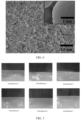
- FIG. 6 is a scanning electron microscope image of a phase-change microcapsule according to Embodiment 1. As can be seen from FIG. 6 , the particle diameter of the phase-change microcapsule is 0.5 to 4 ⁇ m.
- the CMC dry powder shown in Table 2 is added into the phase-change microcapsule emulsions prepared in Embodiments 1 to 7 and Comparative Embodiments 1 to 5. Subsequently, the CMC dry powder dissolves, the SBR emulsion shown in Table 2 is added to form a slurry. The slurry is applied onto the edges of the separators of the same dimensions (the separator are 9310 mm in length, 128.5 mm in width, and made of a PP material, and the edge of the separator is 8 mm in width).
- the slurry is dried so that a 20 ⁇ m-thick coating layer containing the phase-change microcapsule exists between the edge of the separator and the copper foil (serving as a tab, the heat transfer coefficient of copper foil being 400 W/ (m-K)).
- the tab is flattened, and then a side of the copper foil away from the separator is fastened to the current collection plate.
- the laser beams of the same parameters are cast downward from the top of current collection plates of the same specifications and materials.
- the current collection plate is welded to the copper foil by laser welding (the light emission time is 0.1 s, and the instantaneous temperature of the laser beam is 1000 °C). After completion of the welding, the separator is unwound, and the change of a side of the separator is observed, the side being away from the coating layer.
- the test results are shown in FIG. 7 and FIG. 8 .
- the tab needs to be flattened and then unwound during the test. Therefore, creases inevitably occur on the surface of the separator.
- the edge of the separator in Embodiments 1 to 7 is flat and neat without scalds.
- the boxed part in FIG. 8 is a scalded part on the edge of the separator.
- the edge region of the separator in Comparative Embodiments 1 to 5 exhibits scald-induced shrinkage and notches and other defects to varying degrees in contrast to Embodiment 1.
- phase-change microcapsule according to this application is applicable to the battery in the form of a coating layer, so that a bent tab is connected to the separator by the coating layer in a close fitting manner.
- the specified first phase-change component and second phase-change component of a specified melting point are mixed at a specified ratio in the core, and coordinate with each other to avoid scalding the separator and avoid an internal short circuit of the battery when a tab is laser-welded to a current collection assembly.
Landscapes
- Chemical & Material Sciences (AREA)
- Engineering & Computer Science (AREA)
- Chemical Kinetics & Catalysis (AREA)
- Electrochemistry (AREA)
- General Chemical & Material Sciences (AREA)
- Manufacturing & Machinery (AREA)
- Physics & Mathematics (AREA)
- General Physics & Mathematics (AREA)
- Algebra (AREA)
- Mathematical Analysis (AREA)
- Mathematical Optimization (AREA)
- Pure & Applied Mathematics (AREA)
- Combustion & Propulsion (AREA)
- Thermal Sciences (AREA)
- Materials Engineering (AREA)
- Organic Chemistry (AREA)
- Secondary Cells (AREA)
- Connection Of Batteries Or Terminals (AREA)
Applications Claiming Priority (2)
| Application Number | Priority Date | Filing Date | Title |
|---|---|---|---|
| CN202111189223.3A CN115966839B (zh) | 2021-10-12 | 2021-10-12 | 相变微胶囊、隔膜、极片、电池和用电装置 |
| PCT/CN2022/116271 WO2023061083A1 (zh) | 2021-10-12 | 2022-08-31 | 相变微胶囊、隔膜、极片、电池和用电装置 |
Publications (2)
| Publication Number | Publication Date |
|---|---|
| EP4262006A1 true EP4262006A1 (de) | 2023-10-18 |
| EP4262006A4 EP4262006A4 (de) | 2024-07-17 |
Family
ID=85894889
Family Applications (1)
| Application Number | Title | Priority Date | Filing Date |
|---|---|---|---|
| EP22880029.8A Pending EP4262006A4 (de) | 2021-10-12 | 2022-08-31 | Phasenwechselmikrokapsel, separator, elektrodenplatte, batterie und elektrische vorrichtung |
Country Status (4)
| Country | Link |
|---|---|
| US (1) | US20230395903A1 (de) |
| EP (1) | EP4262006A4 (de) |
| CN (1) | CN115966839B (de) |
| WO (1) | WO2023061083A1 (de) |
Families Citing this family (6)
| Publication number | Priority date | Publication date | Assignee | Title |
|---|---|---|---|---|
| CN116693267B (zh) * | 2023-06-07 | 2024-01-16 | 珠海横琴超元科技有限公司 | 基于绿色建筑用储能天花墙体复合材料及其制造方法 |
| CN117013080B (zh) * | 2023-09-06 | 2025-09-02 | 四川鸿鹏新材料有限公司 | 一种阻燃微胶囊及其制备方法、阻燃电解液 |
| CN118978357B (zh) * | 2024-10-21 | 2025-02-11 | 湖南工程学院 | 一种相变材料及其制备方法和应用 |
| CN122291788A (zh) * | 2024-12-24 | 2026-06-26 | 宁德时代新能源科技股份有限公司 | 电池单体、电池装置及用电设备 |
| CN120914452A (zh) * | 2025-08-25 | 2025-11-07 | 惠州锂威新能源科技有限公司 | 一种隔膜、二次电池和用电装置 |
| CN121440031A (zh) * | 2025-12-11 | 2026-01-30 | 惠州锂威新能源科技有限公司 | 隔膜和电化学装置 |
Family Cites Families (16)
| Publication number | Priority date | Publication date | Assignee | Title |
|---|---|---|---|---|
| JP3723554B2 (ja) * | 2003-03-19 | 2005-12-07 | 正隆股▲ふん▼有限公司 | 保温機能を具えた防水透湿薄膜及びその製造方法 |
| US8758925B2 (en) * | 2004-08-06 | 2014-06-24 | Lg Chem, Ltd. | Battery system containing phase change material-containing capsules in interior configuration thereof |
| US10164301B2 (en) * | 2011-06-07 | 2018-12-25 | All Cell Technologies, Llc | Energy storage thermal management system using multi-temperature phase change materials |
| CN104124491A (zh) * | 2013-04-26 | 2014-10-29 | 上海卡耐新能源有限公司 | 一种可自行调控工作温度的电池及其制备方法 |
| CN105048022A (zh) * | 2015-06-24 | 2015-11-11 | 合肥国轩高科动力能源股份公司 | 一种新型锂离子电池用涂层材料及其制备方法 |
| CN105355824B (zh) * | 2015-12-11 | 2018-07-06 | 北京新能源汽车股份有限公司 | 动力电池隔膜、其制备方法及包括其的动力电池 |
| CN105932200B (zh) * | 2016-05-26 | 2019-05-03 | 北京新能源汽车股份有限公司 | 锂离子电池复合隔膜及其制备方法和锂离子电池 |
| JP2018160419A (ja) * | 2017-03-23 | 2018-10-11 | イビデン株式会社 | バッテリーケース及びバッテリー |
| CN107418519B (zh) * | 2017-05-16 | 2020-04-24 | 中国科学院过程工程研究所 | 一种窄粒径分布的有机相变材料微胶囊及其制备方法 |
| US20190097265A1 (en) * | 2017-09-26 | 2019-03-28 | University Of South Florida | Phase-change nanoparticles for li-ion battery safety |
| CN111378418B (zh) * | 2018-12-27 | 2021-06-08 | 荣盛盟固利新能源科技有限公司 | 一种用于提高锂电池安全性相变微胶囊的制备方法 |
| CN111384463B (zh) * | 2018-12-29 | 2021-10-01 | 宁德时代新能源科技股份有限公司 | 一种电池 |
| CN112226208A (zh) * | 2019-07-15 | 2021-01-15 | 北京态金科技有限公司 | 一种低熔点金属相变微胶囊及其制备方法和应用 |
| CN111430709B (zh) * | 2020-03-09 | 2021-06-15 | 深圳航美新材料科技有限公司 | 一种相变控温式电极及其制备方法与锂离子电池 |
| CN112300501A (zh) * | 2020-10-19 | 2021-02-02 | 深圳市鸿富诚屏蔽材料有限公司 | 一种导热吸波相变复合材料制备方法及复合材料 |
| CN112490406A (zh) * | 2020-12-02 | 2021-03-12 | 欣旺达电动汽车电池有限公司 | 电极极片和锂离子电池 |
-
2021
- 2021-10-12 CN CN202111189223.3A patent/CN115966839B/zh active Active
-
2022
- 2022-08-31 WO PCT/CN2022/116271 patent/WO2023061083A1/zh not_active Ceased
- 2022-08-31 EP EP22880029.8A patent/EP4262006A4/de active Pending
-
2023
- 2023-08-24 US US18/454,812 patent/US20230395903A1/en active Pending
Also Published As
| Publication number | Publication date |
|---|---|
| US20230395903A1 (en) | 2023-12-07 |
| WO2023061083A1 (zh) | 2023-04-20 |
| CN115966839A (zh) | 2023-04-14 |
| EP4262006A4 (de) | 2024-07-17 |
| CN115966839B (zh) | 2024-10-18 |
Similar Documents
| Publication | Publication Date | Title |
|---|---|---|
| US20230395903A1 (en) | Phase-change microcapsule, separator, electrode plate, battery, and electrical device | |
| US12388127B2 (en) | Self-heating battery | |
| US8163441B2 (en) | Inorganic separator-electrode-unit for lithium-ion batteries, method for the production thereof and use thereof in lithium batteries | |
| CN103035866B (zh) | 一种陶瓷隔膜及其在电池中的应用及含该陶瓷隔膜的电池 | |
| US7858222B2 (en) | Separator-electrode unit for lithium-ion batteries, method for the production and use thereof in lithium batteries | |
| CN101989651B (zh) | 含离子聚合物的交联陶瓷涂层隔膜的制备方法、陶瓷涂层隔膜和使用该隔膜的锂二次电池 | |
| KR102534118B1 (ko) | 리튬 이온 배터리 | |
| WO2019189866A1 (ja) | マイクロカプセルを含むアンダーコート層を備えた正極及びリチウムイオン二次電池 | |
| US20120135281A1 (en) | Battery system containing phase change material-containing capsules in interior configuration thereof | |
| CN115020632B (zh) | 正极极片及其制备方法、电极组件、电池单体和电池 | |
| WO2017047353A1 (ja) | 非水電解質二次電池 | |
| JP2000149906A (ja) | リチウム二次電池 | |
| KR20140024600A (ko) | 상변화 물질을 포함하는 리튬이온 이차전지 셀 및 모듈 | |
| CN115832179B (zh) | 正极材料、正极极片、二次电池、电池模块、电池包及用电装置 | |
| CN117461155A (zh) | 电极及其制备方法、电池和用电装置 | |
| CN113412552A (zh) | 一种高性能稳定电池 | |
| KR20130134929A (ko) | 전해액이 내장된 캡슐을 포함하는 전기화학소자 | |
| CN119365555A (zh) | 聚合物涂料、电极片、隔离膜、电池和用电装置 | |
| CN119009367A (zh) | 电池隔膜及其制备方法、二次电池及用电装置 | |
| JP7719610B2 (ja) | リチウムイオン二次電池 | |
| CN119890566A (zh) | 一种电池封装壳体及其制备方法和二次电池 | |
| CN113097660A (zh) | 电化学装置及应用其的用电装置 | |
| EP4672442A1 (de) | Gehäuse und herstellungsverfahren dafür, batterie und elektrische vorrichtung | |
| JP2026504005A (ja) | 放熱集電体を含むリチウム二次電池 | |
| CN115810707B (zh) | 负极极片、二次电池、电池模块、电池包和用电装置 |
Legal Events
| Date | Code | Title | Description |
|---|---|---|---|
| STAA | Information on the status of an ep patent application or granted ep patent |
Free format text: STATUS: THE INTERNATIONAL PUBLICATION HAS BEEN MADE |
|
| PUAI | Public reference made under article 153(3) epc to a published international application that has entered the european phase |
Free format text: ORIGINAL CODE: 0009012 |
|
| STAA | Information on the status of an ep patent application or granted ep patent |
Free format text: STATUS: REQUEST FOR EXAMINATION WAS MADE |
|
| 17P | Request for examination filed |
Effective date: 20230710 |
|
| AK | Designated contracting states |
Kind code of ref document: A1 Designated state(s): AL AT BE BG CH CY CZ DE DK EE ES FI FR GB GR HR HU IE IS IT LI LT LU LV MC MK MT NL NO PL PT RO RS SE SI SK SM TR |
|
| A4 | Supplementary search report drawn up and despatched |
Effective date: 20240618 |
|
| RIC1 | Information provided on ipc code assigned before grant |
Ipc: C09K 5/06 20060101ALI20240612BHEP Ipc: H01M 50/40 20210101ALI20240612BHEP Ipc: H01M 10/052 20100101ALI20240612BHEP Ipc: H01M 4/13 20100101ALI20240612BHEP Ipc: H01M 50/411 20210101AFI20240612BHEP |
|
| RAP1 | Party data changed (applicant data changed or rights of an application transferred) |
Owner name: CONTEMPORARY AMPEREX TECHNOLOGY(HONG KONG) LIMITED |
|
| DAV | Request for validation of the european patent (deleted) | ||
| DAX | Request for extension of the european patent (deleted) | ||
| STAA | Information on the status of an ep patent application or granted ep patent |
Free format text: STATUS: EXAMINATION IS IN PROGRESS |
|
| 17Q | First examination report despatched |
Effective date: 20250314 |
|
| GRAP | Despatch of communication of intention to grant a patent |
Free format text: ORIGINAL CODE: EPIDOSNIGR1 |
|
| STAA | Information on the status of an ep patent application or granted ep patent |
Free format text: STATUS: GRANT OF PATENT IS INTENDED |