EP4263106B1 - Dispositif de soudage de goujon avec répartition du gaz - Google Patents
Dispositif de soudage de goujon avec répartition du gaz Download PDFInfo
- Publication number
- EP4263106B1 EP4263106B1 EP21830956.5A EP21830956A EP4263106B1 EP 4263106 B1 EP4263106 B1 EP 4263106B1 EP 21830956 A EP21830956 A EP 21830956A EP 4263106 B1 EP4263106 B1 EP 4263106B1
- Authority
- EP
- European Patent Office
- Prior art keywords
- welding
- inert gas
- inlet
- aperture
- stud
- Prior art date
- Legal status (The legal status is an assumption and is not a legal conclusion. Google has not performed a legal analysis and makes no representation as to the accuracy of the status listed.)
- Active
Links
Images

Classifications
-
- B—PERFORMING OPERATIONS; TRANSPORTING
- B23—MACHINE TOOLS; METAL-WORKING NOT OTHERWISE PROVIDED FOR
- B23K—SOLDERING OR UNSOLDERING; WELDING; CLADDING OR PLATING BY SOLDERING OR WELDING; CUTTING BY APPLYING HEAT LOCALLY, e.g. FLAME CUTTING; WORKING BY LASER BEAM
- B23K9/00—Arc welding or cutting
- B23K9/20—Stud welding
- B23K9/201—Stud welding of the extremity of a small piece on a large basis
- B23K9/202—Stud welding of the extremity of a small piece on a large basis by means of portable equipment, e.g. stud-welding gun
-
- B—PERFORMING OPERATIONS; TRANSPORTING
- B23—MACHINE TOOLS; METAL-WORKING NOT OTHERWISE PROVIDED FOR
- B23K—SOLDERING OR UNSOLDERING; WELDING; CLADDING OR PLATING BY SOLDERING OR WELDING; CUTTING BY APPLYING HEAT LOCALLY, e.g. FLAME CUTTING; WORKING BY LASER BEAM
- B23K9/00—Arc welding or cutting
- B23K9/20—Stud welding
- B23K9/201—Stud welding of the extremity of a small piece on a large basis
-
- B—PERFORMING OPERATIONS; TRANSPORTING
- B23—MACHINE TOOLS; METAL-WORKING NOT OTHERWISE PROVIDED FOR
- B23K—SOLDERING OR UNSOLDERING; WELDING; CLADDING OR PLATING BY SOLDERING OR WELDING; CUTTING BY APPLYING HEAT LOCALLY, e.g. FLAME CUTTING; WORKING BY LASER BEAM
- B23K9/00—Arc welding or cutting
- B23K9/20—Stud welding
-
- B—PERFORMING OPERATIONS; TRANSPORTING
- B23—MACHINE TOOLS; METAL-WORKING NOT OTHERWISE PROVIDED FOR
- B23K—SOLDERING OR UNSOLDERING; WELDING; CLADDING OR PLATING BY SOLDERING OR WELDING; CUTTING BY APPLYING HEAT LOCALLY, e.g. FLAME CUTTING; WORKING BY LASER BEAM
- B23K9/00—Arc welding or cutting
- B23K9/32—Accessories
- B23K9/325—Devices for supplying or evacuating shielding gas
Definitions
- the invention relates generally to a welding device for welding a welding stud along a welding axis in a welding direction to a substrate according to the preamble of claim 1 (see e.g. EN 20 2016 100923 U1 ).
- the invention relates to a welding gun.
- a bolt is brought into contact with the substrate and subjected to an electrical current.
- the bolt is held by an electrically conductive bolt holder.
- the electrical current flows between the bolt and the substrate, the bolt is lifted off the substrate, forming an arc.
- the energy released causes the material of the bolt and the substrate to partially liquefy.
- the electrical current is then switched off and the bolt is immersed in the liquefied material while this material cools and solidifies.
- the bolt is then firmly bonded to the substrate.
- bolts of various sizes with a thread are used to screw an object into order to attach the object to the substrate.
- a welding device which has a welding element holder, a coil extending around the welding element holder, a welding chamber arrangement with a welding chamber, a shielding gas inlet chamber and a shielding gas channel arrangement.
- the shielding gas channel arrangement connects the shielding gas inlet chamber to the welding chamber and has a filter arrangement for influencing the shielding gas.
- a stud welding device which has a stud welding gun body with a tubular shield.
- a displaceable chuck for carrying a stud to be welded to a workpiece is arranged in the stud welding gun body, the shield surrounding the chuck and being radially spaced from the chuck.
- the object of the invention is to provide a device with which the fastening of a bolt to a substrate is improved.
- a welding device for welding a welding stud along a welding axis in a welding direction to a substrate, comprising a shielding gas bell with a shielding gas inlet arranged in a ring around the welding axis, with a shielding gas outlet, and with a mouth pointing in the welding direction, wherein the mouth has a mouth diameter transverse to the welding direction, wherein the shielding gas inlet has an inlet distance from the mouth opposite to the welding direction, wherein the Shielding gas outlet has an outlet distance from the mouth opposite to the welding direction, further comprising a holding device for holding the welding stud within the shielding gas bell during a welding process, wherein the holding device has an outer diameter and a stud receptacle with an inner diameter, wherein the outlet distance is at least half of a difference between the mouth diameter and the outer diameter.
- the object is also achieved if the outlet distance is at least as large as the inlet distance.
- the welding device is preferably designed as a welding gun.
- the annular arrangement of the shielding gas inlet and the arrangement of the shielding gas outlet at a distance from the mouth ensure that the shielding gas flows uniformly from all directions radially towards the welding point and then essentially axially away from the welding point.
- outlet distance is at least half the difference between the mouth diameter and the inner diameter or is at least as large as the inlet distance.
- the outlet distance is at least half the difference between the mouth diameter and the outer diameter and is at least half as large as the inlet distance.
- An advantageous embodiment is characterized in that the protective gas inlet for generating a protective gas flow along the mouth is directed radially towards the setting axis when the mouth is covered, towards a radially outer region of the mouth.
- the protective gas inlet comprises an annular inlet opening that runs around the welding axis.
- the protective gas inlet comprises a plurality of inlet openings arranged in a ring around the welding axis.
- the protective gas outlet comprises a plurality of outlet openings arranged in a ring around the welding axis.
- the protective gas outlet is preferably arranged offset from the protective gas inlet in a direction transverse to the welding axis.
- the protective gas outlet leads radially through the protective gas bell to the outside into the environment with respect to the welding axis.
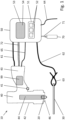
- the first cable 61 serves to supply the welding stud 20 with electrical current through the welding device 50.
- the second cable 62 serves to electrically connect the base 30 to the welding device 50 when the connection terminal 63 is clamped to the base 30.
- an electrical circuit is closed so that the welding stud 20 can be supplied with welding current from the welding device 50, which is designed as direct current or alternating current, for example.
- the welding gun 40 comprises a Fig.1 welding current contact element not shown.
- the gas supply line 71 and the gas hose 72 serve to supply a contact area between the welding stud 20 and the substrate 30 with a protective gas from the gas reservoir 70 in order to protect the contact area from oxidation by oxygen in the environment during a welding process.
- the gas reservoir 70, the gas supply line 71, the welding device 50, the gas hose 72 or the welding gun 40 comprises a valve (not shown), in particular a controllable valve.
- the welding device 50 has an input device 51 with actuating elements 52 and an output device 53 with a visual display element 54 and a wireless transmission unit.
- the input device 51 is used for the input of parameters of a welding process to be carried out with the welding device 10, such as the electrical voltage, current intensity, power and duration of the welding current, position and speed of the bolt and so on, by a user of the welding device 10.
- the output device 53 is used to output information, such as information about parameters of the welding process, information about recorded emissions of the welding process or other variables, information about a quality of the welding process, information about measures to improve the welding process, information about recorded properties of the welding bolt or information derived from the aforementioned variables, and/or recommendations or instructions for cleaning and/or maintaining the welding device 10, in particular the welding gun 40, to the user.
- the communication line 65 is used for communication between the welding gun 40, in particular a Fig.1 not shown control device of the welding gun 40, and the welding device 50, in particular the control device and/or the input device 51 and/or the output device 53.
- This communication enables, for example, an exchange of information about the parameters of a welding process in order to achieve or facilitate, for example, a synchronization of the welding current with a movement of the welding stud 20.
- the communication between the welding gun and the welding device takes place wirelessly, by radio or by means of the first electrical cable that carries the welding current.
- the welding gun 40 has a housing 42 with a mouth 46, from which a handle 43 with the trigger switch 41 protrudes.
- the welding gun 40 also has a Stud holder 44, on which the welding stud 20 is held during a welding process.
- the stud holder comprises, for example, two, three, four or more springy arms (not shown in detail), between which the welding stud 20 is inserted and held by means of a clamp fit.
- the welding gun 40 also has a welding current contact element for applying a welding current to the welding stud 20, which is integrated into the stud holder 44, for example in the form of one or more of the springy arms.
- the welding gun 40 also has a control device 99 for controlling the various components and devices of the welding gun and the welding device 50.
- the control device 99 is provided for controlling one or more parameters of the welding process.
- the control device 99 comprises various electronic components, such as one or more microprocessors, one or more temporary or permanent data memories and the like.
- the welding gun 40 further comprises a bolt lifting device designed as a first lifting magnet, which moves the bolt holder 44 with a force away from the muzzle 46 to the rear (in Fig.1 upwards) when the bolt lifting device is activated.
- the control device 99 communicates with the bolt lifting device via a signal line (not shown) in order to control the bolt lifting device, in particular to activate and deactivate it.
- the welding gun 40 further comprises a stud immersion device designed as a spring element or as a second lifting magnet, which pushes the stud holder 44 forwards (in Fig.1 downwards) when the bolt immersion device is activated.
- the control device 99 communicates with the bolt immersion device via a signal line (not shown) in order to control the bolt immersion device, in particular to activate and deactivate it.
- the bolt immersion device is designed as a spring element, this spring element is preferably tensioned when the bolt holder is moved backwards by the bolt lifting device, so that the spring element moves the bolt holder forwards as soon as the bolt lifting device is deactivated.
- the substrate 30 and the bolt 20 are first made available.
- a user enters information via the input device, for example about desired parameters of the following welding process.
- the welding stud 20 is subjected to a welding current between the welding stud 20 and the substrate 30 by the welding device 50 by means of the first cable 61 and the second cable 62.
- the welding stud 20 is lifted off the substrate by means of the stud lifting device while maintaining the welding current flowing between the welding stud 20 and the substrate 30, whereby an arc forms between the welding stud 20 and the substrate 30.
- a material of the welding stud 20 and/or the substrate 30 is then partially liquefied.
- the welding stud 20 is immersed in the liquefied material of the welding stud 20 or the substrate 30 by means of the stud immersion device. Thereafter, the liquefied material of the welding stud 20 or the substrate 30 solidifies, so that the welding stud 20 is firmly bonded to the substrate 30.
- a welding device 100 is shown schematically in a longitudinal section, which is intended for welding a welding stud 120 along a welding axis 105 in a welding direction 110 to a substrate 130.
- the welding device 100 is designed as a welding gun defining the welding direction 110.
- the welding device 100 has a holding device 144 designed as a stud holder with an outer diameter dA, which has a stud receptacle 121 with an inner diameter dl for holding the welding stud 120 during a welding process, into which the welding stud 120 can be inserted and is preferably held in a clamped manner.
- a contact surface 125 of the welding stud 120 contacts the substrate 130 before and/or during the welding process.
- the welding device 100 comprises a schematically illustrated housing 101 with a handle (not shown) and a trigger switch (not shown) as well as a protective gas bell 140, which is intended to be flushed with protective gas in order to suppress or completely prevent oxidation of the weld melt with oxygen from the ambient air.
- the protective gas bell 140 has a protective gas supply line, which comprises a plurality of first connecting channels 150 arranged in a ring around the welding axis 105.
- a protective gas hose 145 or the like can be connected to the protective gas supply line to supply the protective gas bell 140.
- Each of the first connecting channels 150 running axially with respect to the welding axis 105 opens into a main chamber 141 of the protective gas bell 140 with an inlet opening 160, so that the inlet openings 160 also are arranged in a ring around the welding axis 105 and together form a protective gas inlet.
- the protective gas inlet comprises a single ring-shaped inlet opening that runs around the welding axis.
- the protective gas bell 140 has a plurality of outlet openings 170 that are also arranged in a ring around the welding axis, which lead radially through the protective gas bell 140 outwards into the environment with respect to the welding axis 105 and form a protective gas outlet.
- the outlet openings 170 are each arranged offset from the inlet openings 160.
- the shielding gas bell 140 has a mouth 180 pointing in the welding direction 110, which has a mouth diameter dM transverse to the welding direction 110.
- the shielding gas inlet namely the inlet openings 160, have an inlet distance aE to the mouth 180 opposite to the welding direction 110.
- the shielding gas outlet namely the outlet openings 170, have an outlet distance aA to the mouth 180 opposite to the welding direction 110.
- the outlet distance aA is approximately half as large as the difference between the orifice diameter dM and the inner diameter dl, i.e. approximately as large as a radial distance x between the welding stud 120 and the shielding gas bell 140.
- the outlet distance aA is larger than the inlet distance aE.
- a toroidal flow pattern is thus formed, which is arranged radially symmetrically around the welding axis 105 and causes a uniform and effective flushing of the welding point at the welding stud 120 with shielding gas.
- Ambient air which for example comes from the narrow gap between the holding device 144 and the shielding gas bell (in Fig. 2 above the outlet openings 170) only slowly escapes, is carried along by the flow through the outlet openings 170 and shielded from the weld point.
- a welding device 200 is shown schematically in a longitudinal section, which is largely identical to the welding device 100 ( Fig. 2 ) matches. Same Elements have the same reference numerals.
- the welding device 200 differs from the welding device 100 in particular in the arrangement of the inlet openings 160 and the outlet openings 170.
- the outlet distance aA is approximately half as large as a difference between the mouth diameter dM and the outside diameter dA, i.e. approximately as large as a radial distance y between the holding device 144 and the shielding gas bell 140.
- the outlet distance aA is smaller than the inlet distance aE, but more than half as large as the inlet distance aE.
- the outlet openings 170 are each arranged offset from the inlet openings 160, so that an interaction between the incoming and outgoing shielding gas is reduced.
Landscapes
- Engineering & Computer Science (AREA)
- Physics & Mathematics (AREA)
- Plasma & Fusion (AREA)
- Mechanical Engineering (AREA)
- Arc Welding In General (AREA)
Claims (9)
- Dispositif de soudage (100, 200), en particulier un pistolet de soudage, destiné à souder un boulon de soudage (120) à un substrat (130) le long d'un axe de soudage dans une direction de soudage, ledit dispositif de soudage comprenant une cloche à gaz de protection (140) comprenant une entrée de gaz de protection (150) disposée annulairement autour l'axe de soudage, une sortie de gaz de protection (170), et une embouchure (180) orientée dans la direction de soudage, l'embouchure ayant un diamètre d'embouchure (dM) transversalement à la direction de soudage, l'entrée de gaz de protection présentant une distance d'entrée (aE) à l'embouchure dans une direction opposée à la direction de soudage, la sortie de gaz de protection présentant une distance de sortie (aA) à l'embouchure dans une direction opposée à la direction de soudage, ledit dispositif de soudage comprenant en outre un dispositif de retenue (144) destiné à maintenir le boulon de soudage (120) à l'intérieur de la cloche de gaz de protection pendant un processus de soudage, le dispositif de retenue ayant un diamètre extérieur (dA) et comportant un logement de boulon d'un diamètre intérieur (dl), caractérisé en ce que la distance de sortie (170) est égale à au moins la moitié d'une différence entre le diamètre d'embouchure (dM) et le diamètre extérieur (dA) ou est au moins aussi grande que la distance d'entrée (aE).
- Dispositif de soudage selon la revendication 1, la distance de sortie étant égale à au moins la moitié de la différence entre le diamètre de l'embouchure et le diamètre intérieur ou étant au moins aussi grande que la distance d'entrée.
- Dispositif de soudage selon l'une des revendications précédentes, la distance de sortie étant égale à au moins la moitié de la différence entre le diamètre de l'embouchure et le diamètre extérieur et étant au moins aussi grande que la moitié de la distance d'entrée.
- Dispositif de soudage selon l'une des revendications précédentes, l'entée de gaz de protection étant dirigée vers une zone radialement extérieure de l'embouchure afin de générer un écoulement de gaz de protection le long de l'embouchure radialement vers l'axe de réglage, lorsque l'embouchure est recouverte.
- Dispositif de soudage selon l'une des revendications précédentes, l'entrée de gaz de protection comprenant une ouverture d'entrée annulaire s'étendant autour de l'axe de soudage.
- Dispositif de soudage selon l'une des revendications précédentes, l'entrée de gaz de protection comprenant un grand nombre d'ouvertures d'entrée disposées annulairement autour de l'axe de soudage.
- Dispositif de soudage selon l'une des revendications précédentes, la sortie de gaz de protection comprenant un grand nombre d'ouvertures de sortie disposées annulairement autour de l'axe de soudage.
- Dispositif de soudage selon l'une des revendications précédentes, la sortie de gaz de protection menant radialement vers l'extérieur à travers la cloche de gaz de protection jusque dans l'environnement par rapport à l'axe de soudage.
- Dispositif de soudage selon l'une des revendications précédentes, la sortie de gaz de protection étant disposée de manière décalée par rapport à l'entrée de gaz de protection dans une direction transversale à l'axe de soudage.
Applications Claiming Priority (2)
| Application Number | Priority Date | Filing Date | Title |
|---|---|---|---|
| EP20214831.8A EP4015131A1 (fr) | 2020-12-17 | 2020-12-17 | Dispositif de soudage de goujon avbec répartition du gaz |
| PCT/EP2021/083777 WO2022128475A1 (fr) | 2020-12-17 | 2021-12-01 | Dispositif de soudage conçu pour souder un goujon à souder, présentant une fonction de distribution de gaz |
Publications (3)
| Publication Number | Publication Date |
|---|---|
| EP4263106A1 EP4263106A1 (fr) | 2023-10-25 |
| EP4263106B1 true EP4263106B1 (fr) | 2024-09-25 |
| EP4263106C0 EP4263106C0 (fr) | 2024-09-25 |
Family
ID=73855235
Family Applications (2)
| Application Number | Title | Priority Date | Filing Date |
|---|---|---|---|
| EP20214831.8A Withdrawn EP4015131A1 (fr) | 2020-12-17 | 2020-12-17 | Dispositif de soudage de goujon avbec répartition du gaz |
| EP21830956.5A Active EP4263106B1 (fr) | 2020-12-17 | 2021-12-01 | Dispositif de soudage de goujon avec répartition du gaz |
Family Applications Before (1)
| Application Number | Title | Priority Date | Filing Date |
|---|---|---|---|
| EP20214831.8A Withdrawn EP4015131A1 (fr) | 2020-12-17 | 2020-12-17 | Dispositif de soudage de goujon avbec répartition du gaz |
Country Status (6)
| Country | Link |
|---|---|
| US (1) | US20240042540A1 (fr) |
| EP (2) | EP4015131A1 (fr) |
| JP (1) | JP7606614B2 (fr) |
| KR (1) | KR20230117370A (fr) |
| CN (1) | CN116745058A (fr) |
| WO (1) | WO2022128475A1 (fr) |
Families Citing this family (1)
| Publication number | Priority date | Publication date | Assignee | Title |
|---|---|---|---|---|
| CN116604148A (zh) * | 2023-06-21 | 2023-08-18 | 深圳市鸿栢科技实业有限公司 | 气保螺柱焊枪的气保结构 |
Family Cites Families (8)
| Publication number | Priority date | Publication date | Assignee | Title |
|---|---|---|---|---|
| US2790066A (en) * | 1954-08-13 | 1957-04-23 | Gregory Ind Inc | Stud welder |
| DE102006039842B4 (de) * | 2005-08-27 | 2009-04-09 | Ford Global Technologies, LLC, Dearborn | Verfahren und Vorrichtung zum Verschweißen eines Bauteils mit einem Werkstück nach dem Lichtbogenverfahren unter Schutzgas |
| WO2008011908A1 (fr) * | 2006-07-28 | 2008-01-31 | Hbs Bolzenschweiss-Systeme Gmbh & Co. Kg | Dispositif pour souder un élément de soudage annulaire au moyen d'un gaz de formation acheminé à travers ledit élément de soudage |
| US9144148B2 (en) * | 2013-07-25 | 2015-09-22 | Hypertherm, Inc. | Devices for gas cooling plasma arc torches and related systems and methods |
| DE202016100923U1 (de) * | 2016-02-22 | 2016-03-02 | Bolzenschweißtechnik Heinz Soyer GmbH | Schweißvorrichtung mit Schutzgasführung |
| EP3498411A1 (fr) * | 2017-12-18 | 2019-06-19 | HILTI Aktiengesellschaft | Pistolet de soudage de goujons |
| EP3501720A1 (fr) * | 2017-12-20 | 2019-06-26 | HILTI Aktiengesellschaft | Pistolet de soudage de goujons et procédé |
| JP6860260B2 (ja) * | 2018-12-25 | 2021-04-14 | 株式会社ムラタ溶研 | スポット溶接用の狭窄ノズル付きtig溶接トーチ及びこれに用いられる電極用ノズル |
-
2020
- 2020-12-17 EP EP20214831.8A patent/EP4015131A1/fr not_active Withdrawn
-
2021
- 2021-12-01 US US18/266,637 patent/US20240042540A1/en active Pending
- 2021-12-01 WO PCT/EP2021/083777 patent/WO2022128475A1/fr not_active Ceased
- 2021-12-01 CN CN202180084307.2A patent/CN116745058A/zh active Pending
- 2021-12-01 JP JP2023537245A patent/JP7606614B2/ja active Active
- 2021-12-01 EP EP21830956.5A patent/EP4263106B1/fr active Active
- 2021-12-01 KR KR1020237021038A patent/KR20230117370A/ko active Pending
Also Published As
| Publication number | Publication date |
|---|---|
| EP4015131A1 (fr) | 2022-06-22 |
| JP7606614B2 (ja) | 2024-12-25 |
| KR20230117370A (ko) | 2023-08-08 |
| EP4263106A1 (fr) | 2023-10-25 |
| EP4263106C0 (fr) | 2024-09-25 |
| WO2022128475A1 (fr) | 2022-06-23 |
| CN116745058A (zh) | 2023-09-12 |
| JP2023554463A (ja) | 2023-12-27 |
| US20240042540A1 (en) | 2024-02-08 |
Similar Documents
| Publication | Publication Date | Title |
|---|---|---|
| EP3727737A2 (fr) | Système de fixation | |
| EP3157705A1 (fr) | Procédé de soudage par résistance par points d'un matériau stratifié et dispositif associé | |
| EP1575734B1 (fr) | Couvercle protecteur con u pour un tuyau de contact d'un chalumeau a souder et chalumeau a souder pourvu de ce couvercle protecteur | |
| EP4263106B1 (fr) | Dispositif de soudage de goujon avec répartition du gaz | |
| EP0663259B1 (fr) | Appareil de soudage pour goujons de section annulaire | |
| EP3694673B1 (fr) | Procédé de fixation | |
| EP4263107B1 (fr) | Dispositif de soudage de goujon sur une pièce avec répartition de gaz | |
| DE2813804A1 (de) | Plasmabogen schweiss- und schneidgeraet | |
| DE3524034A1 (de) | Vorrichtung zum plasmaschneiden von metallischen werkstuecken | |
| WO2019053055A1 (fr) | Chalumeau tig de soudage, brasage ou revêtement | |
| EP3694675B1 (fr) | Boulon et dispositif de fixation | |
| EP3898056B1 (fr) | Dispositif de soudage | |
| DE102004060389A1 (de) | Verfahren zum Bolzenschweißen von Schweißenteilen mit länglich ausgedehnter Schweißfläche | |
| WO2023099228A1 (fr) | Procédé de fixation | |
| DE10143220C1 (de) | Bolzenschweißen mit magnetischer Lichtbogenrotation | |
| EP3694672B1 (fr) | Dispositif de soudage et procédé de soudage | |
| DE102009005082A1 (de) | Vorrichtung und Verfahren zum Lichtbogendrahtspritzen | |
| DE102019126651A1 (de) | Lichtbogenbrenner und Lichtbogen-Drahtspritzeinrichtung | |
| EP3501720A1 (fr) | Pistolet de soudage de goujons et procédé | |
| WO2019072627A1 (fr) | Goujon à souder et pistolet de soudage | |
| WO2019072731A1 (fr) | Procédé de fixation | |
| WO2020011476A1 (fr) | Procédé de soudage de billes | |
| DE102024130497A1 (de) | Metallschutzgasfügevorrichtung | |
| DE102011114406A1 (de) | Plasmaspritzgerät | |
| DE9309141U1 (de) | Düse zur Bearbeitung eines Werkstücks |
Legal Events
| Date | Code | Title | Description |
|---|---|---|---|
| STAA | Information on the status of an ep patent application or granted ep patent |
Free format text: STATUS: UNKNOWN |
|
| STAA | Information on the status of an ep patent application or granted ep patent |
Free format text: STATUS: THE INTERNATIONAL PUBLICATION HAS BEEN MADE |
|
| PUAI | Public reference made under article 153(3) epc to a published international application that has entered the european phase |
Free format text: ORIGINAL CODE: 0009012 |
|
| STAA | Information on the status of an ep patent application or granted ep patent |
Free format text: STATUS: REQUEST FOR EXAMINATION WAS MADE |
|
| 17P | Request for examination filed |
Effective date: 20230717 |
|
| AK | Designated contracting states |
Kind code of ref document: A1 Designated state(s): AL AT BE BG CH CY CZ DE DK EE ES FI FR GB GR HR HU IE IS IT LI LT LU LV MC MK MT NL NO PL PT RO RS SE SI SK SM TR |
|
| DAV | Request for validation of the european patent (deleted) | ||
| DAX | Request for extension of the european patent (deleted) | ||
| GRAP | Despatch of communication of intention to grant a patent |
Free format text: ORIGINAL CODE: EPIDOSNIGR1 |
|
| STAA | Information on the status of an ep patent application or granted ep patent |
Free format text: STATUS: GRANT OF PATENT IS INTENDED |
|
| GRAS | Grant fee paid |
Free format text: ORIGINAL CODE: EPIDOSNIGR3 |
|
| INTG | Intention to grant announced |
Effective date: 20240717 |
|
| GRAA | (expected) grant |
Free format text: ORIGINAL CODE: 0009210 |
|
| STAA | Information on the status of an ep patent application or granted ep patent |
Free format text: STATUS: THE PATENT HAS BEEN GRANTED |
|
| AK | Designated contracting states |
Kind code of ref document: B1 Designated state(s): AL AT BE BG CH CY CZ DE DK EE ES FI FR GB GR HR HU IE IS IT LI LT LU LV MC MK MT NL NO PL PT RO RS SE SI SK SM TR |
|
| REG | Reference to a national code |
Ref country code: GB Ref legal event code: FG4D Free format text: NOT ENGLISH |
|
| REG | Reference to a national code |
Ref country code: CH Ref legal event code: EP |
|
| REG | Reference to a national code |
Ref country code: DE Ref legal event code: R096 Ref document number: 502021005279 Country of ref document: DE |
|
| REG | Reference to a national code |
Ref country code: IE Ref legal event code: FG4D Free format text: LANGUAGE OF EP DOCUMENT: GERMAN |
|
| U01 | Request for unitary effect filed |
Effective date: 20240930 |
|
| U07 | Unitary effect registered |
Designated state(s): AT BE BG DE DK EE FI FR IT LT LU LV MT NL PT RO SE SI Effective date: 20241024 |
|
| PG25 | Lapsed in a contracting state [announced via postgrant information from national office to epo] |
Ref country code: NO Free format text: LAPSE BECAUSE OF FAILURE TO SUBMIT A TRANSLATION OF THE DESCRIPTION OR TO PAY THE FEE WITHIN THE PRESCRIBED TIME-LIMIT Effective date: 20241225 |
|
| PG25 | Lapsed in a contracting state [announced via postgrant information from national office to epo] |
Ref country code: GR Free format text: LAPSE BECAUSE OF FAILURE TO SUBMIT A TRANSLATION OF THE DESCRIPTION OR TO PAY THE FEE WITHIN THE PRESCRIBED TIME-LIMIT Effective date: 20241226 |
|
| PG25 | Lapsed in a contracting state [announced via postgrant information from national office to epo] |
Ref country code: RS Free format text: LAPSE BECAUSE OF FAILURE TO SUBMIT A TRANSLATION OF THE DESCRIPTION OR TO PAY THE FEE WITHIN THE PRESCRIBED TIME-LIMIT Effective date: 20241225 |
|
| PG25 | Lapsed in a contracting state [announced via postgrant information from national office to epo] |
Ref country code: RS Free format text: LAPSE BECAUSE OF FAILURE TO SUBMIT A TRANSLATION OF THE DESCRIPTION OR TO PAY THE FEE WITHIN THE PRESCRIBED TIME-LIMIT Effective date: 20241225 Ref country code: NO Free format text: LAPSE BECAUSE OF FAILURE TO SUBMIT A TRANSLATION OF THE DESCRIPTION OR TO PAY THE FEE WITHIN THE PRESCRIBED TIME-LIMIT Effective date: 20241225 Ref country code: GR Free format text: LAPSE BECAUSE OF FAILURE TO SUBMIT A TRANSLATION OF THE DESCRIPTION OR TO PAY THE FEE WITHIN THE PRESCRIBED TIME-LIMIT Effective date: 20241226 |
|
| U20 | Renewal fee for the european patent with unitary effect paid |
Year of fee payment: 4 Effective date: 20241227 |
|
| PG25 | Lapsed in a contracting state [announced via postgrant information from national office to epo] |
Ref country code: IS Free format text: LAPSE BECAUSE OF FAILURE TO SUBMIT A TRANSLATION OF THE DESCRIPTION OR TO PAY THE FEE WITHIN THE PRESCRIBED TIME-LIMIT Effective date: 20250125 |
|
| PG25 | Lapsed in a contracting state [announced via postgrant information from national office to epo] |
Ref country code: SM Free format text: LAPSE BECAUSE OF FAILURE TO SUBMIT A TRANSLATION OF THE DESCRIPTION OR TO PAY THE FEE WITHIN THE PRESCRIBED TIME-LIMIT Effective date: 20240925 |
|
| PG25 | Lapsed in a contracting state [announced via postgrant information from national office to epo] |
Ref country code: ES Free format text: LAPSE BECAUSE OF FAILURE TO SUBMIT A TRANSLATION OF THE DESCRIPTION OR TO PAY THE FEE WITHIN THE PRESCRIBED TIME-LIMIT Effective date: 20240925 |
|
| PG25 | Lapsed in a contracting state [announced via postgrant information from national office to epo] |
Ref country code: CZ Free format text: LAPSE BECAUSE OF FAILURE TO SUBMIT A TRANSLATION OF THE DESCRIPTION OR TO PAY THE FEE WITHIN THE PRESCRIBED TIME-LIMIT Effective date: 20240925 Ref country code: PL Free format text: LAPSE BECAUSE OF FAILURE TO SUBMIT A TRANSLATION OF THE DESCRIPTION OR TO PAY THE FEE WITHIN THE PRESCRIBED TIME-LIMIT Effective date: 20240925 |
|
| PG25 | Lapsed in a contracting state [announced via postgrant information from national office to epo] |
Ref country code: SK Free format text: LAPSE BECAUSE OF FAILURE TO SUBMIT A TRANSLATION OF THE DESCRIPTION OR TO PAY THE FEE WITHIN THE PRESCRIBED TIME-LIMIT Effective date: 20240925 |
|
| PG25 | Lapsed in a contracting state [announced via postgrant information from national office to epo] |
Ref country code: MC Free format text: LAPSE BECAUSE OF FAILURE TO SUBMIT A TRANSLATION OF THE DESCRIPTION OR TO PAY THE FEE WITHIN THE PRESCRIBED TIME-LIMIT Effective date: 20240925 |
|
| REG | Reference to a national code |
Ref country code: CH Ref legal event code: PL |
|
| PLBE | No opposition filed within time limit |
Free format text: ORIGINAL CODE: 0009261 |
|
| STAA | Information on the status of an ep patent application or granted ep patent |
Free format text: STATUS: NO OPPOSITION FILED WITHIN TIME LIMIT |
|
| 26N | No opposition filed |
Effective date: 20250626 |
|
| PG25 | Lapsed in a contracting state [announced via postgrant information from national office to epo] |
Ref country code: CH Free format text: LAPSE BECAUSE OF NON-PAYMENT OF DUE FEES Effective date: 20241231 |
|
| PG25 | Lapsed in a contracting state [announced via postgrant information from national office to epo] |
Ref country code: IE Free format text: LAPSE BECAUSE OF NON-PAYMENT OF DUE FEES Effective date: 20241201 |
|
| PG25 | Lapsed in a contracting state [announced via postgrant information from national office to epo] |
Ref country code: HR Free format text: LAPSE BECAUSE OF FAILURE TO SUBMIT A TRANSLATION OF THE DESCRIPTION OR TO PAY THE FEE WITHIN THE PRESCRIBED TIME-LIMIT Effective date: 20240925 |
|
| U20 | Renewal fee for the european patent with unitary effect paid |
Year of fee payment: 5 Effective date: 20251230 |
|
| PG25 | Lapsed in a contracting state [announced via postgrant information from national office to epo] |
Ref country code: CY Free format text: LAPSE BECAUSE OF FAILURE TO SUBMIT A TRANSLATION OF THE DESCRIPTION OR TO PAY THE FEE WITHIN THE PRESCRIBED TIME-LIMIT; INVALID AB INITIO Effective date: 20211201 |