EP4263993B1 - Anordnung zur führung eines bewegbaren möbelteils - Google Patents
Anordnung zur führung eines bewegbaren möbelteils Download PDFInfo
- Publication number
- EP4263993B1 EP4263993B1 EP21830924.3A EP21830924A EP4263993B1 EP 4263993 B1 EP4263993 B1 EP 4263993B1 EP 21830924 A EP21830924 A EP 21830924A EP 4263993 B1 EP4263993 B1 EP 4263993B1
- Authority
- EP
- European Patent Office
- Prior art keywords
- furniture part
- guide
- movable furniture
- movable
- furniture
- Prior art date
- Legal status (The legal status is an assumption and is not a legal conclusion. Google has not performed a legal analysis and makes no representation as to the accuracy of the status listed.)
- Active
Links
Images





Classifications
-
- E—FIXED CONSTRUCTIONS
- E05—LOCKS; KEYS; WINDOW OR DOOR FITTINGS; SAFES
- E05D—HINGES OR SUSPENSION DEVICES FOR DOORS, WINDOWS OR WINGS
- E05D15/00—Suspension arrangements for wings
- E05D15/06—Suspension arrangements for wings for wings sliding horizontally more or less in their own plane
- E05D15/0621—Details, e.g. suspension or supporting guides
-
- E—FIXED CONSTRUCTIONS
- E05—LOCKS; KEYS; WINDOW OR DOOR FITTINGS; SAFES
- E05D—HINGES OR SUSPENSION DEVICES FOR DOORS, WINDOWS OR WINGS
- E05D15/00—Suspension arrangements for wings
- E05D15/26—Suspension arrangements for wings for folding wings
- E05D15/264—Suspension arrangements for wings for folding wings for bi-fold wings
-
- E—FIXED CONSTRUCTIONS
- E05—LOCKS; KEYS; WINDOW OR DOOR FITTINGS; SAFES
- E05D—HINGES OR SUSPENSION DEVICES FOR DOORS, WINDOWS OR WINGS
- E05D15/00—Suspension arrangements for wings
- E05D15/56—Suspension arrangements for wings with successive different movements
- E05D15/58—Suspension arrangements for wings with successive different movements with both swinging and sliding movements
-
- E—FIXED CONSTRUCTIONS
- E06—DOORS, WINDOWS, SHUTTERS, OR ROLLER BLINDS IN GENERAL; LADDERS
- E06B—FIXED OR MOVABLE CLOSURES FOR OPENINGS IN BUILDINGS, VEHICLES, FENCES OR LIKE ENCLOSURES IN GENERAL, e.g. DOORS, WINDOWS, BLINDS, GATES
- E06B3/00—Window sashes, door leaves, or like elements for closing wall or like openings; Layout of fixed or moving closures, e.g. windows in wall or like openings; Features of rigidly-mounted outer frames relating to the mounting of wing frames
- E06B3/32—Arrangements of wings characterised by the manner of movement; Arrangements of movable wings in openings; Features of wings or frames relating solely to the manner of movement of the wing
- E06B3/50—Arrangements of wings characterised by the manner of movement; Arrangements of movable wings in openings; Features of wings or frames relating solely to the manner of movement of the wing with more than one kind of movement
- E06B3/5045—Arrangements of wings characterised by the manner of movement; Arrangements of movable wings in openings; Features of wings or frames relating solely to the manner of movement of the wing with more than one kind of movement specially adapted for furniture
-
- E—FIXED CONSTRUCTIONS
- E05—LOCKS; KEYS; WINDOW OR DOOR FITTINGS; SAFES
- E05D—HINGES OR SUSPENSION DEVICES FOR DOORS, WINDOWS OR WINGS
- E05D15/00—Suspension arrangements for wings
- E05D15/56—Suspension arrangements for wings with successive different movements
- E05D15/58—Suspension arrangements for wings with successive different movements with both swinging and sliding movements
- E05D2015/586—Suspension arrangements for wings with successive different movements with both swinging and sliding movements with travelling hinge parts
-
- E—FIXED CONSTRUCTIONS
- E05—LOCKS; KEYS; WINDOW OR DOOR FITTINGS; SAFES
- E05Y—INDEXING SCHEME ASSOCIATED WITH SUBCLASSES E05D AND E05F, RELATING TO CONSTRUCTION ELEMENTS, ELECTRIC CONTROL, POWER SUPPLY, POWER SIGNAL OR TRANSMISSION, USER INTERFACES, MOUNTING OR COUPLING, DETAILS, ACCESSORIES, AUXILIARY OPERATIONS NOT OTHERWISE PROVIDED FOR, APPLICATION THEREOF
- E05Y2201/00—Constructional elements; Accessories therefor
- E05Y2201/60—Suspension or transmission members; Accessories therefor
- E05Y2201/606—Accessories therefor
- E05Y2201/62—Synchronisation of suspension or transmission members
-
- E—FIXED CONSTRUCTIONS
- E05—LOCKS; KEYS; WINDOW OR DOOR FITTINGS; SAFES
- E05Y—INDEXING SCHEME ASSOCIATED WITH SUBCLASSES E05D AND E05F, RELATING TO CONSTRUCTION ELEMENTS, ELECTRIC CONTROL, POWER SUPPLY, POWER SIGNAL OR TRANSMISSION, USER INTERFACES, MOUNTING OR COUPLING, DETAILS, ACCESSORIES, AUXILIARY OPERATIONS NOT OTHERWISE PROVIDED FOR, APPLICATION THEREOF
- E05Y2201/00—Constructional elements; Accessories therefor
- E05Y2201/60—Suspension or transmission members; Accessories therefor
- E05Y2201/622—Suspension or transmission members elements
- E05Y2201/624—Arms
-
- E—FIXED CONSTRUCTIONS
- E05—LOCKS; KEYS; WINDOW OR DOOR FITTINGS; SAFES
- E05Y—INDEXING SCHEME ASSOCIATED WITH SUBCLASSES E05D AND E05F, RELATING TO CONSTRUCTION ELEMENTS, ELECTRIC CONTROL, POWER SUPPLY, POWER SIGNAL OR TRANSMISSION, USER INTERFACES, MOUNTING OR COUPLING, DETAILS, ACCESSORIES, AUXILIARY OPERATIONS NOT OTHERWISE PROVIDED FOR, APPLICATION THEREOF
- E05Y2201/00—Constructional elements; Accessories therefor
- E05Y2201/60—Suspension or transmission members; Accessories therefor
- E05Y2201/622—Suspension or transmission members elements
- E05Y2201/644—Flexible elongated pulling elements
- E05Y2201/654—Cables
-
- E—FIXED CONSTRUCTIONS
- E05—LOCKS; KEYS; WINDOW OR DOOR FITTINGS; SAFES
- E05Y—INDEXING SCHEME ASSOCIATED WITH SUBCLASSES E05D AND E05F, RELATING TO CONSTRUCTION ELEMENTS, ELECTRIC CONTROL, POWER SUPPLY, POWER SIGNAL OR TRANSMISSION, USER INTERFACES, MOUNTING OR COUPLING, DETAILS, ACCESSORIES, AUXILIARY OPERATIONS NOT OTHERWISE PROVIDED FOR, APPLICATION THEREOF
- E05Y2201/00—Constructional elements; Accessories therefor
- E05Y2201/60—Suspension or transmission members; Accessories therefor
- E05Y2201/622—Suspension or transmission members elements
- E05Y2201/684—Rails; Tracks
-
- E—FIXED CONSTRUCTIONS
- E05—LOCKS; KEYS; WINDOW OR DOOR FITTINGS; SAFES
- E05Y—INDEXING SCHEME ASSOCIATED WITH SUBCLASSES E05D AND E05F, RELATING TO CONSTRUCTION ELEMENTS, ELECTRIC CONTROL, POWER SUPPLY, POWER SIGNAL OR TRANSMISSION, USER INTERFACES, MOUNTING OR COUPLING, DETAILS, ACCESSORIES, AUXILIARY OPERATIONS NOT OTHERWISE PROVIDED FOR, APPLICATION THEREOF
- E05Y2600/00—Mounting or coupling arrangements for elements provided for in this subclass
- E05Y2600/10—Adjustable
- E05Y2600/12—Adjustable by manual operation
-
- E—FIXED CONSTRUCTIONS
- E05—LOCKS; KEYS; WINDOW OR DOOR FITTINGS; SAFES
- E05Y—INDEXING SCHEME ASSOCIATED WITH SUBCLASSES E05D AND E05F, RELATING TO CONSTRUCTION ELEMENTS, ELECTRIC CONTROL, POWER SUPPLY, POWER SIGNAL OR TRANSMISSION, USER INTERFACES, MOUNTING OR COUPLING, DETAILS, ACCESSORIES, AUXILIARY OPERATIONS NOT OTHERWISE PROVIDED FOR, APPLICATION THEREOF
- E05Y2900/00—Application of doors, windows, wings or fittings thereof
- E05Y2900/20—Application of doors, windows, wings or fittings thereof for furniture, e.g. cabinets
- E05Y2900/212—Doors disappearing in pockets in the furniture body
Definitions
- the invention relates to an arrangement for guiding a movable furniture part, preferably a sliding door or folding sliding door, on a fixed furniture part, preferably a furniture body, with the features of the preamble of claim 1.
- the invention further relates to a piece of furniture with such an arrangement.
- Arrangements according to the preamble of claim 1 are already known.
- a disadvantage of such solutions according to the prior art is that the movable furniture part is only guided via the carrier on the at least one guide system. A movement of the carrier - and thus also of the movable furniture part - along the at least one guide system can be made difficult or blocked due to the inadequate guidance of the movable furniture part by the movable furniture part. It is also possible that the movable and/or the fixed furniture part is or are damaged by such a movement.
- the US 2015/008811 A1 therefore proposes a piece of furniture with a folding sliding door which can be inserted into a furniture body, whereby the folding sliding door is guided via a guide element in a groove in the depth direction of the furniture body.
- the object of the present invention is to avoid the described disadvantages according to the prior art and to provide an arrangement which is improved compared to the prior art for guiding a movable furniture part, preferably a sliding door or folding sliding door, on a fixed furniture part, preferably a furniture body, and a piece of furniture with at least one such arrangement.
- the movable furniture part has a guide device separate from the at least one guide system for directly guiding the movable furniture part on the fixed furniture part.
- the movable furniture part is therefore not only guided indirectly via the support, but also directly via the separate guide device on the fixed furniture part.
- the support - and thus also the movable furniture part - moves along at least one guide system, the movable furniture part is guided in such a way that a smooth movement sequence is ensured.
- the arrangement comprises at least one adjustment device by means of which at least one Part of the guide device is adjustable relative to the fixed furniture part, preferably in a direction normal to a longitudinal extension of the at least one guide system.
- Such an adjustment device enables the guide device to be adjusted, especially subsequently, to given or changing conditions.
- the guide device can be adjusted using the adjustment device so that the movable furniture part is guided parallel to the at least one guide system when the carrier - and thus also the movable furniture part - moves along the at least one guide system.
- the adjustment device has an actuating element by means of which the adjustment device can be actuated, preferably wherein the actuating element is designed in the form of a screw. This represents a simple possibility for actuating the adjustment device.
- the adjustment device has a bearing device on which at least a part of the guide device is mounted, wherein the bearing device is movably mounted in a recess of a connecting element, preferably wherein the connecting element is arranged on the fixed furniture part (3).
- a piece of furniture according to the invention is provided with at least one fixed furniture part, at least one movable furniture part and at least one arrangement for guiding the movable furniture part on the fixed furniture part, preferably wherein the furniture comprises a shaft-shaped cavity in which the at least one movable furniture part can be arranged.
- the guide device comprises at least one groove and at least one guide element that partially engages in the at least one groove. This represents an uncomplicated and cost-effective but at the same time stable possibility for implementing a guide device.
- the at least one groove is arranged on the movable furniture part, preferably wherein the at least one groove extends over the entire length of an edge of the movable furniture part and that the at least one guide element is arranged on the fixed furniture part.
- the at least one groove is arranged on the fixed furniture part and that the at least one guide element is arranged on the movable furniture part, preferably wherein the at least one guide element extends over the entire length of an edge of the movable furniture part.
- At least one of the two variants ensures the best possible guidance of the movable furniture part on the fixed furniture part.
- the at least one groove or the at least one guide element extends over the entire length of an edge of the movable furniture part, this contributes to an even more stable and comprehensive guidance of the movable furniture part on the fixed furniture part.
- the movable furniture part is formed by a sliding door or folding sliding door, preferably wherein the sliding door or folding sliding door comprises only one door leaf.
- the arrangement may comprise a compensation device.
- the compensation device comprises a pivoting lever mechanism and/or a cable pulling device.
- Such a compensation device prevents the support from jamming on the at least one guide system if an overload occurs on the movable furniture part.
- the arrangement comprises at least two guide systems, preferably spaced vertically from each other, a ensures more stable guidance of the carrier on the guide systems.
- the movable furniture part comprises a frame, preferably made of an aluminum profile, and/or a cover, preferably made of glass.
- the movable furniture part enables a stable construction of the movable furniture part.
- the movable furniture part consists of an aluminum frame and a glass cover, this is also visually appealing for users.
- the profile can have the groove and/or the guide element. This is a cost-effective, uncomplicated and visually appealing way of implementing part of the guide device.
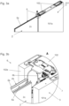
- a piece of furniture 100 with an arrangement according to the invention can be seen in a perspective view.
- the piece of furniture 100 comprises a fixed furniture part 3 and a movable furniture part 2 in the form of a folding sliding door with a door leaf.
- the door leaf is formed from a frame 2b (not visible) made of aluminum profiles and a cover 2c made of glass.
- the frame and cover can be any material that can be used for the frame and cover, such as wood, plastic or other metals. It can also be intended that the frame and cover are made of the same material or even that the frame and cover are made as one piece.
- the fixed furniture part 3 further comprises a cavity 101 which is delimited by side walls 101a.
- the movable furniture part 2 can be introduced into the cavity 101 at least in part.
- a piece of furniture 100 according to the invention has further furniture sections 103 with a folding sliding door 103a and a cavity 103b.
- These furniture sections 103 can be either ordinary furniture sections or furniture sections with arrangements according to the invention.
- the Figure 2a shows a perspective view of a part of a piece of furniture 100 according to the invention. It can be seen that the side walls 101a delimiting the cavity 101 are connected to one another via connecting elements 102. A guide device 6 can be seen in outline.
- the Figure 2b shows a perspective view of part of a piece of furniture 100 according to the invention, but without a side wall 101a.
- Two guide systems 4, 5 for guiding the support 8 on the fixed furniture part 3 can be seen.
- a movable furniture part 2 is pivotally mounted on the support 8 via hinges 8a.
- the pivot lever mechanism 9a comprises two pivot levers, whereby the longer of the two pivot levers is on the one hand on the fixed furniture part and on the other hand is pivotably mounted and displaceable essentially centrally on the support.
- the shorter of the two pivot levers is pivotably mounted in an upper area of the support and essentially centrally on the longer pivot lever.
- the cable pulling device 9b comprises a cable, each of which is arranged at its end on the support.
- the cable is connected to the fixed furniture part via pulleys.
- the Figure 3a shows a section of a perspective view of a part of a piece of furniture 100 according to the invention in a first position. It can be seen that the movable furniture part 2 is not yet arranged in the cavity 101.
- the Figure 3b is detail A of the Figure 3a shown.
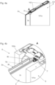
- the frame 2b has the groove 6a of the guide device 6.
- the groove 6a extends along an entire edge 2a of the frame 2b.
- the groove 6a is formed by the frame 2b.
- the groove 6a extends only partially along the edge 2a.
- the groove 6a can also be formed, for example, by a profile separate from the frame 2b.
- a connecting element 102 which connects the side walls 101a, can also be seen.
- the adjustment device 7 is arranged on the connecting element 102.
- a guide element 6b arranged on the adjustment device 7 can be adjusted via the adjustment device 7.
- the adjustment of the guide element 6b takes place along a normal to the side walls 101a.
- the guide element 6b is not yet in engagement with the groove 6a.
- the movable furniture part 2 or the frame 2b can be adjusted via the guide element 6b and the groove 6a by the adjustment device 7.
- the adjustment device 7 is not arranged on the connecting element 102 but, for example, via a separate fastening device on the fixed furniture part 3.
- the Figure 4a shows a section of a perspective view of a part of a piece of furniture 100 according to the invention in a first position. It can be seen that the movable furniture part 2 is arranged in parts in the cavity 101.
- the guide element 6b is now in engagement with the groove 6a, whereby the movable furniture part 2 is guided directly on the fixed furniture part 3.
- the Figure 5a shows for better understanding a section of a frontal view of a part of a furniture 100 according to the invention.
- the Figure 5b shows again the detail A of the Figure 5a .
- FIGS. 6a to 9b show various embodiments of frames 2b according to the invention, wherein the Figures 6a, 7a, 8a and 9a a perspective view of the frames 2b and the Figures 6b, 7b, 8b and 9b each show a corresponding sectional view.
- the frame 2b has the groove 6a.
- the frame 2b and the groove 6a are integrally formed with each other.
- the frame 2b is made of profiles, for example extruded profiles.
- the second embodiment according to the Figures 7a and 7b essentially corresponds to the first, but a cover 2c, for example made of glass, is additionally arranged on the frame 2b.
- the frame 2b has the guide element 6b.
- the frame 2b and the guide element 6b can be formed integrally with each other.
- the guide element 6b can also be formed by a separate part, for example made of plastic.
- the actuating element 7a is actuated, whereby the clamping via the locking elements 7b on the clamping area 7e is released.
- the bearing device 7c and thus the guide element 6b can now be adjusted.
- the bearing device 7c and thus the guide element 6b can be locked as already described.
Landscapes
- Engineering & Computer Science (AREA)
- Mechanical Engineering (AREA)
- Civil Engineering (AREA)
- Structural Engineering (AREA)
- Cabinets, Racks, Or The Like Of Rigid Construction (AREA)
- Support Devices For Sliding Doors (AREA)
- Coin-Freed Apparatuses For Hiring Articles (AREA)
Description
- Die Erfindung betrifft eine Anordnung zur Führung eines bewegbaren Möbelteils, vorzugsweise einer Schiebetür oder Falt-Schiebetür, an einem feststehenden Möbelteil, vorzugsweise einem Möbelkorpus, mit den Merkmalen des Oberbegriffs des Anspruchs 1. Die Erfindung betrifft weiterhin ein Möbel mit einer solchen Anordnung. Anordnungen gemäß dem Oberbegriff des Anspruchs 1 sind bereits bekannt. Nachteilig bei solchen Lösungen gemäß dem Stand der Technik ist, dass das bewegbare Möbelteil lediglich über den Träger an dem zumindest einen Führungssystem geführt ist. Eine Bewegung des Trägers - und somit auch des bewegbaren Möbelteils - entlang des zumindest einen Führungssystems kann aufgrund der unzureichenden Führung des bewegbaren Möbelteils durch das bewegbare Möbelteil erschwert oder blockiert werden. Es ist auch möglich, dass das bewegbare und/oder das feststehenden Möbelteil durch eine solche Bewegung beschädigt wird bzw. werden.
- Die
US 2015/008811 A1 schlägt deshalb ein Möbel mit einer Falt-Schiebtür, welche in einen Möbelkorpus einfahrbar ist, vor, wobei die Falt-Schiebtür über ein Führungselement in einer Nut in Tiefenrichtung des Möbelkorpus geführt ist. - Auch die
DE 298 09 193 U1 und dieKR 200 359 026 Y1 - Nachteilig bei diesen Anordnungen ist jedoch, dass keine Einstellmöglichkeiten für die Führung gegeben sind. Die Anordnung kann also beispielsweise nicht an veränderte Umgebungsbedingungen angepasst werden.
- Die Aufgabe der vorliegenden Erfindung besteht darin, die beschriebenen Nachteile gemäß dem Stand der Technik zu vermeiden und eine gegenüber dem Stand der Technik verbesserte Anordnung zur Führung eines bewegbaren Möbelteils, vorzugsweise einer Schiebetür oder FaltSchiebetür, an einem feststehenden Möbelteil, vorzugsweise einem Möbelkorpus, und ein Möbel mit zumindest einer solchen Anordnung anzugeben.
- Diese Aufgaben werden gelöst durch die Merkmale der unabhängigen Ansprüche 1 und 8.
- Erfindungsgemäß ist es demnach vorgesehen, dass das bewegbare Möbelteil eine vom zumindest einen Führungssystem gesonderte Führungsvorrichtung zur unmittelbaren Führung des bewegbaren Möbelteils an dem feststehenden Möbelteil aufweist.
- Somit ist das bewegbare Möbelteil nicht nur mittelbar über den Träger, sondern auch unmittelbar über die gesonderte Führungsvorrichtung an dem feststehenden Möbelteil geführt. Bei einer Bewegung des Trägers - und somit auch des bewegbaren Möbelteils - entlang des zumindest einen Führungssystems wird das bewegbare Möbelteil dadurch so geführt, dass ein reibungsloser Bewegungsablauf sichergestellt ist.
- Weiters ist vorgesehen, dass die Anordnung zumindest eine Einstellvorrichtung umfasst, mittels welcher zumindest ein Teil der Führungsvorrichtung relativ zu dem feststehenden Möbelteil, vorzugsweise in einer Richtung in einer Richtung normal auf eine Längserstreckung des zumindest einen Führungssystems, verstellbar ist.
- Eine solche Einstellvorrichtung ermöglicht dabei ein, vor allem auch nachträgliches, Einstellen der Führungsvorrichtung an gegebene oder sich ändernde Rahmenbedingungen. Insbesondere kann die Führungsvorrichtung mittels der Einstellvorrichtung so eingestellt werden, dass das bewegbare Möbelteil bei einer Bewegung des Trägers - und somit auch des bewegbaren Möbelteils - entlang des zumindest einen Führungssystems parallel zu dem zumindest einen Führungssystem geführt wird.
- Weiters ist vorgesehen, dass die Einstellvorrichtung ein Betätigungselement aufweist, mittels welchem die Einstellvorrichtung betätigbar ist, vorzugsweise wobei das Betätigungselement in Form einer Schraube ausgeführt ist. Dies stellt eine einfache Möglichkeit zur Betätigung der Einstellvorrichtung dar.
- Es ist auch vorgesehen, dass die Einstellvorrichtung eine Lagervorrichtung aufweist, an welcher zumindest ein Teil der Führungsvorrichtung gelagert ist, wobei die Lagervorrichtung in einer Ausnehmung eines Verbindungselements bewegbar gelagert ist, vorzugsweise wobei das Verbindungselement an dem feststehenden Möbelteil (3) angeordnet ist.
- Es ist weiters ein erfindungsgemäßes Möbel mit wenigstens einem feststehenden Möbelteil, wenigstens einem bewegbaren Möbelteil und wenigstens einer Anordnung zur Führung des bewegbaren Möbelteils an dem feststehenden Möbelteil, vorzugsweise wobei das Möbel einen schachtförmigen Hohlraum umfasst, in welchem der wenigstens eine bewegbare Möbelteil anordenbar ist, vorgesehen.
- Weitere vorteilhafte Ausführungsformen der Erfindung werden in den abhängigen Ansprüchen definiert.
- Es kann vorgesehen sein, dass die Führungsvorrichtung zumindest eine Nut und zumindest ein bereichsweise in die zumindest eine Nut eingreifendes Führungselement umfasst. Dies stellt eine unkomplizierte und kostengünstige aber zugleich stabile Möglichkeit zur Realisierung einer Führungsvorrichtung dar.
- In einem Ausführungsbeispiel der Erfindung kann vorgesehen sein, dass die zumindest eine Nut an dem bewegbaren Möbelteil angeordnet ist, vorzugsweise wobei sich die zumindest eine Nut über die gesamte Länge einer Kante des bewegbaren Möbelteils erstreckt und dass das zumindest eine Führungselement an dem feststehenden Möbelteil angeordnet ist.
- Es kann aber auch vorgesehen sein, dass die zumindest eine Nut an dem feststehenden Möbelteil angeordnet ist und dass das zumindest eine Führungselement an dem bewegbaren Möbelteil angeordnet ist, vorzugsweise wobei sich das zumindest eine Führungselement über die gesamte Länge einer Kante des bewegbaren Möbelteils erstreckt.
- In Abhängigkeit des konkreten Anwendungsfalles stellt zumindest eine der beiden Varianten eine bestmögliche Führung des bewegbaren Möbelteils an dem feststehenden Möbelteil sicher.
- Erstreckt sich die zumindest eine Nut bzw. das zumindest eine Führungselement über die gesamte Länge einer Kante des bewegbaren Möbelteils, so trägt dies zu einer noch stabileren und umfassenderen Führung des bewegbaren Möbelteils an dem feststehenden Möbelteil bei.
- Gemäß einem weiteren Ausführungsbeispiel der Erfindung kann es vorgesehen sein, dass das bewegbare Möbelteil durch eine Schiebetür oder Falt-Schiebetür gebildet wird, vorzugsweise wobei die Schiebetür oder Faltschiebetür nur einen Türflügel umfasst.
- Bevorzugt kann vorgesehen sein, dass die Anordnung eine Kompensationsvorrichtung aufweist.
- Besonders bevorzugt kann vorgesehen sein, dass die Kompensationsvorrichtung einen Schwenkhebelmechanismus und/oder eine Seilzugvorrichtung umfasst.
- Eine solche Kompensationsvorrichtung verhindert ein Verklemmen des Trägers an dem zumindest einen Führungssystem, wenn am bewegbaren Möbelteil ein Überlastfall auftritt.
- Umfasst die Anordnung zumindest zwei, vorzugsweise vertikal voneinander beabstandete, Führungssysteme, so wird eine stabilere Führung des Trägers an den Führungssystemen gewährleistet.
- Betreffend ein erfindungsgemäßes Möbel kann vorgesehen sein, dass das bewegbare Möbelteil einen Rahmen, vorzugsweise aus einem Aluminiumprofil, und/oder eine Abdeckung, vorzugsweise aus Glas, umfasst.
- Eine solche Ausbildung des bewegbaren Möbelteils ermöglicht eine stabile Konstruktion des bewegbaren Möbelteils. Für den Fall, dass das bewegbare Möbelteil aus einem Alurahmen und einer Glasabdeckung besteht, so ist dies für Anwender zusätzlich optisch ansprechend.
- Besonders bevorzugt kann vorgesehen sein, dass das Profil die Nut und/oder das Führungselement aufweist. Dies ist eine kostengünstige, unkomplizierte und optisch ansprechende Möglichkeit einen Teil der Führungsvorrichtung zu realisieren.
- Weitere Einzelheiten und Vorteile der Erfindung werden anhand der Figurenbeschreibung unter Bezugnahme auf die Zeichnungen im Folgenden näher erläutert. Darin zeigen:
- Fig. 1a
- ein Möbel mit einer erfindungsgemäßen Anordnung in einer perspektivischen Ansicht,
- Fig. 1b
- ein Möbel mit einer erfindungsgemäßen Anordnung in einer perspektivischen Ansicht in einem geöffneten Zustand,
- Fig. 2a
- perspektivische Ansicht eines Teils eines erfindungsgemäßen Möbels,
- Fig. 2b
- perspektivische Ansicht eines Teils eines erfindungsgemäßen Möbels ohne eine Seitenwand,
- Fig. 3a
- einen Ausschnitt einer perspektivischen Ansicht eines Teils eines erfindungsgemäßen Möbels in einer ersten Stellung,
- Fig. 3b
- das Detail A der
Figur 3a , - Fig. 4a
- einen Ausschnitt einer perspektivischen Ansicht eines Teils eines erfindungsgemäßen Möbels in einer zweiten Stellung,
- Fig. 4b
- das Detail A der
Figur 4a , - Fig. 5a
- einen Ausschnitt einer Frontalansicht eines Teils eines erfindungsgemäßen Möbels,
- Fig. 5b
- das Detail A der
Figur 5b , - Fig. 6a
- einen Ausschnitt eines ersten Ausführungsbeispiels eines erfindungsgemäßen bewegbaren Möbelteils,
- Fig. 6b
- einen Querschnitt eines Rahmens eines ersten Ausführungsbeispiels eines erfindungsgemäßen bewegbaren Möbelteils,
- Fig. 7a
- einen Ausschnitt eines zweiten Ausführungsbeispiels eines erfindungsgemäßen bewegbaren Möbelteils,
- Fig. 7b
- einen Querschnitt eines Rahmens eines zweiten Ausführungsbeispiels eines erfindungsgemäßen bewegbaren Möbelteils,
- Fig. 8a
- einen Ausschnitt eines dritten Ausführungsbeispiels eines erfindungsgemäßen bewegbaren Möbelteils,
- Fig. 8b
- einen Querschnitt eines Rahmens eines dritten Ausführungsbeispiels eines erfindungsgemäßen bewegbaren Möbelteils,
- Fig. 9a
- einen Ausschnitt eines vierten Ausführungsbeispiels eines erfindungsgemäßen bewegbaren Möbelteils,
- Fig. 9b
- einen Querschnitt eines Rahmens eines vierten Ausführungsbeispiels eines erfindungsgemäßen bewegbaren Möbelteils,
- Fig. 10
- eine Explosionsdarstellung einer erfindungsgemäßen Einstellvorrichtung,
- Fig. 11a
- eine erfindungsgemäße Einstellvorrichtung in einer ersten Stellung,
- Fig. 11b
- eine erfindungsgemäße Einstellvorrichtung in einer zweiten Stellung, und
- Fig. 11c
- eine erfindungsgemäße Einstellvorrichtung in einer dritten Stellung.
- In der
Figur 1 ist ein Möbel 100 mit einer erfindungsgemäßen Anordnung in einer perspektivischen Ansicht erkennbar. Das Möbel 100 umfasst dabei ein feststehendes Möbelteil 3 und ein bewegliches Möbelteil 2 in Form einer eine Falt-Schiebetüre mit einem Türflügel. Der Türflügel wird im vorliegenden Ausführungsbeispiel aus einem nicht ersichtlichen Rahmen 2b aus Aluminiumprofilen sowie einer Abdeckung 2c aus Glas gebildet. - Selbstverständlich können für Rahmen und Abdeckung verschiedenste Materialien zum Einsatz kommen, beispielsweise Holz, Kunststoff oder andere Metalle. Es kann auch vorgesehen sein, dass Rahmen und Abdeckung aus dem gleichen Material bestehen oder sogar dass Rahmen und Abdeckung einteilig miteinander ausgebildet sind.
- Das feststehende Möbelteil 3 weist weiters einen Hohlraum 101 auf, welcher durch Seitenwände 101a begrenzt ist. Das bewegliche Möbelteil 2 kann zumindest bereichsweise in den Hohlraum 101 eingebracht werden.
- Ein erfindungsgemäßes Möbel 100 weist im vorliegenden Beispiel weitere Möbelabschnitte 103 mit einer FaltSchiebetür 103a und einem Hohlraum 103b auf. Diese Möbelabschnitte 103 können entweder gewöhnliche Möbelabschnitte oder Möbelabschnitte mit erfindungsgemäßen Anordnungen sein.
- In der
Figur 1b ist zu erkennen, dass das bewegbare Möbelteil 2 geöffnet und in den Hohlraum 101 überführt wurde. Auch die Falt-Schiebetür 103a des weiteren Möbelabschnitts 103 ist geöffnet und in dem Hohlraum 103b überführt. - Die
Figur 2a zeigt eine perspektivische Ansicht eines Teils eines erfindungsgemäßen Möbels 100. Es ist erkennbar, dass die den Hohlraum 101 begrenzenden Seitenwände 101a über Verbindungselemente 102 miteinander verbunden sind. Eine Führungsvorrichtung 6 ist andeutungsweise zu erkennen. - Die
Figur 2b zeigt wiederum eine perspektivische Ansicht eines Teils eines erfindungsgemäßen Möbels 100, allerdings ohne einer Seitenwand 101a. Es sind zwei Führungssystem 4, 5 zur Führung des Trägers 8 an dem feststehenden Möbelteil 3 erkennbar. Über Scharniere 8a ist ein bewegliches Möbelteil 2 schwenkbar an dem Träger 8 gelagert. - Es ist weiters eine Kompensationsvorrichtung 9, bestehend aus einem Schwenkhebelmechanismus 9a und einer Seilzugvorrichtung 9b, erkennbar. Der Schwenkhebelmechanismus 9a umfasst zwei Schwenkhebel, wobei der längere der beiden Schwenkhebel einerseits am feststehenden Möbelteil schwenkbar und andererseits im Wesentlichen mittig am Träger schwenk- und verschiebbar angeordnet ist. Der kürzere der beiden Schwenkhebel ist in einem oberen Bereich des Trägers und im Wesentlichen mittig an dem längeren Schwenkhebel schwenkbar gelagert.
- Die Seilzugvorrichtung 9b umfasst ein Seil, welches mit seinen Enden jeweils am Träger angeordnet ist. Über Umlenkrollen ist das Seil mit dem feststehenden Möbelteil verbunden.
- Die
Figur 3a zeigt einen Ausschnitt einer perspektivischen Ansicht eines Teils eines erfindungsgemäßen Möbels 100 in einer ersten Stellung. Es ist erkennbar, dass das bewegbare Möbelteil 2 noch nicht in dem Hohlraum 101 angeordnet ist. In derFigur 3b ist das Detail A derFigur 3a dargestellt. - Dabei ist ersichtlich, dass der Rahmen 2b die Nut 6a der Führungsvorrichtung 6 aufweist. Die Nut 6a erstreckt sich in diesem Ausführungsbeispiel entlang einer gesamten Kante 2a des Rahmens 2b. Insbesondere wird die Nut 6a durch den Rahmen 2b gebildet.
- Es kann aber auch vorgesehen sein, dass sich die Nut 6a nur bereichsweise entlang der Kante 2a erstreckt. Außerdem kann die Nut 6a beispielsweise auch durch ein vom Rahmen 2b gesondertes Profil gebildet werden.
- Es ist weiters ein Verbindungselement 102, welches die Seitenwände 101a verbindet, ersichtlich. Am Verbindungselement 102 ist im vorliegenden Ausführungsbeispiel die Einstellvorrichtung 7 angeordnet.
- über die Einstellvorrichtung 7 kann ein an der Einstellvorrichtung 7 angeordnetes Führungselement 6b verstellt werden. Insbesondere erfolgt die Verstellung des Führungselements 6b entlang einer Normalen auf die Seitenwände 101a. Das Führungselement 6b steht dabei noch nicht in Eingriff mit der Nut 6a.
- Es kann auch vorgesehen sein, dass das bewegliche Möbelteil 2 bzw. der Rahmen 2b über das Führungselement 6b und die Nut 6a durch die Einstellvorrichtung 7 verstellt werden kann. Weiters ist es denkbar, dass die Einstellvorrichtung 7 nicht am Verbindungselement 102 sondern beispielsweise über eine gesonderte Befestigungsvorrichtung am feststehenden Möbelteil 3 angeordnet ist.
- Die
Figur 4a zeigt einen Ausschnitt einer perspektivischen Ansicht eines Teils eines erfindungsgemäßen Möbels 100 in einer ersten Stellung. Es ist erkennbar, dass das bewegbare Möbelteil 2 bereichsweise in dem Hohlraum 101 angeordnet ist. In derFigur 4b ist das Detail A derFigur 4a dargestellt. Es ist erkennbar, dass das Führungselement 6b nunmehr in Eingriff mit der Nut 6a steht, wodurch das bewegbare Möbelteil 2 unmittelbar an dem feststehenden Möbelteil 3 geführt ist. - Die
Figur 5a zeigt zum besseren Verständnis einen Ausschnitt einer Frontalansicht eines Teils eines erfindungsgemäßen Möbels 100. DieFigur 5b zeigt wiederum das Detail A derFigur 5a . - Es ist erkennbar, dass das Führungselement 6b in Eingriff mit der Nut 6a steht und somit das bewegliche Möbelteil 2 unmittelbar an dem feststehenden Möbelteil 2 geführt ist. Aus diesen
Figuren 5a und 5b geht auch hervor, dass eine Verstellung des Führungselements 6b über die Einstellvorrichtung 7 auch eine Verstellung der Position des bewegbaren Möbelteils 2 im Hohlraum 101, also zwischen den Seitenwänden 101a, zur Folge hat. Die Einstellvorrichtung 7 kann also dazu eingesetzt werden, das bewegbare Möbelteil 2 innerhalb des Hohlraums 101 auszurichten. - Die
Figuren 6a bis 9b zeigen verschiedene Ausführungsbeispiele für erfindungsgemäße Rahmen 2b, wobei dieFiguren 6a, 7a, 8a und 9a eine perspektivische Ansicht der Rahmen 2b und dieFiguren 6b, 7b, 8b und 9b jeweils eine dazugehörige Schnittdarstellung zeigen. - Beim ersten Ausführungsbeispiel nach den
Figuren 6a und 6b weist der Rahmen 2b die Nut 6a auf. Rahmen 2b und Nut 6a sind dabei integral miteinander ausgebildet. Der Rahmen 2b wird aus Profilen, beispielsweise Strangpressprofilen, gebildet. - Das zweite Ausführungsbeispiel nach den
Figuren 7a und 7b entspricht im Wesentlichen dem ersten, allerdings ist am Rahmen 2b zusätzlich eine Abdeckung 2c, beispielsweise aus Glas, angeordnet. - Beim dritten Ausführungsbeispiel nach den
Figuren 8a und 8b weist der Rahmen 2b das Führungselement 6b auf. Rahmen 2b und Führungselement 6b können dabei integral miteinander ausgebildet sein. Das Führungselement 6b kann aber auch durch ein gesondertes Teil, beispielsweise aus Kunststoff, gebildet werden. - Das vierte Ausführungsbeispiel nach den
Figuren 9a und 9b ist eine Kombination der Ausführungsbeispiele eins und drei. Demnach weist der Rahmen 2b sowohl eine Nut 6a als auch ein Führungselement 6b auf. - Die
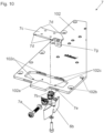
Figur 10 zeigt eine Explosionsdarstellung einer erfindungsgemäßen Einstellvorrichtung. Die Einstellvorrichtung 7 weist eine Lagerungsvorrichtung 7c auf, welche im vorliegenden Ausführungsbeispiel verschiebbar in einer Ausnehmung 102a eines Verbindungselements 102 angeordnet ist. An der Lagerungsvorrichtung 7c ist das Führungselement 6b gelagert. Es kann auch vorgesehen sein, dass die Nut 6a an der Lagerungsvorrichtung 7c gelagert ist. - Die Lagerungsvorrichtung 7c weist Vorsprünge 7d auf, welche in Vertiefungen 102c des Verbindungselements 102 eingreifen. Dadurch wird die Lagerungsvorrichtung 7c einerseits in dem Verbindungselement 102 gehalten und andererseits eine Bewegung der Lagerungsvorrichtung 7c begrenzt.
- Die Einstellvorrichtung 7 weist weiters ein Betätigungselement 7a auf. Das Betätigungselement 7a steht dabei mit Feststellelementen 7b und einer Aufnahme 7f an der Lagerungsvorrichtung 7c in Verbindung. Durch Betätigen des Betätigungselements 7a werden die Feststellelemente 7b in einem Klemmbereich 7e geklemmt. Da das Betätigungselement 7a auch mit der Lagervorrichtung 7c in Verbindung steht, ist die Lagervorrichtung somit gegenüber dem Verbindungselement 102 festgestellt. Demzufolge ist auch das Führungselement 6b gegenüber dem feststehenden Möbelteil 3 festgestellt.
- Zum Verstellen des Führungselements 6b gegenüber dem feststehenden Möbelteil 3 wird das Betätigungselement 7a betätigt, wodurch die Klemmung über die Feststellelemente 7b am Klemmbereich 7e gelöst wird. Die Lagerungsvorrichtung 7c und somit das Führungselement 6b können nun verstellt werden. Nach dem Verstellvorgang können die Lagerungsvorrichtung 7c und somit das Führungselement 6b wie bereits beschrieben festgestellt werden.
- Die Bohrungen 102b im Verbindungselement 102 dienen zur Befestigung des Verbindungselements 102 am feststehenden Möbelteil 2 bzw. an den Seitenwänden 101a.
- Die
Figuren 11a bis 11b zeigen eine erfindungsgemäße Einstellvorrichtung 7 in verschiedenen Stellungen. In derFigur 11a ist die Einstellvorrichtung in eine erste Richtung maximal verstellt, in derFigur 11b ist die Einstellvorrichtung in einer Mittelstellung angeordnet und in derFigur 11c ist die Einstellvorrichtung in eine zweite Richtung maximal verstellt. Es ist erkennbar, wie das Führungselement 6b relativ zum Verbindungselement 102 und somit zum feststehenden Möbelteil 3 verstellt wird. -
- 1
- Anordnung
- 2
- Bewegbares Möbelteil
2a Kante
2b Türprofil/Rahmen
2c Abdeckelement - 3
- Feststehendes Möbelteil
- 4
- Führungssystem
- 5
- Führungssystem
- 6
- Führungsvorrichtung
6a Nut
6b Führungselement - 7
- Einstellvorrichtung
7a Betätigungselement
7b Feststellelement
7c Lagerungsvorrichtung
7d Vorsprung
7e Klemmbereich
7f Aufnahme - 8
- Träger
8a Scharniere - 9
- Kompensationsvorrichtung
9a Schwenkhebelmechanismus
9b Seilzugvorrichtung - 100
- Möbel
- 101
- Hohlraum
101a Seitenwand - 102
- Verbindungselement
102a Ausnehmung
102b Bohrung
102c Vertiefung - 103
- Weiterer Möbelabschnitt
103a Falt-Schiebetür
103b Hohlraum
Claims (13)
- Anordnung (1) zur Führung eines bewegbaren Möbelteils (2), vorzugsweise einer Schiebetür oder FaltSchiebetür, an einem feststehenden Möbelteil (3), vorzugsweise einem Möbelkorpus, mit- zumindest einem an dem feststehenden Möbelteil (3) zu befestigenden Führungssystem (4, 5), und- einem Träger (8), an welchem das bewegbare Möbelteil (2) schwenkbar lagerbar ist und der zur mittelbaren Führung des bewegbaren Möbelteils (2) an dem feststehenden Möbelteil (3) mit dem zumindest einen Führungssystem (4, 5) beweglich verbindbar oder verbunden ist,wobei das bewegbare Möbelteil (2) eine vom zumindest einen Führungssystem (4) gesonderte Führungsvorrichtung (6) zur unmittelbaren Führung des bewegbaren Möbelteils (2) an dem feststehenden Möbelteil (3) aufweist, dadurch gekennzeichnet, dass die Anordnung (1) zumindest eine Einstellvorrichtung (7) umfasst, mittels welcher zumindest ein Teil der Führungsvorrichtung (6) relativ zu dem feststehenden Möbelteil (3), vorzugsweise in einer Richtung normal auf eine Längserstreckung des zumindest einen Führungssystems (4, 5), verstellbar ist, wobei die Einstellvorrichtung (7) ein Betätigungselement (7a) aufweist, mittels welchem die Einstellvorrichtung (7) betätigbar ist, vorzugsweise wobei das Betätigungselement (7a) in Form einer Schraube ausgeführt ist, und dass die Einstellvorrichtung (7) eine Lagervorrichtung (7c) aufweist, an welcher zumindest ein Teil der Führungsvorrichtung (6) gelagert ist, wobei die Lagervorrichtung (7c) in einer Ausnehmung (102a) eines Verbindungselements (102) bewegbar gelagert ist, vorzugsweise wobei das Verbindungselement (102) an dem feststehenden Möbelteil (3) angeordnet ist.
- Anordnung nach Anspruch 1, dadurch gekennzeichnet, dass die Führungsvorrichtung (6) zumindest eine Nut (6a) und zumindest ein bereichsweise in die zumindest eine Nut (6a) eingreifendes Führungselement (6b) umfasst.
- Anordnung nach Anspruch 2, dadurch gekennzeichnet, dass die zumindest eine Nut (6a) an dem bewegbaren Möbelteil (2) angeordnet ist, vorzugsweise wobei sich die zumindest eine Nut (6a) über die gesamte Länge einer Kante (2a) des bewegbaren Möbelteils (2) erstreckt und dass das zumindest eine Führungselement (6b) an dem feststehenden Möbelteil (3) angeordnet ist.
- Anordnung nach Anspruch 2, dadurch gekennzeichnet, dass die zumindest eine Nut (6a) an dem feststehenden Möbelteil (3) angeordnet ist und dass das zumindest eine Führungselement (6b) an dem bewegbaren Möbelteil (2) angeordnet ist, vorzugsweise wobei sich das zumindest eine Führungselement (6b) über die gesamte Länge einer Kante (2a) des bewegbaren Möbelteils (2) erstreckt.
- Anordnung nach einem der Ansprüche 1 bis 4, dadurch gekennzeichnet, dass die Anordnung eine Kompensationsvorrichtung (9) aufweist.
- Anordnung nach Anspruch 5, dadurch gekennzeichnet, dass die Kompensationsvorrichtung (9) einen Schwenkhebelmechanismus (9a) und/oder eine Seilzugvorrichtung (9b) umfasst.
- Anordnung nach einem der Ansprüche 1 bis 6, dadurch gekennzeichnet, dass die Anordnung (1) zumindest zwei, vorzugsweise vertikal voneinander beabstandete, Führungssysteme (4, 5) aufweist.
- Möbel (100) mit wenigstens einem feststehenden Möbelteil (3), wenigstens einem bewegbaren Möbelteil (2) und wenigstens einer Anordnung (1) zur Führung des bewegbaren Möbelteils (2) an dem feststehenden Möbelteil (3) nach einem der vorangehenden Ansprüche, vorzugsweise wobei das Möbel (100) einen schachtförmigen Hohlraum (101) umfasst, in welchem der wenigstens eine bewegbare Möbelteil (2) anordenbar ist.
- Möbel nach Anspruch 8, dadurch gekennzeichnet, dass das Möbel (100) einen schachtförmigen Hohlraum (101) umfasst, wobei der schachtförmige Hohlraum (101) durch zumindest zwei vorzugsweise parallele Seitenwände (101a), welche über zumindest ein Verbindungselement (102) miteinander verbunden sind, gebildet wird, wobei zumindest ein Teil der Führungsvorrichtung (6) an oder in dem zumindest einen Verbindungselement (102) angeordnet oder ausgebildet ist.
- Möbel nach Anspruch 8 oder 9, dadurch gekennzeichnet, dass das bewegbare Möbelteil (2) durch eine Schiebetür oder Falt-Schiebetür gebildet wird, vorzugsweise wobei die Schiebetür oder Faltschiebetür nur einen Türflügel umfasst.
- Möbel nach einem der Ansprüche 8 bis 10, dadurch gekennzeichnet, dass das bewegbare Möbelteil (2) einen Rahmen (2b), vorzugsweise aus einem Aluminiumprofil, und/oder eine Abdeckung (2c), vorzugsweise aus Glas, umfasst.
- Möbel nach Anspruch 11, dadurch gekennzeichnet, dass das Profil (2a) die Nut (6b) und/oder das Führungselement (6a) aufweist.
- Möbel nach Anspruch 12, dadurch gekennzeichnet, dass die Nut (6b) und/oder das Führungselement (6a) integral mit dem Profil (2a) ausgebildet ist/sind.
Priority Applications (1)
| Application Number | Priority Date | Filing Date | Title |
|---|---|---|---|
| EP24192898.5A EP4431687A3 (de) | 2020-12-17 | 2021-12-14 | Anordnung zur führung eines bewegbaren möbelteils |
Applications Claiming Priority (2)
| Application Number | Priority Date | Filing Date | Title |
|---|---|---|---|
| ATA51104/2020A AT524607B1 (de) | 2020-12-17 | 2020-12-17 | Anordnung zur Führung eines bewegbaren Möbelteils |
| PCT/AT2021/060476 WO2022126167A1 (de) | 2020-12-17 | 2021-12-14 | Anordnung zur führung eines bewegbaren möbelteils |
Related Child Applications (1)
| Application Number | Title | Priority Date | Filing Date |
|---|---|---|---|
| EP24192898.5A Division EP4431687A3 (de) | 2020-12-17 | 2021-12-14 | Anordnung zur führung eines bewegbaren möbelteils |
Publications (2)
| Publication Number | Publication Date |
|---|---|
| EP4263993A1 EP4263993A1 (de) | 2023-10-25 |
| EP4263993B1 true EP4263993B1 (de) | 2024-08-07 |
Family
ID=79024991
Family Applications (2)
| Application Number | Title | Priority Date | Filing Date |
|---|---|---|---|
| EP24192898.5A Pending EP4431687A3 (de) | 2020-12-17 | 2021-12-14 | Anordnung zur führung eines bewegbaren möbelteils |
| EP21830924.3A Active EP4263993B1 (de) | 2020-12-17 | 2021-12-14 | Anordnung zur führung eines bewegbaren möbelteils |
Family Applications Before (1)
| Application Number | Title | Priority Date | Filing Date |
|---|---|---|---|
| EP24192898.5A Pending EP4431687A3 (de) | 2020-12-17 | 2021-12-14 | Anordnung zur führung eines bewegbaren möbelteils |
Country Status (8)
| Country | Link |
|---|---|
| US (1) | US12258799B2 (de) |
| EP (2) | EP4431687A3 (de) |
| JP (1) | JP7634685B2 (de) |
| CN (1) | CN116745500B (de) |
| AT (1) | AT524607B1 (de) |
| ES (1) | ES2991964T3 (de) |
| TW (1) | TWI791350B (de) |
| WO (1) | WO2022126167A1 (de) |
Families Citing this family (2)
| Publication number | Priority date | Publication date | Assignee | Title |
|---|---|---|---|---|
| AT523872B1 (de) * | 2020-06-05 | 2023-07-15 | Blum Gmbh Julius | Führungssystem |
| AT526422B1 (de) | 2022-11-30 | 2024-03-15 | Blum Gmbh Julius | Anordnung zur Bewegung wenigstens eines Abdeckelements |
Family Cites Families (35)
| Publication number | Priority date | Publication date | Assignee | Title |
|---|---|---|---|---|
| US972412A (en) * | 1909-08-04 | 1910-10-11 | Maurice Taussig | Disappearing door. |
| US1355692A (en) * | 1917-07-12 | 1920-10-12 | Solomon Himmel | Door for display-cabinets |
| DE1963068U (de) * | 1967-01-05 | 1967-06-29 | Heinrich Niehaus | Schrankmoebel mit fluegeltuer oder klappe. |
| US3456995A (en) * | 1967-04-11 | 1969-07-22 | Gen Electric | Slide-in cabinet door |
| US4348069A (en) * | 1979-04-26 | 1982-09-07 | Lynwood Products Limited | Cabinets and doors therefor |
| FR2511236B1 (fr) * | 1981-08-14 | 1986-03-21 | Thomson Brandt | Porte escamotable et meuble muni d'une telle porte |
| JPS6169381A (ja) | 1984-09-11 | 1986-04-09 | Victor Co Of Japan Ltd | 回転制御装置 |
| JPS6169381U (de) * | 1984-10-11 | 1986-05-12 | ||
| CH670555A5 (de) * | 1986-07-02 | 1989-06-30 | Karl Haab | |
| US4821375A (en) * | 1988-01-29 | 1989-04-18 | Viking Metal Cabinet Co., Inc. | Recessing hinge mechanism |
| DD295975A5 (de) * | 1989-03-14 | 1991-11-21 | Karl Haab Und Otto Haab,Ch | Moebelstueck mit versenkbarer tuere |
| DE59003645D1 (de) * | 1989-03-14 | 1994-01-13 | Karl Haab | Möbelstück mit versenkbarer Türe. |
| US4974912A (en) * | 1989-04-05 | 1990-12-04 | Standard Precision, Inc. | Pocket door suspension system |
| DE3942584A1 (de) * | 1989-12-22 | 1991-06-27 | Weyel Kg | Einschiebe-falttuer-system fuer einen schrank |
| JPH0637480A (ja) | 1992-07-17 | 1994-02-10 | Sony Corp | シールドケースおよび受光装置 |
| JP2512647Y2 (ja) * | 1992-10-24 | 1996-10-02 | 榎本金属株式会社 | 収納ボックス |
| US5395165A (en) * | 1993-03-25 | 1995-03-07 | Hafele America Co. | Suspension system for pocket-type doors |
| DE29710854U1 (de) * | 1997-06-23 | 1997-09-04 | Heinke, Roland, 35418 Buseck | Schrank |
| DE29809193U1 (de) * | 1998-05-22 | 1998-09-03 | Heinke, Roland, 35418 Buseck | Elektrisch betätigbare Schranktüren |
| US6994410B2 (en) * | 2002-09-10 | 2006-02-07 | Knape & Vogt Manufacturing Co. | Pocket door slide |
| US20040100170A1 (en) * | 2002-11-26 | 2004-05-27 | Brown David Todd | System for a sliding door with a spacer block |
| US7090318B2 (en) * | 2002-11-26 | 2006-08-15 | Tci Supply, Inc. | System for a sliding door with a camber |
| US7068208B2 (en) * | 2003-06-16 | 2006-06-27 | Hsu-Chu Wu | Remote controlled cabinet |
| KR200359026Y1 (ko) * | 2004-05-11 | 2004-08-21 | 범일금고(주) | 대여금고 수납용 금고 |
| AT501396B1 (de) * | 2004-10-28 | 2007-10-15 | Blum Gmbh Julius | Falttürenscharnier |
| US20070159037A1 (en) * | 2006-01-10 | 2007-07-12 | Knape & Vogt Manufacturing Company | Hinge bracket for a pocket door |
| ES2397458T3 (es) * | 2009-04-28 | 2013-03-07 | Hawa Ag | Dispositivo de desplazamiento para sostener de forma pivotante elementos de separación, y artículo de mobiliario |
| IT1402815B1 (it) * | 2010-12-03 | 2013-09-27 | Borrtoluzzi Lab S R L | Dispositivo per l'applicazione di porte a scomparsa laterale, particolarmente per mobili |
| US9068386B2 (en) * | 2012-01-31 | 2015-06-30 | Sugatsune Kogyo Co., Ltd. | Stowable folding door device |
| AT516567B1 (de) * | 2014-11-26 | 2018-01-15 | Blum Gmbh Julius | Anordnung aus einer Möbeltüre und einem Hohlraum |
| DE202015008848U1 (de) * | 2015-12-22 | 2017-03-23 | Grass Gmbh | Führungseinrichtung zur Führung eines relativ zu einem Möbelkorpus bewegbaren Möbelteils |
| US9894996B1 (en) * | 2016-10-31 | 2018-02-20 | Larry Mitchell Grela | Cabinet |
| AT519908B1 (de) * | 2017-05-11 | 2020-07-15 | Blum Gmbh Julius | Möbel und Anordnung zum Einsatz für ein Möbel |
| IT201700078326A1 (it) * | 2017-07-12 | 2019-01-12 | Bortoluzzi Sistemi Spa | “mobile con ante scorrevoli e ripiegabili a scomparsa” |
| AT521139B1 (de) * | 2018-11-14 | 2019-11-15 | Blum Gmbh Julius | Führungssystem zur Führung eines bewegbar gelagerten Türflügels |
-
2020
- 2020-12-17 AT ATA51104/2020A patent/AT524607B1/de active
-
2021
- 2021-12-14 JP JP2023537037A patent/JP7634685B2/ja active Active
- 2021-12-14 ES ES21830924T patent/ES2991964T3/es active Active
- 2021-12-14 EP EP24192898.5A patent/EP4431687A3/de active Pending
- 2021-12-14 CN CN202180091517.4A patent/CN116745500B/zh active Active
- 2021-12-14 EP EP21830924.3A patent/EP4263993B1/de active Active
- 2021-12-14 WO PCT/AT2021/060476 patent/WO2022126167A1/de not_active Ceased
- 2021-12-17 TW TW110147417A patent/TWI791350B/zh active
-
2023
- 2023-06-16 US US18/210,926 patent/US12258799B2/en active Active
Also Published As
| Publication number | Publication date |
|---|---|
| WO2022126167A1 (de) | 2022-06-23 |
| JP7634685B2 (ja) | 2025-02-21 |
| AT524607B1 (de) | 2024-02-15 |
| EP4431687A3 (de) | 2024-11-27 |
| AT524607A1 (de) | 2022-07-15 |
| CN116745500B (zh) | 2026-03-31 |
| EP4431687A2 (de) | 2024-09-18 |
| EP4263993A1 (de) | 2023-10-25 |
| CN116745500A (zh) | 2023-09-12 |
| US20230332447A1 (en) | 2023-10-19 |
| US12258799B2 (en) | 2025-03-25 |
| ES2991964T3 (es) | 2024-12-05 |
| JP2023554082A (ja) | 2023-12-26 |
| TW202233097A (zh) | 2022-09-01 |
| TWI791350B (zh) | 2023-02-01 |
Similar Documents
| Publication | Publication Date | Title |
|---|---|---|
| EP1151697B1 (de) | Verstellvorrichtung zur Neigungsverstellung der Frontblende einer Schublade | |
| EP2525031A2 (de) | Türband für eine verdeckte Anordnung zwischen Türflügel und Türzarge | |
| EP2997211B1 (de) | Dreidimensionales verstellbares beschlagsystem | |
| EP4567241A2 (de) | Führungssystem zur führung eines bewegbar gelagerten türflügels | |
| EP2525032A2 (de) | Türband | |
| EP1844967A1 (de) | Schiebedachsystem | |
| EP3153646A1 (de) | Fenster- und/oder türsicherung | |
| AT523272B1 (de) | Führungssystem zur Führung eines bewegbar gelagerten Türflügels | |
| AT524607B1 (de) | Anordnung zur Führung eines bewegbaren Möbelteils | |
| EP4419771B1 (de) | Anordnung zur führung von wenigstens zwei möbeltüren | |
| EP2754813B1 (de) | Band, insbesondere für Kunststoff-Türen und -Fenster | |
| EP2913465B1 (de) | Bandanordnung für türen, fenster oder dergleichen | |
| EP4308780B1 (de) | Band fuer eine tuer oder ein fenster | |
| DE29503024U1 (de) | Flügellager | |
| AT524324B1 (de) | Lagerungsvorrichtung zur Lagerung wenigstens eines Türflügels | |
| EP2677102A1 (de) | Antrieb zum Öffnen und/oder Schließen eines beweglichen Flügels einer Tür oder eines Fensters | |
| EP3745916B1 (de) | Anordnung aus ausziehführung, schienen-synchronisierungsvorrichtung und mitnehmer | |
| EP2885475B1 (de) | Druckstange mit verspannungseinrichtung | |
| DE3718840C1 (en) | Window lifter for motor vehicles | |
| DE102018100550A1 (de) | Führungsgleiter für ein schiebetür- und/oder schiebefenstersystem, beweglicher schieberahmen mit einem führungsgleiter sowie schiebetür- und/oder schiebefenstersystem mit führungsleiter | |
| EP2454431B1 (de) | Band zur schwenkbaren verbindung eines flügels an einem rahmen | |
| EP1746235B1 (de) | Beschlaganordnung | |
| DE202015106724U1 (de) | Beschlaganordnung für einen Schiebeflügel | |
| EP3296492A1 (de) | Führungssystem für eine schiebetür sowie schiebetür mit einem führungssystem und entsprechend ausgestattetes kraftfahrzeug | |
| DE102012222210A1 (de) | Zur verdeckten Anordnung vorgesehenes Ecklager |
Legal Events
| Date | Code | Title | Description |
|---|---|---|---|
| STAA | Information on the status of an ep patent application or granted ep patent |
Free format text: STATUS: UNKNOWN |
|
| STAA | Information on the status of an ep patent application or granted ep patent |
Free format text: STATUS: THE INTERNATIONAL PUBLICATION HAS BEEN MADE |
|
| PUAI | Public reference made under article 153(3) epc to a published international application that has entered the european phase |
Free format text: ORIGINAL CODE: 0009012 |
|
| STAA | Information on the status of an ep patent application or granted ep patent |
Free format text: STATUS: REQUEST FOR EXAMINATION WAS MADE |
|
| 17P | Request for examination filed |
Effective date: 20230531 |
|
| AK | Designated contracting states |
Kind code of ref document: A1 Designated state(s): AL AT BE BG CH CY CZ DE DK EE ES FI FR GB GR HR HU IE IS IT LI LT LU LV MC MK MT NL NO PL PT RO RS SE SI SK SM TR |
|
| DAV | Request for validation of the european patent (deleted) | ||
| DAX | Request for extension of the european patent (deleted) | ||
| P01 | Opt-out of the competence of the unified patent court (upc) registered |
Effective date: 20231207 |
|
| GRAP | Despatch of communication of intention to grant a patent |
Free format text: ORIGINAL CODE: EPIDOSNIGR1 |
|
| STAA | Information on the status of an ep patent application or granted ep patent |
Free format text: STATUS: GRANT OF PATENT IS INTENDED |
|
| GRAS | Grant fee paid |
Free format text: ORIGINAL CODE: EPIDOSNIGR3 |
|
| INTG | Intention to grant announced |
Effective date: 20240531 |
|
| GRAA | (expected) grant |
Free format text: ORIGINAL CODE: 0009210 |
|
| STAA | Information on the status of an ep patent application or granted ep patent |
Free format text: STATUS: THE PATENT HAS BEEN GRANTED |
|
| AK | Designated contracting states |
Kind code of ref document: B1 Designated state(s): AL AT BE BG CH CY CZ DE DK EE ES FI FR GB GR HR HU IE IS IT LI LT LU LV MC MK MT NL NO PL PT RO RS SE SI SK SM TR |
|
| REG | Reference to a national code |
Ref country code: GB Ref legal event code: FG4D Free format text: NOT ENGLISH |
|
| REG | Reference to a national code |
Ref country code: CH Ref legal event code: EP |
|
| REG | Reference to a national code |
Ref country code: IE Ref legal event code: FG4D Free format text: LANGUAGE OF EP DOCUMENT: GERMAN |
|
| REG | Reference to a national code |
Ref country code: DE Ref legal event code: R096 Ref document number: 502021004748 Country of ref document: DE |
|
| REG | Reference to a national code |
Ref country code: LT Ref legal event code: MG9D |
|
| REG | Reference to a national code |
Ref country code: ES Ref legal event code: FG2A Ref document number: 2991964 Country of ref document: ES Kind code of ref document: T3 Effective date: 20241205 |
|
| REG | Reference to a national code |
Ref country code: NL Ref legal event code: MP Effective date: 20240807 |
|
| PG25 | Lapsed in a contracting state [announced via postgrant information from national office to epo] |
Ref country code: NO Free format text: LAPSE BECAUSE OF FAILURE TO SUBMIT A TRANSLATION OF THE DESCRIPTION OR TO PAY THE FEE WITHIN THE PRESCRIBED TIME-LIMIT Effective date: 20241107 |
|
| PG25 | Lapsed in a contracting state [announced via postgrant information from national office to epo] |
Ref country code: NL Free format text: LAPSE BECAUSE OF FAILURE TO SUBMIT A TRANSLATION OF THE DESCRIPTION OR TO PAY THE FEE WITHIN THE PRESCRIBED TIME-LIMIT Effective date: 20240807 Ref country code: FI Free format text: LAPSE BECAUSE OF FAILURE TO SUBMIT A TRANSLATION OF THE DESCRIPTION OR TO PAY THE FEE WITHIN THE PRESCRIBED TIME-LIMIT Effective date: 20240807 Ref country code: PL Free format text: LAPSE BECAUSE OF FAILURE TO SUBMIT A TRANSLATION OF THE DESCRIPTION OR TO PAY THE FEE WITHIN THE PRESCRIBED TIME-LIMIT Effective date: 20240807 Ref country code: PT Free format text: LAPSE BECAUSE OF FAILURE TO SUBMIT A TRANSLATION OF THE DESCRIPTION OR TO PAY THE FEE WITHIN THE PRESCRIBED TIME-LIMIT Effective date: 20241209 Ref country code: GR Free format text: LAPSE BECAUSE OF FAILURE TO SUBMIT A TRANSLATION OF THE DESCRIPTION OR TO PAY THE FEE WITHIN THE PRESCRIBED TIME-LIMIT Effective date: 20241108 |
|
| PG25 | Lapsed in a contracting state [announced via postgrant information from national office to epo] |
Ref country code: BG Free format text: LAPSE BECAUSE OF FAILURE TO SUBMIT A TRANSLATION OF THE DESCRIPTION OR TO PAY THE FEE WITHIN THE PRESCRIBED TIME-LIMIT Effective date: 20240807 |
|
| PG25 | Lapsed in a contracting state [announced via postgrant information from national office to epo] |
Ref country code: LV Free format text: LAPSE BECAUSE OF FAILURE TO SUBMIT A TRANSLATION OF THE DESCRIPTION OR TO PAY THE FEE WITHIN THE PRESCRIBED TIME-LIMIT Effective date: 20240807 |
|
| PG25 | Lapsed in a contracting state [announced via postgrant information from national office to epo] |
Ref country code: IS Free format text: LAPSE BECAUSE OF FAILURE TO SUBMIT A TRANSLATION OF THE DESCRIPTION OR TO PAY THE FEE WITHIN THE PRESCRIBED TIME-LIMIT Effective date: 20241207 |
|
| PG25 | Lapsed in a contracting state [announced via postgrant information from national office to epo] |
Ref country code: HR Free format text: LAPSE BECAUSE OF FAILURE TO SUBMIT A TRANSLATION OF THE DESCRIPTION OR TO PAY THE FEE WITHIN THE PRESCRIBED TIME-LIMIT Effective date: 20240807 |
|
| PG25 | Lapsed in a contracting state [announced via postgrant information from national office to epo] |
Ref country code: RS Free format text: LAPSE BECAUSE OF FAILURE TO SUBMIT A TRANSLATION OF THE DESCRIPTION OR TO PAY THE FEE WITHIN THE PRESCRIBED TIME-LIMIT Effective date: 20241107 |
|
| PG25 | Lapsed in a contracting state [announced via postgrant information from national office to epo] |
Ref country code: RS Free format text: LAPSE BECAUSE OF FAILURE TO SUBMIT A TRANSLATION OF THE DESCRIPTION OR TO PAY THE FEE WITHIN THE PRESCRIBED TIME-LIMIT Effective date: 20241107 Ref country code: PT Free format text: LAPSE BECAUSE OF FAILURE TO SUBMIT A TRANSLATION OF THE DESCRIPTION OR TO PAY THE FEE WITHIN THE PRESCRIBED TIME-LIMIT Effective date: 20241209 Ref country code: PL Free format text: LAPSE BECAUSE OF FAILURE TO SUBMIT A TRANSLATION OF THE DESCRIPTION OR TO PAY THE FEE WITHIN THE PRESCRIBED TIME-LIMIT Effective date: 20240807 Ref country code: NO Free format text: LAPSE BECAUSE OF FAILURE TO SUBMIT A TRANSLATION OF THE DESCRIPTION OR TO PAY THE FEE WITHIN THE PRESCRIBED TIME-LIMIT Effective date: 20241107 Ref country code: NL Free format text: LAPSE BECAUSE OF FAILURE TO SUBMIT A TRANSLATION OF THE DESCRIPTION OR TO PAY THE FEE WITHIN THE PRESCRIBED TIME-LIMIT Effective date: 20240807 Ref country code: LV Free format text: LAPSE BECAUSE OF FAILURE TO SUBMIT A TRANSLATION OF THE DESCRIPTION OR TO PAY THE FEE WITHIN THE PRESCRIBED TIME-LIMIT Effective date: 20240807 Ref country code: IS Free format text: LAPSE BECAUSE OF FAILURE TO SUBMIT A TRANSLATION OF THE DESCRIPTION OR TO PAY THE FEE WITHIN THE PRESCRIBED TIME-LIMIT Effective date: 20241207 Ref country code: HR Free format text: LAPSE BECAUSE OF FAILURE TO SUBMIT A TRANSLATION OF THE DESCRIPTION OR TO PAY THE FEE WITHIN THE PRESCRIBED TIME-LIMIT Effective date: 20240807 Ref country code: GR Free format text: LAPSE BECAUSE OF FAILURE TO SUBMIT A TRANSLATION OF THE DESCRIPTION OR TO PAY THE FEE WITHIN THE PRESCRIBED TIME-LIMIT Effective date: 20241108 Ref country code: FI Free format text: LAPSE BECAUSE OF FAILURE TO SUBMIT A TRANSLATION OF THE DESCRIPTION OR TO PAY THE FEE WITHIN THE PRESCRIBED TIME-LIMIT Effective date: 20240807 Ref country code: BG Free format text: LAPSE BECAUSE OF FAILURE TO SUBMIT A TRANSLATION OF THE DESCRIPTION OR TO PAY THE FEE WITHIN THE PRESCRIBED TIME-LIMIT Effective date: 20240807 |
|
| PG25 | Lapsed in a contracting state [announced via postgrant information from national office to epo] |
Ref country code: DK Free format text: LAPSE BECAUSE OF FAILURE TO SUBMIT A TRANSLATION OF THE DESCRIPTION OR TO PAY THE FEE WITHIN THE PRESCRIBED TIME-LIMIT Effective date: 20240807 Ref country code: SM Free format text: LAPSE BECAUSE OF FAILURE TO SUBMIT A TRANSLATION OF THE DESCRIPTION OR TO PAY THE FEE WITHIN THE PRESCRIBED TIME-LIMIT Effective date: 20240807 |
|
| PG25 | Lapsed in a contracting state [announced via postgrant information from national office to epo] |
Ref country code: EE Free format text: LAPSE BECAUSE OF FAILURE TO SUBMIT A TRANSLATION OF THE DESCRIPTION OR TO PAY THE FEE WITHIN THE PRESCRIBED TIME-LIMIT Effective date: 20240807 |
|
| PG25 | Lapsed in a contracting state [announced via postgrant information from national office to epo] |
Ref country code: CZ Free format text: LAPSE BECAUSE OF FAILURE TO SUBMIT A TRANSLATION OF THE DESCRIPTION OR TO PAY THE FEE WITHIN THE PRESCRIBED TIME-LIMIT Effective date: 20240807 |
|
| PG25 | Lapsed in a contracting state [announced via postgrant information from national office to epo] |
Ref country code: SK Free format text: LAPSE BECAUSE OF FAILURE TO SUBMIT A TRANSLATION OF THE DESCRIPTION OR TO PAY THE FEE WITHIN THE PRESCRIBED TIME-LIMIT Effective date: 20240807 |
|
| REG | Reference to a national code |
Ref country code: DE Ref legal event code: R097 Ref document number: 502021004748 Country of ref document: DE |
|
| PLBE | No opposition filed within time limit |
Free format text: ORIGINAL CODE: 0009261 |
|
| STAA | Information on the status of an ep patent application or granted ep patent |
Free format text: STATUS: NO OPPOSITION FILED WITHIN TIME LIMIT |
|
| PG25 | Lapsed in a contracting state [announced via postgrant information from national office to epo] |
Ref country code: MC Free format text: LAPSE BECAUSE OF FAILURE TO SUBMIT A TRANSLATION OF THE DESCRIPTION OR TO PAY THE FEE WITHIN THE PRESCRIBED TIME-LIMIT Effective date: 20240807 |
|
| 26N | No opposition filed |
Effective date: 20250508 |
|
| PG25 | Lapsed in a contracting state [announced via postgrant information from national office to epo] |
Ref country code: LU Free format text: LAPSE BECAUSE OF NON-PAYMENT OF DUE FEES Effective date: 20241214 |
|
| PG25 | Lapsed in a contracting state [announced via postgrant information from national office to epo] |
Ref country code: SE Free format text: LAPSE BECAUSE OF FAILURE TO SUBMIT A TRANSLATION OF THE DESCRIPTION OR TO PAY THE FEE WITHIN THE PRESCRIBED TIME-LIMIT Effective date: 20240807 |
|
| REG | Reference to a national code |
Ref country code: BE Ref legal event code: MM Effective date: 20241231 |
|
| PG25 | Lapsed in a contracting state [announced via postgrant information from national office to epo] |
Ref country code: BE Free format text: LAPSE BECAUSE OF NON-PAYMENT OF DUE FEES Effective date: 20241231 |
|
| PG25 | Lapsed in a contracting state [announced via postgrant information from national office to epo] |
Ref country code: FR Free format text: LAPSE BECAUSE OF NON-PAYMENT OF DUE FEES Effective date: 20241231 |
|
| PG25 | Lapsed in a contracting state [announced via postgrant information from national office to epo] |
Ref country code: IE Free format text: LAPSE BECAUSE OF NON-PAYMENT OF DUE FEES Effective date: 20241214 |
|
| PG25 | Lapsed in a contracting state [announced via postgrant information from national office to epo] |
Ref country code: RO Free format text: LAPSE BECAUSE OF FAILURE TO SUBMIT A TRANSLATION OF THE DESCRIPTION OR TO PAY THE FEE WITHIN THE PRESCRIBED TIME-LIMIT Effective date: 20240807 |
|
| REG | Reference to a national code |
Ref country code: CH Ref legal event code: U11 Free format text: ST27 STATUS EVENT CODE: U-0-0-U10-U11 (AS PROVIDED BY THE NATIONAL OFFICE) Effective date: 20260101 |
|
| PGFP | Annual fee paid to national office [announced via postgrant information from national office to epo] |
Ref country code: AT Payment date: 20260113 Year of fee payment: 5 |
|
| PG25 | Lapsed in a contracting state [announced via postgrant information from national office to epo] |
Ref country code: IT Free format text: LAPSE BECAUSE OF NON-PAYMENT OF DUE FEES Effective date: 20241214 |
|
| PGFP | Annual fee paid to national office [announced via postgrant information from national office to epo] |
Ref country code: TR Payment date: 20251126 Year of fee payment: 5 |
|
| PGFP | Annual fee paid to national office [announced via postgrant information from national office to epo] |
Ref country code: ES Payment date: 20260122 Year of fee payment: 5 |
|
| PGFP | Annual fee paid to national office [announced via postgrant information from national office to epo] |
Ref country code: DE Payment date: 20251229 Year of fee payment: 5 |
|
| PG25 | Lapsed in a contracting state [announced via postgrant information from national office to epo] |
Ref country code: IT Free format text: LAPSE BECAUSE OF NON-PAYMENT OF DUE FEES Effective date: 20241214 |
|
| PGFP | Annual fee paid to national office [announced via postgrant information from national office to epo] |
Ref country code: IT Payment date: 20251218 Year of fee payment: 5 |
|
| PGRI | Patent reinstated in contracting state [announced from national office to epo] |
Ref country code: IT Effective date: 20241231 |
|
| PGFP | Annual fee paid to national office [announced via postgrant information from national office to epo] |
Ref country code: CH Payment date: 20260101 Year of fee payment: 5 |
|
| PG25 | Lapsed in a contracting state [announced via postgrant information from national office to epo] |
Ref country code: CY Free format text: LAPSE BECAUSE OF FAILURE TO SUBMIT A TRANSLATION OF THE DESCRIPTION OR TO PAY THE FEE WITHIN THE PRESCRIBED TIME-LIMIT Effective date: 20240807 |