EP4265085B1 - Landwirtschaftliches arbeitsgerät - Google Patents
Landwirtschaftliches arbeitsgerät Download PDFInfo
- Publication number
- EP4265085B1 EP4265085B1 EP22169386.4A EP22169386A EP4265085B1 EP 4265085 B1 EP4265085 B1 EP 4265085B1 EP 22169386 A EP22169386 A EP 22169386A EP 4265085 B1 EP4265085 B1 EP 4265085B1
- Authority
- EP
- European Patent Office
- Prior art keywords
- rotor
- agricultural implement
- implement according
- chassis
- hydraulic line
- Prior art date
- Legal status (The legal status is an assumption and is not a legal conclusion. Google has not performed a legal analysis and makes no representation as to the accuracy of the status listed.)
- Active
Links
Images


Classifications
-
- A—HUMAN NECESSITIES
- A01—AGRICULTURE; FORESTRY; ANIMAL HUSBANDRY; HUNTING; TRAPPING; FISHING
- A01D—HARVESTING; MOWING
- A01D78/00—Haymakers with tines moving with respect to the machine
- A01D78/08—Haymakers with tines moving with respect to the machine with tine-carrying rotary heads or wheels
- A01D78/10—Haymakers with tines moving with respect to the machine with tine-carrying rotary heads or wheels the tines rotating about a substantially vertical axis
- A01D78/1007—Arrangements to facilitate transportation specially adapted therefor
-
- A—HUMAN NECESSITIES
- A01—AGRICULTURE; FORESTRY; ANIMAL HUSBANDRY; HUNTING; TRAPPING; FISHING
- A01B—SOIL WORKING IN AGRICULTURE OR FORESTRY; PARTS, DETAILS, OR ACCESSORIES OF AGRICULTURAL MACHINES OR IMPLEMENTS, IN GENERAL
- A01B33/00—Tilling implements with rotary driven tools, e.g. in combination with fertiliser distributors or seeders, with grubbing chains, with sloping axles, with driven discs
- A01B33/06—Tilling implements with rotary driven tools, e.g. in combination with fertiliser distributors or seeders, with grubbing chains, with sloping axles, with driven discs with tools on vertical or steeply-inclined shaft
-
- A—HUMAN NECESSITIES
- A01—AGRICULTURE; FORESTRY; ANIMAL HUSBANDRY; HUNTING; TRAPPING; FISHING
- A01B—SOIL WORKING IN AGRICULTURE OR FORESTRY; PARTS, DETAILS, OR ACCESSORIES OF AGRICULTURAL MACHINES OR IMPLEMENTS, IN GENERAL
- A01B33/00—Tilling implements with rotary driven tools, e.g. in combination with fertiliser distributors or seeders, with grubbing chains, with sloping axles, with driven discs
- A01B33/08—Tools; Details, e.g. adaptations of transmissions or gearings
- A01B33/10—Structural or functional features of the tools ; Theoretical aspects of the cutting action
- A01B33/106—Structural or functional features of the tools ; Theoretical aspects of the cutting action the rotating shaft being oriented vertically or steeply inclined
-
- A—HUMAN NECESSITIES
- A01—AGRICULTURE; FORESTRY; ANIMAL HUSBANDRY; HUNTING; TRAPPING; FISHING
- A01B—SOIL WORKING IN AGRICULTURE OR FORESTRY; PARTS, DETAILS, OR ACCESSORIES OF AGRICULTURAL MACHINES OR IMPLEMENTS, IN GENERAL
- A01B63/00—Lifting or adjusting devices or arrangements for agricultural machines or implements
- A01B63/002—Devices for adjusting or regulating the position of tools or wheels
- A01B63/008—Vertical adjustment of tools
-
- A—HUMAN NECESSITIES
- A01—AGRICULTURE; FORESTRY; ANIMAL HUSBANDRY; HUNTING; TRAPPING; FISHING
- A01B—SOIL WORKING IN AGRICULTURE OR FORESTRY; PARTS, DETAILS, OR ACCESSORIES OF AGRICULTURAL MACHINES OR IMPLEMENTS, IN GENERAL
- A01B63/00—Lifting or adjusting devices or arrangements for agricultural machines or implements
- A01B63/14—Lifting or adjusting devices or arrangements for agricultural machines or implements for implements drawn by animals or tractors
- A01B63/16—Lifting or adjusting devices or arrangements for agricultural machines or implements for implements drawn by animals or tractors with wheels adjustable relatively to the frame
-
- A—HUMAN NECESSITIES
- A01—AGRICULTURE; FORESTRY; ANIMAL HUSBANDRY; HUNTING; TRAPPING; FISHING
- A01D—HARVESTING; MOWING
- A01D78/00—Haymakers with tines moving with respect to the machine
- A01D78/08—Haymakers with tines moving with respect to the machine with tine-carrying rotary heads or wheels
- A01D78/10—Haymakers with tines moving with respect to the machine with tine-carrying rotary heads or wheels the tines rotating about a substantially vertical axis
- A01D78/105—Ground support for rotors
-
- A—HUMAN NECESSITIES
- A01—AGRICULTURE; FORESTRY; ANIMAL HUSBANDRY; HUNTING; TRAPPING; FISHING
- A01D—HARVESTING; MOWING
- A01D78/00—Haymakers with tines moving with respect to the machine
- A01D78/08—Haymakers with tines moving with respect to the machine with tine-carrying rotary heads or wheels
- A01D78/10—Haymakers with tines moving with respect to the machine with tine-carrying rotary heads or wheels the tines rotating about a substantially vertical axis
- A01D78/1071—Having only one rotor
Definitions
- the invention relates to an agricultural implement according to the preamble of claim 1.
- a generic agricultural implement is known, for example, in the form of a towed rotary swather.
- This can comprise a front and a rear rotor, each with working tools designed as spring tines, whereby the rotors can be mounted on separate chassis.
- the chassis of the rear rotor must then be lifted separately from a working position with lowered working tools to a transport position with raised working tools.
- Suitable four-wheel chassis for this comprise front and rear running wheels, whereby the rear ones make contact with the ground in the transport position and the front ones are then lifted.
- Lifting is preferably carried out using a swing arm construction that is adjusted by a hydraulic cylinder. Since the hydraulic cylinder is located below the rotor assigned to the chassis, the hydraulic cylinder is usually operated via a hydraulic line that runs from top to bottom through the axis of rotation of the rotor.
- the working height of the rotor (height in the working position in relation to the surface being driven on) is set on the type of implement or rotary rake by adjusting the positions of the running wheels on the chassis. To do this, the front and rear running wheels of the chassis must be adjusted separately, and this is only possible when the chassis is unloaded, i.e. in the transport position. In addition, the height adjustment must be carried out manually using tools underneath the rotor.
- DE10 2014 014131 discloses a haymaking machine with at least one rake rotor which can be driven in rotation about an upright rake rotor axis and is supported on the ground by a sensor chassis, wherein a height adjustment device is provided for adjusting the height of the sensor chassis along the rake rotor axis.
- the agricultural implement comprises a chassis, a rotor mounted thereon and rotatable about an upright axis with working tools and a hydraulic lifting device for lifting the chassis between a working position and a transport position, in which the rotor is raised further in relation to the ground being driven on than in the working position.
- the lifting device is arranged below the rotor and is connected to a hydraulic line that runs from top to bottom through the rotor.
- the agricultural implement comprises an adjustment mechanism for adjusting the height of the rotor for the working position, or in other words for adjusting the working height of the rotor.
- the adjustment mechanism comprises a tubular adjusting element that surrounds the hydraulic line or forms it in sections, with at least one axial adjusting thread that supports the rotor and the chassis in a mutually supporting manner, and an actuating device arranged above the rotor for axial and, in particular, tool-free rotation of the adjusting element.
- the adjusting element can be rotated by the actuating device about the axis of rotation of the rotor, for example by means of a handwheel, a crank or a drive motor, in order to adjust the height of the rotor in the working position with respect to the chassis that supports it by means of the adjusting thread.
- the working height of the rotor can therefore be ergonomically adjusted on its top using the operating device.
- the height adjustment of the rotor is relative to the chassis as a whole, so that the front and rear wheels of a four-wheel chassis no longer have to be adjusted separately. This makes it possible to adjust the height of the rotor without changing its inclination at the same time. Repeated corrections are therefore generally no longer necessary when adjusting the height.
- the hydraulic line is preferably designed to be rigid for axially supporting the rotor and the chassis, or to provide mutual support. This enables a compact design.
- the tubular adjusting element enables, for example, a height adjustment of 30 to 150 mm.
- Types M22 x 1.5 and/or M16 x 1.5 are suitable as adjusting threads.
- a combination of different thread pitches and/or a combination of right-hand and left-hand threads is also possible.
- the tubular adjusting element is a threaded bushing surrounding the hydraulic line with an internal thread (first adjusting thread) that interacts with an external thread formed on the hydraulic line.
- first adjusting thread an internal thread
- an axial stroke of the hydraulic line can be achieved depending on the thread pitch without the hydraulic line rotating with the threaded bushing. This enables a structurally simple connection of the hydraulic line above and below the rotor and adjustability under load.
- the threaded bushing further comprises an opposing external thread (second adjusting thread) which cooperates with an internal thread which is arranged in a rotationally fixed manner on a rotor axis or a housing which is designed to support the rotor.
- second adjusting thread an opposing external thread
- the internal thread and the external thread of the threaded bushing are designed to run in opposite directions to one another.
- the partial strokes caused by the thread pitches of the internal and external threads of the threaded bushing when they rotate add up to a total stroke of the height adjustment, which enables a compact design and quick height adjustment.
- the threaded bushing is mounted on its outside at a fixed height on a rotor axis or a housing, which is also designed to support the rotor.
- the actuating device can thus be arranged relatively easily in the area of the rotor, for example on the so-called rotor head. This also favors a motor drive of the actuating device.
- the hydraulic line is attached to the actuator in a non-rotating manner. This facilitates the hydraulic connection on both sides to permanently installed pressure hoses or the like.
- the actuating element is designed in the form of a hollow spindle (rigid tubular spindle with external thread) as part of the hydraulic line, which then comprises hydraulic rotary unions at its ends.
- the rigid hydraulic line rotates the height adjustment of the rotor then inevitably follows.
- hydraulic rotary unions enable a non-rotating connection of the hydraulic line on the top and bottom of the rotor to pressure hose lines or similar lines, for example to the hydraulic lifting device.
- the supporting actuating element and hydraulic line can thus be provided relatively easily and in a space-saving manner in the form of the hollow spindle.
- the actuating device comprises a bevel gear or worm gear connected to the actuating element. This enables a comparatively simple manual height adjustment by means of a hand crank or a motor drive.
- the actuating device preferably comprises an electric drive motor. This enables flexible and quick height adjustment of the rotor, for example in different working situations, and makes manual adjustment of the working height unnecessary. In addition, previously saved working heights can be set using an associated electronic control unit.
- the actuating device comprises a handwheel fixed coaxially to the actuating element. This is comparatively compact and can advantageously be permanently attached to the rotor head.
- the adjustment mechanism for height adjustment/setting the working height is designed to be under the rotor's own weight in the working position. It is then no longer necessary to relieve the chassis or lift it out to adjust the height of the rotor. Set working heights can therefore be checked quickly and easily.
- the height setting can be displayed above the rotor using a scale that can be read from a tractor, for example, and thus by its driver from a distance.
- the chassis preferably comprises front and rear wheels, i.e. it is designed as a four-wheel chassis, with the rear wheels in contact with the ground in the transport position and the front wheels being raised. This makes it possible to provide an effective lifting device that works particularly advantageously with the adjustment mechanism described.
- the chassis comprises a swing arm with wheels mounted thereon, wherein the lifting device comprises at least one hydraulic cylinder for pivoting the swing arm.
- the lifting device comprises at least one hydraulic cylinder for pivoting the swing arm.
- This also serves as a lifting device that can be combined particularly well with the adjustment mechanism according to the invention.
- the agricultural implement is a towed rotary swather.
- This then preferably comprises a front and a rear rotor, wherein the described Chassis and the adjustment mechanism are assigned separately to the rear rotor. Since the adjustment mechanism on the rear rotor is relatively far away from an associated tractor, it works particularly advantageously together with the lifting device.
- the agricultural implement according to at least one of the described embodiments could, for example, also be a towed rotary tedder.
- the agricultural implement 1 which in the example is a towed rotary swather, comprises a chassis 2, a rotor 3 mounted thereon and rotatable about an upright axis 3a with working tools 3b, which in the example are spring tines, and a hydraulic lifting device 4 for lifting the chassis 2 between a Figure 1A exemplary working position 5 and one in the Figure 1B transport position 6 shown as an example.
- the rotor 3 is in particular the rear rotor of a two-rotor rake.
- a drive 3c for the rotor 3 can be seen, which is arranged in a gear head above the rotor 3 in a manner known in principle.
- the direction of travel 1a (behind a tractor not shown) is indicated by an arrow in the Figure 1B indicated schematically.
- the lifting device 4 is arranged below the rotor 3 and is connected to a tubular hydraulic line 7 which runs from top to bottom through the rotor 3, for example by means of a pressure hose line which is known in principle and therefore not described further.
- the working device 1 further comprises an adjustment mechanism 8 for adjusting the height of the rotor 3 in the working position 5 with respect to the chassis 2.
- the adjustment mechanism 8 comprises a tubular adjusting element 8a surrounding the hydraulic line 7 or forming it in sections and an actuating device 8b arranged above the rotor 3 for rotating the adjusting element 8a about the axis 3a. This enables a height adjustment in the working position 5 Set the effective working height 9 of the rotor 3 by raising or lowering it linearly with respect to the completely lowered chassis 2.
- the tubular adjusting element 8a can be designed as a threaded bushing 10 surrounding the hydraulic line 7 with an internal thread (first adjusting thread) 10a, which interacts with an external thread 7a formed on the rigid hydraulic line 7.
- a thread of type M16 x 1.5_L is suitable for this, for example.
- the threaded bushing 10 can comprise an external thread (second adjusting thread) 10b, which interacts with an internal thread 11a formed on a rotor axis 11, a gear housing or the like fixed structure for supporting the rotor 3.
- a thread of the type M22 x 1.5_R is suitable for this purpose, for example.
- chassis 2 and the rotor 3 support each other via the hydraulic line 7, the threaded bushing 10 and the non-rotating rotor axis 11 or similar supporting structure.
- the internal thread 10a and the external thread 10b of the threaded bushing 10 are designed in opposite directions (for example a right-hand thread on the outside and a left-hand thread on the inside, or vice versa). Turning the threaded bushing 10 then simultaneously causes a first partial stroke 12a between the hydraulic line 7 and the threaded bushing 10 and a second partial stroke 12b between the threaded bushing 10 and the rotor axis 11.
- the partial strokes 12a, 12b thus add up to an adjustment stroke 12 between the rotor axis 11 with the rotor 3 vertically attached to it on the one hand and the frame 2 with the hydraulic line 7 vertically attached to it on the other.
- the hydraulic line 7 then does not rotate as a whole during the height adjustment, so that pressure hoses or similar lines laid on the working device 1 can be connected directly in an uncomplicated manner.
- the adjustment stroke 12 is, for example, 30 to 150 mm. This can be achieved by combining the partial strokes 12a, 12b in a compact design.
- the actuating device 8b can comprise a handwheel 13 which is attached coaxially to the axis 3a on the tubular actuating element 8a / the threaded bushing 10.
- handwheel 13 is missing.
- FIGS. 3A and 3B show a second preferred embodiment of the adjustment mechanism 8, which differs essentially from the previously described embodiment in that the threaded bushing 10 and the rotor axis 11 do not support each other by threads, but by means of a vertically (axially) fixed bearing 14.
- the threaded bushing 10 then does not comprise an external thread (second adjusting thread) 10b.
- the working height 9 of the rotor 3 with respect to the hydraulic line 7 and the chassis 2 is then adjusted accordingly only by means of the internal thread (first adjusting thread) 10a of the threaded bushing 10 and the external thread 7a of the rigid hydraulic line 7, which, however, does not rotate in the process.
- the adjustment stroke 12 in this embodiment is identical to the previously described first partial stroke 12a.
- the actuating device 8b can comprise a bevel gear 15 and/or a drive motor 16 in order to actuate the adjustment mechanism 8 by motor and, if necessary, automatically.
- the drive motor 16 could also be connected to the tubular actuating element 8a via another gear.
- the bevel gear 15 could also be driven manually by means of a hand crank or the like.
- the drive motor 16 is preferably assigned an electronic control unit 16a, with which different working heights 9 can be approached in a targeted and reproducible manner, for example as a result of programming. Operation would then also be possible, for example, via radio from a tractor. It goes without saying that the control unit 16a does not have to be arranged in the vicinity of the drive motor 16.
- An advantage of the second embodiment of the adjustment mechanism 8 is that the actuating device 8b, for example the bevel gear 15 and the drive motor 16, can be arranged at a fixed height with respect to the rotor 3 and the rotor axis 11 or the like supporting structure for the rotor 3 due to the lack of a second partial stroke 12b. This can be particularly advantageous when the adjustment mechanism 8 is motor-driven.
- FIGS. 4A to 4C show a third preferred embodiment of the adjustment mechanism 8, which differs from the previously described embodiments essentially in that the tubular adjusting element 8a is designed as a hollow spindle 17, which forms a supporting section of the hydraulic line 7 and rotates about the axis 3a during the described height adjustment of the rotor 3.
- the rigid hollow spindle 17 comprises an external thread (third adjusting thread as an alternative to the first and possibly second adjusting thread) 17a, which interacts in the manner described above with an internal thread 11a formed on the non-rotating rotor axis 11 or the like support structure during the height adjustment. Accordingly, the adjustment stroke 12 in this embodiment is identical to the second partial stroke 12b described above.
- the hydraulic line 7 comprises rotary unions 18 at the upper and lower ends of the rigid hollow spindle 17, which each provide a pressure-tight connection to pressure hoses or similar lines that do not rotate during the height adjustment.
- the hollow spindle 17 is supported downwards by an axial bearing 20 on the carrier 2a.
- the actuating device 8b may, for example, comprise a worm gear 19 which is Figures 4A to 4C is only indicated schematically and by way of example. This could be driven by means of a hand crank (not shown) or by a motor.
- the described embodiments of the actuating device 8b can be combined with all described embodiments of the tubular adjusting element 8a.
- the decisive factor here is that the actuating device 8b is arranged above the rotor 3 and is therefore easily and ergonomically accessible for an operator or allows a simple motor drive.
- the tubular adjusting element 8a in all embodiments causes a linear height adjustment of the rotor 3 with respect to the chassis 2 without changing the rotor inclination, so that step-by-step checking and correction of the height adjustment made is unnecessary.
- the adjusting threads 10a and possibly 10b on the one hand or 17a on the other hand which are present according to the embodiment according to the invention, enable the working height 9 to be adjusted when the chassis 2 is lowered into the working position 5 and thus under the dead load caused by the rotor 3.
- the chassis 2 therefore no longer has to be lifted out and relieved in order to adjust the working height 9.
- settings of the working height 9 made using the adjustment mechanism 8 can be checked immediately in the working position 5 and corrected if necessary.
- the agricultural implement 1 is, for example, a rotary swather, with the rotor 3 being assigned a separate chassis 2, which comprises a carrier 2a known in principle for mounting the rotor 3 on the chassis 2 and a swing arm 2b which can be pivoted in this respect with rear wheels 2c.
- Front wheels 2d assigned to these in the sense of a four-wheel chassis are, however, preferably mounted at a fixed height with respect to the carrier 2a.
- the chassis 2 comprises the lifting device 4 with at least one hydraulic cylinder 4a, which is known in principle and is coupled to the swing arm 2b in order to position it with respect to the carrier 2a.
- the lifting device 4 with at least one hydraulic cylinder 4a, which is known in principle and is coupled to the swing arm 2b in order to position it with respect to the carrier 2a.
- the swing arm 2b is spread, the carrier 2a with the front wheels 2d and the rotor 3 is lifted into the transport position 6, with the rear wheels 2c making permanent contact with the ground in a known manner.
- Such lifting devices 4 are tried and tested and can be easily combined with the adjustment mechanism 8 according to the invention.
- Such a combination of adjustment mechanism 8 and lifting device 4 on a possibly rear rotor 3 and chassis 2 of a towed rotary swather with at least one rotor 3 is particularly advantageous.
- a rotor 3 that is comparatively far away from an associated tractor (not shown) can, on the one hand, be placed in the transport position 6 with the lifting device 4 in a proven manner and, on the other hand, its working height 9 in the lowered working position 5 can be adjusted easily and ergonomically.
- the described adjustment mechanism 8 could also be used on other agricultural implements with implements rotating around essentially upright axes and a coaxial hydraulic line, for example on a rotary hay rake. This can be used, for example, in the EP 0 627 878 A1 , EN 29 30 152 A1 and/or DE 196 19 172 A1 have the characteristics described.
Landscapes
- Life Sciences & Earth Sciences (AREA)
- Environmental Sciences (AREA)
- Engineering & Computer Science (AREA)
- Mechanical Engineering (AREA)
- Soil Sciences (AREA)
- Zoology (AREA)
- Agricultural Machines (AREA)
Description
- Die Erfindung betrifft ein landwirtschaftliches Arbeitsgerät gemäß dem Oberbegriff des Anspruchs 1.
- Ein gattungsgemäßes landwirtschaftliches Arbeitsgerät ist beispielsweise in Form eines gezogenen Kreiselschwaders bekannt. Dieser kann einen vorderen und einen hinteren Rotor jeweils mit als Federzinken ausgebildeten Arbeitswerkzeugen umfassen, wobei die Rotoren auf separaten Fahrwerken gelagert sein können. Beispielsweise muss das Fahrwerk des hinteren Rotors dann von einer Arbeitsstellung mit abgesenkten Arbeitswerkzeugen in eine Transportstellung mit angehobenen Arbeitswerkzeugen separat ausgehoben werden. Dafür geeignete Vierradfahrwerke umfassen vordere und hintere Laufräder, wobei die hinteren den Bodenkontakt in der Transportstellung herstellen und die vorderen dann ausgehoben sind. Das Ausheben erfolgt vorzugsweise mit Hilfe einer Schwingenkonstruktion, die von einem Hydraulikzylinder verstellt wird. Da sich der Hydraulikzylinder unterhalb des dem Fahrwerk zugeordneten Rotors befindet, wird der Hydraulikzylinder in der Regel über eine durch die Drehachse des Rotors von oben nach unten geführte Hydraulikleitung betrieben.
- Da die Höhenlage des Rotors bezüglich des Fahrwerks bei derartigen Arbeitsgeräten festgelegt ist, stellt man die Arbeitshöhe des Rotors (Höhenlage in der Arbeitsstellung bezüglich des befahrenen Untergrunds) beim gattungsgemäßen Arbeitsgerät bzw. Kreiselschwader ein, indem man die Positionen der Laufräder am Fahrwerk verstellt. Hierfür müssen zum einen die vorderen und hinteren Laufräder des Fahrwerks separat verstellt werden, und zum anderen ist dies nur bei entlastetem Fahrwerk möglich, also in der Transportstellung. Zudem muss die Höheneinstellung mit Werkzeugen unterhalb des Rotors manuell vorgenommen werden.
- Das Einstellen der Arbeitshöhe des Rotors ist somit in der Praxis bisher sehr kompliziert, so dass dies oftmals nur bei der Erstinbetriebnahme erfolgt. Dies liegt unter anderem auch daran, dass sich die Höhenverstellung an den vorderen und hinteren Laufrädern gegenseitig beeinflusst, da dabei auch die Neigung des Arbeitsgeräts verändert wird. In der Praxis sind daher wiederholte Einstellschritte nötig, also ein schrittweises Verstellen der vorderen und hinteren Laufräder in der Transportstellung, ein Absenken in die Arbeitsstellung und Überprüfen der erzielten Einstellung gegebenenfalls mit wiederholter Korrektur der Einstellung. Dies ist aufgrund der Anordnung der Einstellmechanik unterhalb des Rotors unergonomisch und gefährlich.
DE10 2014 014131 offenbart eine Heuwerbungsmaschine mit zumindest einem Rechkreisel, der um eine aufrechte Rechkreiselachse umlaufend antreibbar und von einem Tastfahrwerk am Boden abgestützt ist, wobei eine Höhenverstellvorrichtung zum Höhenverstellen des Tastfahrwerks entlang der Rechkreiselachse vorgesehen ist. - Es besteht Bedarf für demgegenüber verbesserte landwirtschaftliche Arbeitsgeräte, insbesondere Kreiselschwader, um die Höhenverstellung des Rotors für die Arbeitsstellung einfacher, sicherer und ergonomischer zu gestalten.
- Die gestellte Aufgabe wird mit einem landwirtschaftlichen Arbeitsgerät nach Anspruch 1 gelöst. Bevorzugte Ausführungsformen sind in den Unteransprüchen angegeben.
- Demnach umfasst das landwirtschaftliche Arbeitsgerät ein Fahrwerk, einen darauf gelagerten und um eine aufrechte Achse drehbaren Rotor mit Arbeitswerkzeugen und eine hydraulische Aushebevorrichtung zum Ausheben des Fahrwerks zwischen einer Arbeitsstellung und einer Transportstellung, bei welcher der Rotor bezüglich des befahrenen Untergrunds weiter ausgehoben ist als in der Arbeitsstellung. Die Aushebevorrichtung ist unterhalb des Rotors angeordnet und an eine von oben nach unten durch den Rotor geführte Hydraulikleitung angeschlossen. Zudem umfasst das landwirtschaftliche Arbeitsgerät eine Einstellmechanik zur Höhenverstellung des Rotors für die Arbeitsstellung, oder anders gesagt zur Verstellung der Arbeitshöhe des Rotors.
- Erfindungsgemäß umfasst die Einstellmechanik ein die Hydraulikleitung umgebendes oder abschnittsweise ausbildendes rohrförmiges Stellelement mit wenigstens einem den Rotor und das Fahrwerk gegenseitig tragend abstützenden axialen Stellgewinde und eine oberhalb des Rotors angeordnete Betätigungsvorrichtung zum axialen und insbesondere werkzeuglosen Verdrehen des Stellelements. Das Stellelement kann von der Betätigungsvorrichtung um die Drehachse des Rotors beispielsweise mittels eines Handrads, einer Kurbel oder eines Antriebsmotors gedreht werden, um mittels des Stellgewindes die Höhenlage des Rotors in der Arbeitsstellung bezüglich des ihn tragenden Fahrwerks einzustellen.
- Die Arbeitshöhe des Rotors kann somit auf seiner Oberseite mittels der Betätigungsvorrichtung ergonomisch eingestellt werden. Zudem erfolgt die Höhenverstellung des Rotors relativ zum Fahrwerk insgesamt, so dass vordere und hintere Laufräder eines Vierradfahrwerks nicht mehr separat verstellt werden müssen. Somit ist eine Höhenverstellung des Rotors möglich, ohne gleichzeitig seine Neigung zu verändern. Wiederholte Korrekturen sind bei der Höheneinstellung daher in der Regel nicht mehr erforderlich.
- Die Hydraulikleitung ist vorzugsweise starr zur axial tragenden Verbindung bzw. gegenseitigen Abstützung des Rotors und des Fahrwerks ausgebildet. Dies ermöglicht eine kompakte Bauform.
- Das rohrförmige Stellelement ermöglicht beispielsweise eine Höhenverstellung um 30 bis 150 mm.
- Als Stellgewinde eignet sich beispielsweise der Typ M22 x 1,5 und/oder M16 x 1,5. Ebenfalls ist eine Kombination aus unterschiedlichen Gewindesteigungen möglich und/oder eine Kombination von Rechts- und Linksgewinde.
- Vorzugsweise ist das rohrförmige Stellelement eine die Hydraulikleitung umgebende Gewindebuchse mit einem Innengewinde (erstes Stellgewinde), das mit einem an der Hydraulikleitung ausgebildeten Außengewinde zusammenwirkt. Durch Verdrehen der Gewindebuchse lässt sich somit in Abhängigkeit von der Gewindesteigung ein axialer Hub der Hydraulikleitung bewirken, ohne diese mit der Gewindebuchse mitzudrehen. Dies ermöglicht einen konstruktiv einfachen Anschluss der Hydraulikleitung oberhalb und unterhalb des Rotors und eine Verstellbarkeit unter Last.
- Vorzugsweise umfasst die Gewindebuchse ferner ein gegenläufiges Außengewinde (zweites Stellgewinde), das mit einem Innengewinde tragend zusammenwirkt, welches drehfest an einer Rotorachse oder einem Gehäuse angeordnet ist, welche(s) zur Lagerung des Rotors ausgebildet ist. Darunter ist zu verstehen, dass das Innengewinde und das Außengewinde der Gewindebuchse zueinander gegenläufig ausgebildet sind. Durch Verdrehen der Gewindebuchse lässt sich so ein erster Relativhub zwischen dieser und der Hydraulikleitung bewirken sowie gleichzeitig ein zweiter Relativhub zwischen der Gewindebuchse und der Rotorachse (dem Gehäuse) zur Lagerung des Rotors. Die Hydraulikleitung dreht sich bei Höhenverstellung des Rotors mit der Gewindebuchse nicht mit.
- Die von den Gewindesteigungen des Innen- und Außengewindes der Gewindebuchse bei deren Drehung verursachten Teilhübe addieren sich zu einem Gesamthub der Höhenverstellung, was eine kompakte Bauweise und schnelle Höhenanpassung ermöglicht.
- Bei einer weiteren günstigen Ausführungsform ist die Gewindebuchse auf ihrer Außenseite in fester Höhenlage drehbar an einer Rotorachse oder einem Gehäuse gelagert, welche(s) ferner zur Lagerung des Rotors ausgebildet ist. In diesem Fall bleibt nicht nur die Gewindebuchse, sondern auch die ihr zugeordnete Betätigungsvorrichtung in bezüglich des Rotors festgelegter Höhenlage. Somit kann die Betätigungsvorrichtung relativ einfach im Bereich des Rotors angeordnet werden, beispielsweise am sogenannten Rotorkopf. Dies begünstigt auch einen motorischen Antrieb der Betätigungsvorrichtung.
- Vorzugsweise ist die Hydraulikleitung insgesamt mit dem Stellelement nicht mitdrehend befestigt. Dies erleichtert den beiderseitigen hydraulischen Anschluss an fest verlegte Druckschläuche oder dergleichen.
- Bei einer weiteren günstigen Ausführungsform ist das Stellelement in Form einer Hohlspindel (starre rohrförmige Spindel mit Außengewinde) als Bestandteil der Hydraulikleitung ausgebildet, wobei diese dann an ihren Enden hydraulische Drehdurchführungen umfasst. Im Gegensatz zu den voranstehend beschriebenen Ausführungsformen dreht sich die starre Hydraulikleitung bei der Höhenverstellung des Rotors dann zwangsläufig mit. Entsprechend ermöglichen hydraulische Drehdurchführungen einen nicht mitdrehenden Anschluss der Hydraulikleitung auf der Oberseite und Unterseite des Rotors zu Druckschlauchleitungen oder dergleichen Leitungen beispielsweise zur hydraulischen Aushebevorrichtung. Tragendes Stellelement und Hydraulikleitung lassen sich somit vergleichsweise einfach und platzsparend in Form der Hohlspindel bereitstellen.
- Vorzugsweise umfasst die Betätigungsvorrichtung ein mit dem Stellelement verbundenes Kegelradgetriebe oder Schneckenradgetriebe. Dies ermöglich eine vergleichsweise einfache manuelle Höhenverstellung mittels einer Handkurbel oder eines motorischen Antriebs.
- Vorzugsweise umfasst die Betätigungsvorrichtung einen elektrischen Antriebsmotor. Dieser ermöglicht eine flexible und schnelle Höhenverstellung des Rotors beispielsweise in unterschiedlichen Arbeitssituationen und macht ein manuelles Verstellen der Arbeitshöhe entbehrlich. Zudem ist das Einstellen zuvor gespeicherter Arbeitshöhen mittels einer zugeordneten elektronischen Steuereinheit möglich.
- Bei einer weiteren günstigen Ausführungsform umfasst die Betätigungsvorrichtung ein koaxial am Stellelement festgelegtes Handrad. Dieses ist vergleichsweise kompakt und kann in vorteilhafter Weise dauerhaft am Rotorkopf befestigt sein.
- Vorzugsweise ist die Einstellmechanik zur Höhenverstellung / Einstellung der Arbeitshöhe unter einer in der Arbeitsstellung einwirkenden Eigenlast des Rotors ausgebildet. Es ist dann nicht mehr erforderlich, dass Fahrwerk zur Höhenverstellung des Rotors zu entlasten bzw. auszuheben. Eingestellte Arbeitshöhen können somit einfach und schnell überprüft werden. Die Höheneinstellung kann über dem Rotor mittels eine Skala, die beispielsweise von einem zugeordneten Schlepper aus und somit von dessen Fahrer aus der Ferne lesbar ausgebildet ist, angezeigt werden.
- Vorzugsweise umfasst das Fahrwerk vordere und hintere Laufräder, ist also als Vierradfahrwerk ausgebildet, wobei die hinteren Laufräder in der Transportstellung Bodenkontakt haben und die vorderen Laufräder dabei ausgehoben sind. Damit lässt sich eine effektive Aushebevorrichtung bereitstellen, die mit der beschriebenen Einstellmechanik besonders vorteilhaft zusammenwirkt.
- Vorzugsweise umfasst das Fahrwerk eine Schwinge mit daran gelagerten Laufrädem, wobei die Aushebevorrichtung wenigstens einen Hydraulikzylinder zum Schwenken der Schwinge umfasst. Auch dies dient einer Aushebevorrichtung, die sich mit der erfindungsgemäßen Einstellmechanik besonders gut kombinieren lässt.
- Vorzugsweise ist das landwirtschaftliche Arbeitsgerät ein gezogener Kreiselschwader. Dieser umfasst dann vorzugsweise einen vorderen und einen hinteren Rotor, wobei das beschriebene Fahrwerk und die Einstellmechanik dem hinteren Rotor separat zugeordnet sind. Da die Einstellmechanik am hinteren Rotor relativ weit von einem zugeordneten Schlepper entfernt ist, wirkt sie besonders vorteilhaft mit der Aushebevorrichtung zusammen. Das landwirtschaftliche Arbeitsgerät gemäß wenigstens einer der beschriebenen Ausführungsformen könnte beispielsweise aber auch ein gezogener Kreiselheuer sein.
- Bevorzugte Ausführungsformen der Erfindung sind zeichnerisch dargestellt. Es zeigen:
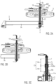
- Figur 1A und 1B
- eine seitliche Darstellung des landwirtschaftlichen Arbeitsgeräts in einer Arbeitsstellung und in einer Transportstellung;
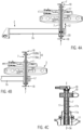
- Figur 2A bis 2C
- eine erste Ausführungsform der Einstellmechanik mit Rotor und Fahrwerk;
- Figur 3A und 3B
- eine zweite Ausführungsform der Einstellmechanik mit Rotor und Fahrwerk; und
- Figur 4A bis 4C
- eine dritte Ausführungsform der Einstellmechanik mit Rotor und Fahrwerk.
- Wie die
Figuren 1A und 1B erkennen lassen, umfasst das landwirtschaftliche Arbeitsgerät 1, bei dem es sich im Beispiel um einen gezogenen Kreiselschwader handelt, ein Fahrwerk 2, ein darauf gelagerten und um eine aufrechte Achse 3a drehbaren Rotor 3 mit Arbeitswerkzeugen 3b, bei denen es sich im Beispiel um Federzinken handelt, und eine hydraulische Aushebevorrichtung 4 zum Ausheben des Fahrwerks 2 zwischen einer in derFigur 1A beispielhaft dargestellten Arbeitsstellung 5 und einer in derFigur 1B beispielhaft dargestellten Transportstellung 6. Der Rotor 3 ist insbesondere der hintere Rotor eines Zweikreiselschwaders. - Zu erkennen ist ferner ein oberhalb des Rotors 3 auf prinzipiell bekannte Weise in einem Getriebekopf angeordneter Antrieb 3c für den Rotor 3. Die Fahrtrichtung 1a (hinter einem nicht dargestellten Schlepper) ist durch einen Pfeil in der
Figur 1B schematisch angedeutet. - Die Aushebevorrichtung 4 ist unterhalb des Rotors 3 angeordnet und an eine von oben nach unten durch den Rotor 3 geführte rohrförmige Hydraulikleitung 7 angeschlossen, beispielsweise mittels einer prinzipiell bekannten und daher nicht weiter beschriebenen Druckschlauchleitung.
- Das Arbeitsgerät 1 umfasst ferner eine Einstellmechanik 8 zur Höhenverstellung des Rotors 3 in der Arbeitsstellung 5 bezüglich des Fahrwerks 2. Hierzu umfasst die Einstellmechanik 8 zum einen ein die Hydraulikleitung 7 umgebendes oder abschnittsweise ausbildendes rohrförmiges Stellelement 8a und eine oberhalb des Rotors 3 angeordnete Betätigungsvorrichtung 8b zum Drehen des Stellelements 8a um die Achse 3a. Damit lässt sich eine in der Arbeitsstellung 5 wirksame Arbeitshöhe 9 des Rotors 3 einstellen, indem dieser bezüglich des insgesamt vollständig abgesenkten Fahrwerks 2 linear angehoben oder abgesenkt wird.
- Wie die
Figuren 2A bis 2C für eine erste bevorzugte Ausführungsform der Einstellmechanik 8 erkennen lassen, kann das rohrförmige Stellelement 8a als die Hydraulikleitung 7 umgebende Gewindebuchse 10 ausgebildet sein mit einem Innengewinde (ersten Stellgewinde) 10a, welches mit einem an der starren Hydraulikleitung 7 ausgebildeten Außengewinde 7a zusammenwirkt. Hierfür eignet sich beispielsweise ein Gewinde vom Typ M16 x 1,5_L. - Ferner kann die Gewindebuchse 10 ein Außengewinde (zweites Stellgewinde) 10b umfassen, welches mit einem an einer Rotorachse 11, einem Getriebegehäuse oder dergleichen feststehenden Struktur zur Lagerung des Rotors 3 ausgebildeten Innengewinde 11a zusammenwirkt. Hierfür eignet sich beispielsweise ein Gewinde vom Typ M22 x 1,5_R.
- Somit stützen sich Fahrwerk 2 und Rotor 3 gegenseitig über die Hydraulikleitung 7, die Gewindebuchse 10 und die nicht mitdrehende Rotorachse 11 oder dergleichen Tragstruktur ab.
- Das Innengewinde 10a und das Außengewinde 10b der Gewindebuchse 10 sind gegenläufig ausgebildet (beispielsweise außen ein Rechts- und innen ein Linksgewinde oder umgekehrt). Verdrehen der Gewindebuchse 10 bewirkt dann gleichzeitig einen ersten Teilhub 12a zwischen der Hydraulikleitung 7 und der Gewindebuchse 10 und einen zweiten Teilhub 12b zwischen der Gewindebuchse 10 und der Rotorachse 11. Die Teilhübe 12a, 12b addieren sich somit zu einem Einstellhub 12 zwischen der Rotorachse 11 mit dem daran vertikal festgelegten Rotor 3 zum einen und dem Rahmen 2 mit der diesbezüglich vertikal festgelegten Hydraulikleitung 7 zum anderen.
- Die Hydraulikleitung 7 dreht sich bei der Höhenverstellung dann insgesamt nicht mit, so dass Druckschläuche oder dergleichen am Arbeitsgerät 1 verlegte Leitungen auf unkomplizierte Weise direkt angeschlossen werden können.
- Der Einstellhub 12 beträgt beispielsweise 30 bis 150 mm. Dies lässt sich durch Kombination der Teilhübe 12a, 12b in kompakter Bauweise erreichen.
- In der
Figur 2A ist der Rotor 3 in seiner bezüglich des Fahrwerks 2 obersten Stellung und somit bei maximaler Arbeitshöhe 9 dargestellt, in derFigur 2B in seiner untersten Stellung und somit bei minimaler Arbeitshöhe 9. - In den
Figuren 2A und 2B ist dargestellt, dass die Betätigungsvorrichtung 8b ein Handrad 13 umfassen kann, welches koaxial zur Achse 3a an dem rohrförmigen Stellelement 8a / der Gewindebuchse 10 befestigt ist. In derFigur 2C fehlt das Handrad 13 der Übersichtlichkeit halber. - Die
Figuren 3A und 3B zeigen eine zweite bevorzugte Ausführungsform der Einstellmechanik 8, die sich im Wesentlichen von der zuvor beschriebenen Ausführungsform dadurch unterscheidet, dass sich die Gewindebuchse 10 und die Rotorachse 11 gegenseitig nicht durch Gewinde abstützen, sondern mittels eines vertikal (axial) festgelegten Lagers 14. Die Gewindebuchse 10 umfasst dann kein Außengewinde (zweites Stellgewinde) 10b. - Die Arbeitshöhe 9 des Rotors 3 bezüglich der Hydraulikleitung 7 und des Fahrwerks 2 wird dann entsprechend nur mittels des Innengewindes (ersten Stellgewindes) 10a der Gewindebuchse 10 und des Außengewindes 7a der starren Hydraulikleitung 7 verstellt, die sich dabei aber ebenso nicht mitdreht.
- Entsprechend ist der Einstellhub 12 bei dieser Ausführungsform identisch mit dem zuvor beschriebenen ersten Teilhub 12a.
- Wie die
Figuren 3A und 3B ferner schematisch erkennen lassen, kann die Betätigungsvorrichtung 8b ein Kegelradgetriebe 15 umfassen und/oder einen Antriebsmotor 16, um die Einstellmechanik 8 motorisch und gegebenenfalls automatisch zu betätigen. Diese Kombination ist aber nur als Beispiel zu verstehen. So ließe sich der Antriebsmotor 16 auch über ein anderweitiges Getriebe an das rohrförmige Stellelement 8a anbinden. Ebenso ließe sich das Kegelradgetriebe 15 auch manuell mittels einer Handkurbel oder dergleichen antreiben. - Dem Antriebsmotor 16 ist vorzugsweise eine elektronische Steuereinheit 16a zugeordnet, mit der sich beispielsweise infolge Programmierung unterschiedliche Arbeitshöhen 9 gezielt und reproduzierbar anfahren lassen. Die Bedienung wäre dann beispielsweise über Funk auch von einem Schlepper aus möglich. Es versteht sich, dass die Steuereinheit 16a nicht in Nachbarschaft zum Antriebsmotor 16 angeordnet sein muss.
- Ein Vorteil der zweiten Ausführungsform der Einstellmechanik 8 liegt darin, dass die Betätigungsvorrichtung 8b, also beispielsweise das Kegelradgetriebe 15 und der Antriebsmotor 16, aufgrund des fehlenden zweiten Teilhubs 12b in fester Höhenlage bezüglich des Rotors 3 und der Rotorachse 11 oder dergleichen Tragstruktur für den Rotor 3 angeordnet werden können. Dies kann bei einem motorischen Antrieb der Einstellmechanik 8 besonders vorteilhaft sein.
- Die
Figuren 4A bis 4C zeigen eine dritte bevorzugte Ausführungsform der Einstellmechanik 8, die sich von den zuvor beschriebenen Ausführungsformen im Wesentlichen dadurch unterscheidet, dass das rohrförmige Stellelement 8a als Hohlspindel 17 ausgebildet ist, die einen tragenden Abschnitt der Hydraulikleitung 7 ausbildet und sich bei der beschriebenen Höhenverstellung des Rotors 3 um die Achse 3a dreht. - Die starre Hohlspindel 17 umfasst ein Außengewinde (drittes Stellgewinde als Alternative zum ersten und gegebenenfalls zweiten Stellgewinde) 17a, das auf die zuvor beschriebene Weise bei der Höhenverstellung mit einem an der nicht mitdrehenden Rotorachse 11 oder dergleichen Tragstruktur ausgebildeten Innengewinde 11a zusammenwirkt. Entsprechend ist der Einstellhub 12 bei dieser Ausführungsform identisch mit dem zuvor beschriebenen zweiten Teilhub 12b.
- Bei dieser Ausführungsform umfasst die Hydraulikleitung 7 am oberen und unteren Ende der starren Hohlspindel 17 anschließende Drehdurchführungen 18, die jeweils einen druckdichten Anschluss zu bei der Höhenverstellung nicht mitdrehenden Druckschläuchen oder dergleichen Leitungen herstellen. Wie in der
Figur 4A angedeutet ist, wird die Hohlspindel 17 nach unten von einem Axiallager 20 am Träger 2a abgestützt. - Die Betätigungsvorrichtung 8b kann beispielsweise ein Schneckenradgetriebe 19 umfassen, das in den
Figuren 4A bis 4C lediglich beispielhaft und schematisch angedeutet ist. Dieses könnte beispielsweise mittels einer (nicht dargestellten) Handkurbel angetrieben werden oder motorisch. - Es versteht sich, dass die beschriebenen Ausführungsformen der Betätigungsvorrichtung 8b mit sämtlichen beschriebenen Ausführungsformen des rohrförmigen Stellelements 8a kombiniert werden können. Entscheidend ist hierbei, dass die Betätigungsvorrichtung 8b jeweils oberhalb des Rotors 3 angeordnet und somit für einen Bediener einfach und ergonomisch zugänglich ist oder einen einfachen motorischen Antrieb erlaubt. Zudem bewirkt das rohrförmige Stellelement 8a in sämtlichen Ausführungsformen eine lineare Höhenverstellung des Rotors 3 bezüglich des Fahrwerks 2 ohne Änderung der Rotorneigung, so dass schrittweise Überprüfung und Korrektur der vorgenommenen Höheneinstellung entbehrlich sind.
- Zudem ermöglichen die je nach Ausführungsform erfindungsgemäß vorhandenen Stellgewinde 10a und gegebenenfalls 10b zum einen oder 17a zum anderen jeweils eine Anpassung der Arbeitshöhe 9 bei in die Arbeitsstellung 5 abgesenktem Fahrwerk 2 und somit unter der vom Rotor 3 verursachten Eigenlast. Das Fahrwerk 2 muss daher für die Einstellung der Arbeitshöhe 9 nicht mehr ausgehoben und entlastet werden. Vielmehr können mittels der Einstellmechanik 8 vorgenommene Einstellungen der Arbeitshöhe 9 sofort in der Arbeitsstellung 5 kontrolliert und gegebenenfalls korrigiert werden.
- Wie insbesondere die
Figur 1B erkennen lässt, handelt es sich bei dem landwirtschaftlichen Arbeitsgerät 1 beispielsweise um einen Kreiselschwader, wobei dem Rotor 3 ein separates Fahrwerk 2 zugeordnet ist, welches einen prinzipiell bekannten Träger 2a zur Lagerung des Rotors 3 am Fahrwerk 2 und eine diesbezüglich schwenkbare Schwinge 2b umfasst mit daran gelagerten hinteren Laufrädern 2c. Diesen im Sinne eines Vierradfahrwerks zugeordnete vordere Laufräder 2d sind dagegen vorzugsweise in fester Höhenlage bezüglich des Trägers 2a gelagert. - Das Fahrwerk 2 umfasst die Aushebevorrichtung 4 mit wenigstens einem prinzipiell bekannten Hydraulikzylinder 4a, der an die Schwinge 2b gekoppelt ist, um diese bezüglich des Trägers 2a zu positionieren. Beim Abspreizen der Schwinge 2b wird der Träger 2a mit den vorderen Laufrädern 2d und dem Rotor 3 in die Transportstellung 6 ausgehoben, wobei die hinteren Laufräder 2c auf bekannte Weise permanent Bodenkontakt herstellen. Derartige Aushebevorrichtungen 4 sind bewährt und lassen sich einfach mit der erfindungsgemäßen Einstellmechanik 8 kombinieren.
- Besonders vorteilhaft ist eine derartige Kombination von Einstellmechanik 8 und Aushebevorrichtung 4 an einem gegebenenfalls hinteren Rotor 3 und Fahrwerk 2 eines gezogenen Kreiselschwaders mit wenigstens einem Rotor 3. In diesem Fall kann ein vergleichsweise weit von einem zugeordneten Schlepper (nicht dargestellt) entfernter Rotor 3 zum einen mit der Aushebevorrichtung 4 auf bewährte Weise in die Transportstellung 6 gestellt und zum anderen seine Arbeitshöhe 9 in der abgesenkten Arbeitsstellung 5 einfach und ergonomisch eingestellt werden.
- Alternativ zum beschriebenen Kreiselschwader ließe sich die beschriebene Einstellmechanik 8 auch an anderen landwirtschaftlichen Arbeitsgeräten mit entsprechend um im Wesentlichen aufrechte Achsen rotierenden Arbeitsgeräten und einer diesbezüglich koaxialen Hydraulikleitung einsetzen, beispielsweise an einem Kreiselheuer. Dieser kann beispielsweise in der
EP 0 627 878 A1 ,DE 29 30 152 A1 und/oderDE 196 19 172 A1 beschriebene Merkmale aufweisen.
Claims (15)
- Landwirtschaftliches Arbeitsgerät (1) umfassend: ein Fahrwerk (2); einen darauf gelagerten und um eine aufrechte Achse (3a) drehbaren Rotor (3) mit Arbeitswerkzeugen (3b); eine hydraulische Aushebevorrichtung (4) zum Ausheben des Fahrwerks zwischen einer Arbeitsstellung (5) und einer Transportstellung (6), wobei die Aushebevorrichtung unterhalb des Rotors angeordnet und an eine Hydraulikleitung (7) angeschlossen ist; und eine Einstellmechanik (8) zur Höhenverstellung des Rotors für die Arbeitsstellung, wobei die Einstellmechanik umfasst: ein rohrförmiges Stellelement (8a) mit wenigstens einem den Rotor und das Fahrwerk gegenseitig abstützenden axialen Stellgewinde; und eine oberhalb des Rotors angeordnete Betätigungsvorrichtung (8b) zum axialen und insbesondere werkzeuglosen Verdrehen des Stellelements, dadurch gekennzeichnet, dass die Hydraulikleitung (7) von oben nach unten durch den Rotor geführt ist und, dass das Stellelement (8a) die Hydraulikleitung umgibt oder abschnittsweise ausbildet.
- Landwirtschaftliches Arbeitsgerät nach Anspruch 1, wobei die Hydraulikleitung (7) zur gegenseitigen axialen Abstützung des Rotors (3) und des Fahrwerks (2) ausgebildet ist.
- Landwirtschaftliches Arbeitsgerät nach Anspruch 1 oder 2, wobei das Stellelement (8a) eine die Hydraulikleitung (7) umgebende Gewindebuchse (10) mit einem Innengewinde (10a) ist, das mit einem an der Hydraulikleitung ausgebildeten Außengewinde (7a) zusammenwirkt.
- Landwirtschaftliches Arbeitsgerät nach Anspruch 3, wobei die Gewindebuchse (10) ferner ein gegenläufiges Außengewinde (10b) aufweist, das mit einem Innengewinde (11a) zusammenwirkt, welches drehfest an einer Rotorachse (11) oder einem Gehäuse zur Lagerung des Rotors (3) angeordnet ist.
- Landwirtschaftliches Arbeitsgerät nach Anspruch 3, wobei die Gewindebuchse (10) auf ihrer Außenseite in bezüglich des Fahrwerks (2) fester Höhenlage drehbar an einer Rotorachse (11) oder einem Gehäuse zur Lagerung des Rotors (3) gelagert ist.
- Landwirtschaftliches Arbeitsgerät nach einem der vorigen Ansprüche, wobei die Hydraulikleitung (7) insgesamt mit dem Stellelement (8a) nicht mitdrehend angeordnet ist.
- Landwirtschaftliches Arbeitsgerät nach Anspruch 1 oder 2, wobei das Stellelement (8a) in Form einer Hohlspindel (17) als Bestandteil der Hydraulikleitung (7) ausgebildet ist, und wobei diese an ihren Enden hydraulische Drehdurchführungen (18) umfasst.
- Landwirtschaftliches Arbeitsgerät nach einem der vorigen Ansprüche, wobei die Betätigungsvorrichtung (8b) ein mit dem Stellelement (8a) verbundenes Kegelradgetriebe (15) oder Schneckenradgetriebe (19) umfasst.
- Landwirtschaftliches Arbeitsgerät nach einem der vorigen Ansprüche, wobei die Betätigungsvorrichtung (8b) einen elektrischen Antriebsmotor (16) umfasst.
- Landwirtschaftliches Arbeitsgerät nach einem der Ansprüche 1 bis 7, wobei die Betätigungsvorrichtung (8b) ein koaxial am Stellelement (8a) festgelegtes Handrad (13) umfasst.
- Landwirtschaftliches Arbeitsgerät nach wenigstens einem der vorigen Ansprüche, wobei die Einstellmechanik (8) zur Höhenverstellung unter einer in der Arbeitsstellung (5) einwirkenden Eigenlast des Rotors (3) ausgebildet ist.
- Landwirtschaftliches Arbeitsgerät nach wenigstens einem der vorigen Ansprüche, wobei das Fahrwerk (2) vordere und hintere Laufräder umfasst, und wobei die hinteren Laufräder (2c) in der Transportstellung (6) Bodenkontakt haben und die vorderen Laufräder (2d) dabei ausgehoben sind.
- Landwirtschaftliches Arbeitsgerät nach wenigstens einem der vorigen Ansprüche, wobei das Fahrwerk (2) eine Schwinge (2b) mit daran gelagerten Laufrädern (2c) umfasst, und wobei die Aushebevorrichtung (4) wenigstens einen Hydraulikzylinder (4a) zum Schwenken der Schwinge umfasst.
- Landwirtschaftliches Arbeitsgerät nach wenigstens einem der vorigen Ansprüche, welches ein gezogener Kreiselschwader ist.
- Landwirtschaftliches Arbeitsgerät nach Anspruch 14, wobei der Kreiselschwader einen vorderen und einen hinteren Rotor umfasst, und wobei das Fahrwerk (2) und die Einstellmechanik (8) dem hinteren Rotor (3) separat zugeordnet sind.
Priority Applications (3)
| Application Number | Priority Date | Filing Date | Title |
|---|---|---|---|
| EP22169386.4A EP4265085B1 (de) | 2022-04-22 | 2022-04-22 | Landwirtschaftliches arbeitsgerät |
| US18/302,949 US20230337585A1 (en) | 2022-04-22 | 2023-04-19 | Agricultural implement |
| CA3197622A CA3197622A1 (en) | 2022-04-22 | 2023-04-21 | Agricultural implement |
Applications Claiming Priority (1)
| Application Number | Priority Date | Filing Date | Title |
|---|---|---|---|
| EP22169386.4A EP4265085B1 (de) | 2022-04-22 | 2022-04-22 | Landwirtschaftliches arbeitsgerät |
Publications (3)
| Publication Number | Publication Date |
|---|---|
| EP4265085A1 EP4265085A1 (de) | 2023-10-25 |
| EP4265085C0 EP4265085C0 (de) | 2024-08-14 |
| EP4265085B1 true EP4265085B1 (de) | 2024-08-14 |
Family
ID=81346472
Family Applications (1)
| Application Number | Title | Priority Date | Filing Date |
|---|---|---|---|
| EP22169386.4A Active EP4265085B1 (de) | 2022-04-22 | 2022-04-22 | Landwirtschaftliches arbeitsgerät |
Country Status (3)
| Country | Link |
|---|---|
| US (1) | US20230337585A1 (de) |
| EP (1) | EP4265085B1 (de) |
| CA (1) | CA3197622A1 (de) |
Family Cites Families (6)
| Publication number | Priority date | Publication date | Assignee | Title |
|---|---|---|---|---|
| DE2930152C2 (de) | 1979-07-25 | 1984-01-26 | H. Niemeyer Söhne GmbH & Co KG, 4446 Hörstel | Heuwerbungsmaschine |
| FR2680947B1 (fr) * | 1991-09-10 | 1993-11-19 | Kuhn Sa | Machine de fenaison comportant des roulettes orientables. |
| DK168418B1 (da) | 1992-02-26 | 1994-03-28 | Taarup As Maskinfab | Høvender med mekanisk, simultan indstilling af riverotorvinkel og højde |
| DE29511268U1 (de) | 1995-07-12 | 1995-09-28 | Claas Saulgau Gmbh, 88348 Saulgau | Vorrichtung zum Einstellen des Neigungswinkels von Zinkenkreiseln |
| DE102009016519B4 (de) * | 2009-04-08 | 2021-06-17 | Claas Saulgau Gmbh | Heuwerbungsmaschine |
| DE102014014131A1 (de) * | 2014-09-23 | 2016-03-24 | Alois Pöttinger Maschinenfabrik Gmbh | Heuwerbungsmaschine |
-
2022
- 2022-04-22 EP EP22169386.4A patent/EP4265085B1/de active Active
-
2023
- 2023-04-19 US US18/302,949 patent/US20230337585A1/en active Pending
- 2023-04-21 CA CA3197622A patent/CA3197622A1/en active Pending
Also Published As
| Publication number | Publication date |
|---|---|
| EP4265085C0 (de) | 2024-08-14 |
| US20230337585A1 (en) | 2023-10-26 |
| EP4265085A1 (de) | 2023-10-25 |
| CA3197622A1 (en) | 2023-07-03 |
Similar Documents
| Publication | Publication Date | Title |
|---|---|---|
| DE69017362T2 (de) | Landmaschine mit verbesserter Aufhängungsvorrichtung der Arbeitswerkzeugeeinheit. | |
| EP1685988B1 (de) | Federungssystem für ein landwirtschaftliches Fahrzeug | |
| DE69207987T2 (de) | Heuwerbungsmaschine, insbesondere Schwader für geschnittenes Pflanzengut | |
| DE102018213212B4 (de) | Höhenverstellbare Kurvenbahn | |
| EP2633747B2 (de) | Striegeleinrichtung für eine landwirtschaftliche Bodenbearbeitungsvorrichtung | |
| DE1932229C3 (de) | Heuwerbungsmaschine | |
| DE3011212A1 (de) | Heuwerbungsmaschine | |
| EP0399256B1 (de) | Laufradsteuerung für ein landwirtschaftliches Gerät,insbesondere für eine Heuwerbungsmaschine | |
| EP0465819B1 (de) | Heuwerbungsmaschine | |
| EP2591653A1 (de) | Heuwerbungsmaschine | |
| DE69705013T2 (de) | Heuwerbungsmaschine | |
| EP1714603B1 (de) | Bodenreinigungsmaschine | |
| DE1507188C3 (de) | Stengelknicker | |
| EP1817953B1 (de) | Gerät zur Rasen-, Garten- bzw. Grundstückspflege und Arbeitshöheneinstellvorrichtung | |
| EP3092887B1 (de) | Heuwerbungsmaschine | |
| EP4265085A1 (de) | Landwirtschaftliches arbeitsgerät | |
| DE2652739A1 (de) | An einen traktor anbaubare vorrichtung zur bodenlockerung | |
| DE4219484B4 (de) | Heuwerbungsmaschine | |
| DE69008309T2 (de) | Verbesserung für landwirtschaftliche Maschinen insbesondere für Heuwerbungsmaschinen. | |
| EP4272527A1 (de) | Anbaugerät zur feldbearbeitung | |
| DE1940172C3 (de) | Heuwerbungsmaschine | |
| AT392718B (de) | Heuwerbungsmaschine | |
| EP1262098B1 (de) | Schwadgerät | |
| DE9414597U1 (de) | Gezogene Mähmaschine | |
| DE20012446U1 (de) | Landwirtschaftliche Maschine |
Legal Events
| Date | Code | Title | Description |
|---|---|---|---|
| STAA | Information on the status of an ep patent application or granted ep patent |
Free format text: STATUS: THE APPLICATION HAS BEEN PUBLISHED |
|
| PUAI | Public reference made under article 153(3) epc to a published international application that has entered the european phase |
Free format text: ORIGINAL CODE: 0009012 |
|
| AK | Designated contracting states |
Kind code of ref document: A1 Designated state(s): AL AT BE BG CH CY CZ DE DK EE ES FI FR GB GR HR HU IE IS IT LI LT LU LV MC MK MT NL NO PL PT RO RS SE SI SK SM TR |
|
| STAA | Information on the status of an ep patent application or granted ep patent |
Free format text: STATUS: REQUEST FOR EXAMINATION WAS MADE |
|
| 17P | Request for examination filed |
Effective date: 20231106 |
|
| RBV | Designated contracting states (corrected) |
Designated state(s): AL AT BE BG CH CY CZ DE DK EE ES FI FR GB GR HR HU IE IS IT LI LT LU LV MC MK MT NL NO PL PT RO RS SE SI SK SM TR |
|
| GRAP | Despatch of communication of intention to grant a patent |
Free format text: ORIGINAL CODE: EPIDOSNIGR1 |
|
| STAA | Information on the status of an ep patent application or granted ep patent |
Free format text: STATUS: GRANT OF PATENT IS INTENDED |
|
| RIC1 | Information provided on ipc code assigned before grant |
Ipc: A01D 78/10 20060101ALI20240229BHEP Ipc: A01B 63/16 20060101ALI20240229BHEP Ipc: A01B 63/00 20060101ALI20240229BHEP Ipc: A01B 33/10 20060101ALI20240229BHEP Ipc: A01B 33/06 20060101AFI20240229BHEP |
|
| INTG | Intention to grant announced |
Effective date: 20240318 |
|
| GRAS | Grant fee paid |
Free format text: ORIGINAL CODE: EPIDOSNIGR3 |
|
| GRAA | (expected) grant |
Free format text: ORIGINAL CODE: 0009210 |
|
| STAA | Information on the status of an ep patent application or granted ep patent |
Free format text: STATUS: THE PATENT HAS BEEN GRANTED |
|
| AK | Designated contracting states |
Kind code of ref document: B1 Designated state(s): AL AT BE BG CH CY CZ DE DK EE ES FI FR GB GR HR HU IE IS IT LI LT LU LV MC MK MT NL NO PL PT RO RS SE SI SK SM TR |
|
| REG | Reference to a national code |
Ref country code: GB Ref legal event code: FG4D Free format text: NOT ENGLISH |
|
| REG | Reference to a national code |
Ref country code: CH Ref legal event code: EP |
|
| REG | Reference to a national code |
Ref country code: DE Ref legal event code: R096 Ref document number: 502022001436 Country of ref document: DE |
|
| REG | Reference to a national code |
Ref country code: IE Ref legal event code: FG4D Free format text: LANGUAGE OF EP DOCUMENT: GERMAN |
|
| U01 | Request for unitary effect filed |
Effective date: 20240816 |
|
| U07 | Unitary effect registered |
Designated state(s): AT BE BG DE DK EE FI FR IT LT LU LV MT NL PT SE SI Effective date: 20240828 |
|
| PG25 | Lapsed in a contracting state [announced via postgrant information from national office to epo] |
Ref country code: NO Free format text: LAPSE BECAUSE OF FAILURE TO SUBMIT A TRANSLATION OF THE DESCRIPTION OR TO PAY THE FEE WITHIN THE PRESCRIBED TIME-LIMIT Effective date: 20241114 |
|
| PG25 | Lapsed in a contracting state [announced via postgrant information from national office to epo] |
Ref country code: PL Free format text: LAPSE BECAUSE OF FAILURE TO SUBMIT A TRANSLATION OF THE DESCRIPTION OR TO PAY THE FEE WITHIN THE PRESCRIBED TIME-LIMIT Effective date: 20240814 Ref country code: GR Free format text: LAPSE BECAUSE OF FAILURE TO SUBMIT A TRANSLATION OF THE DESCRIPTION OR TO PAY THE FEE WITHIN THE PRESCRIBED TIME-LIMIT Effective date: 20241115 |
|
| PG25 | Lapsed in a contracting state [announced via postgrant information from national office to epo] |
Ref country code: IS Free format text: LAPSE BECAUSE OF FAILURE TO SUBMIT A TRANSLATION OF THE DESCRIPTION OR TO PAY THE FEE WITHIN THE PRESCRIBED TIME-LIMIT Effective date: 20241214 |
|
| PG25 | Lapsed in a contracting state [announced via postgrant information from national office to epo] |
Ref country code: HR Free format text: LAPSE BECAUSE OF FAILURE TO SUBMIT A TRANSLATION OF THE DESCRIPTION OR TO PAY THE FEE WITHIN THE PRESCRIBED TIME-LIMIT Effective date: 20240814 |
|
| PG25 | Lapsed in a contracting state [announced via postgrant information from national office to epo] |
Ref country code: RS Free format text: LAPSE BECAUSE OF FAILURE TO SUBMIT A TRANSLATION OF THE DESCRIPTION OR TO PAY THE FEE WITHIN THE PRESCRIBED TIME-LIMIT Effective date: 20241114 Ref country code: ES Free format text: LAPSE BECAUSE OF FAILURE TO SUBMIT A TRANSLATION OF THE DESCRIPTION OR TO PAY THE FEE WITHIN THE PRESCRIBED TIME-LIMIT Effective date: 20240814 |
|
| PG25 | Lapsed in a contracting state [announced via postgrant information from national office to epo] |
Ref country code: RS Free format text: LAPSE BECAUSE OF FAILURE TO SUBMIT A TRANSLATION OF THE DESCRIPTION OR TO PAY THE FEE WITHIN THE PRESCRIBED TIME-LIMIT Effective date: 20241114 Ref country code: PL Free format text: LAPSE BECAUSE OF FAILURE TO SUBMIT A TRANSLATION OF THE DESCRIPTION OR TO PAY THE FEE WITHIN THE PRESCRIBED TIME-LIMIT Effective date: 20240814 Ref country code: NO Free format text: LAPSE BECAUSE OF FAILURE TO SUBMIT A TRANSLATION OF THE DESCRIPTION OR TO PAY THE FEE WITHIN THE PRESCRIBED TIME-LIMIT Effective date: 20241114 Ref country code: IS Free format text: LAPSE BECAUSE OF FAILURE TO SUBMIT A TRANSLATION OF THE DESCRIPTION OR TO PAY THE FEE WITHIN THE PRESCRIBED TIME-LIMIT Effective date: 20241214 Ref country code: HR Free format text: LAPSE BECAUSE OF FAILURE TO SUBMIT A TRANSLATION OF THE DESCRIPTION OR TO PAY THE FEE WITHIN THE PRESCRIBED TIME-LIMIT Effective date: 20240814 Ref country code: GR Free format text: LAPSE BECAUSE OF FAILURE TO SUBMIT A TRANSLATION OF THE DESCRIPTION OR TO PAY THE FEE WITHIN THE PRESCRIBED TIME-LIMIT Effective date: 20241115 Ref country code: ES Free format text: LAPSE BECAUSE OF FAILURE TO SUBMIT A TRANSLATION OF THE DESCRIPTION OR TO PAY THE FEE WITHIN THE PRESCRIBED TIME-LIMIT Effective date: 20240814 |
|
| PG25 | Lapsed in a contracting state [announced via postgrant information from national office to epo] |
Ref country code: SM Free format text: LAPSE BECAUSE OF FAILURE TO SUBMIT A TRANSLATION OF THE DESCRIPTION OR TO PAY THE FEE WITHIN THE PRESCRIBED TIME-LIMIT Effective date: 20240814 |
|
| PG25 | Lapsed in a contracting state [announced via postgrant information from national office to epo] |
Ref country code: CZ Free format text: LAPSE BECAUSE OF FAILURE TO SUBMIT A TRANSLATION OF THE DESCRIPTION OR TO PAY THE FEE WITHIN THE PRESCRIBED TIME-LIMIT Effective date: 20240814 |
|
| PG25 | Lapsed in a contracting state [announced via postgrant information from national office to epo] |
Ref country code: SK Free format text: LAPSE BECAUSE OF FAILURE TO SUBMIT A TRANSLATION OF THE DESCRIPTION OR TO PAY THE FEE WITHIN THE PRESCRIBED TIME-LIMIT Effective date: 20240814 |
|
| U20 | Renewal fee for the european patent with unitary effect paid |
Year of fee payment: 4 Effective date: 20250425 |
|
| PLBE | No opposition filed within time limit |
Free format text: ORIGINAL CODE: 0009261 |
|
| STAA | Information on the status of an ep patent application or granted ep patent |
Free format text: STATUS: NO OPPOSITION FILED WITHIN TIME LIMIT |
|
| 26N | No opposition filed |
Effective date: 20250515 |
|
| REG | Reference to a national code |
Ref country code: CH Ref legal event code: H13 Free format text: ST27 STATUS EVENT CODE: U-0-0-H10-H13 (AS PROVIDED BY THE NATIONAL OFFICE) Effective date: 20251125 |
|
| PG25 | Lapsed in a contracting state [announced via postgrant information from national office to epo] |
Ref country code: MC Free format text: LAPSE BECAUSE OF FAILURE TO SUBMIT A TRANSLATION OF THE DESCRIPTION OR TO PAY THE FEE WITHIN THE PRESCRIBED TIME-LIMIT Effective date: 20240814 |
|
| PG25 | Lapsed in a contracting state [announced via postgrant information from national office to epo] |
Ref country code: CH Free format text: LAPSE BECAUSE OF NON-PAYMENT OF DUE FEES Effective date: 20250430 |
|
| PG25 | Lapsed in a contracting state [announced via postgrant information from national office to epo] |
Ref country code: IE Free format text: LAPSE BECAUSE OF NON-PAYMENT OF DUE FEES Effective date: 20250422 |
|
| PG25 | Lapsed in a contracting state [announced via postgrant information from national office to epo] |
Ref country code: RO Free format text: LAPSE BECAUSE OF FAILURE TO SUBMIT A TRANSLATION OF THE DESCRIPTION OR TO PAY THE FEE WITHIN THE PRESCRIBED TIME-LIMIT Effective date: 20240814 |