EP4265085B1 - Appareil de travail agricole - Google Patents
Appareil de travail agricole Download PDFInfo
- Publication number
- EP4265085B1 EP4265085B1 EP22169386.4A EP22169386A EP4265085B1 EP 4265085 B1 EP4265085 B1 EP 4265085B1 EP 22169386 A EP22169386 A EP 22169386A EP 4265085 B1 EP4265085 B1 EP 4265085B1
- Authority
- EP
- European Patent Office
- Prior art keywords
- rotor
- agricultural implement
- implement according
- chassis
- hydraulic line
- Prior art date
- Legal status (The legal status is an assumption and is not a legal conclusion. Google has not performed a legal analysis and makes no representation as to the accuracy of the status listed.)
- Active
Links
Images


Classifications
-
- A—HUMAN NECESSITIES
- A01—AGRICULTURE; FORESTRY; ANIMAL HUSBANDRY; HUNTING; TRAPPING; FISHING
- A01D—HARVESTING; MOWING
- A01D78/00—Haymakers with tines moving with respect to the machine
- A01D78/08—Haymakers with tines moving with respect to the machine with tine-carrying rotary heads or wheels
- A01D78/10—Haymakers with tines moving with respect to the machine with tine-carrying rotary heads or wheels the tines rotating about a substantially vertical axis
- A01D78/1007—Arrangements to facilitate transportation specially adapted therefor
-
- A—HUMAN NECESSITIES
- A01—AGRICULTURE; FORESTRY; ANIMAL HUSBANDRY; HUNTING; TRAPPING; FISHING
- A01B—SOIL WORKING IN AGRICULTURE OR FORESTRY; PARTS, DETAILS, OR ACCESSORIES OF AGRICULTURAL MACHINES OR IMPLEMENTS, IN GENERAL
- A01B33/00—Tilling implements with rotary driven tools, e.g. in combination with fertiliser distributors or seeders, with grubbing chains, with sloping axles, with driven discs
- A01B33/06—Tilling implements with rotary driven tools, e.g. in combination with fertiliser distributors or seeders, with grubbing chains, with sloping axles, with driven discs with tools on vertical or steeply-inclined shaft
-
- A—HUMAN NECESSITIES
- A01—AGRICULTURE; FORESTRY; ANIMAL HUSBANDRY; HUNTING; TRAPPING; FISHING
- A01B—SOIL WORKING IN AGRICULTURE OR FORESTRY; PARTS, DETAILS, OR ACCESSORIES OF AGRICULTURAL MACHINES OR IMPLEMENTS, IN GENERAL
- A01B33/00—Tilling implements with rotary driven tools, e.g. in combination with fertiliser distributors or seeders, with grubbing chains, with sloping axles, with driven discs
- A01B33/08—Tools; Details, e.g. adaptations of transmissions or gearings
- A01B33/10—Structural or functional features of the tools ; Theoretical aspects of the cutting action
- A01B33/106—Structural or functional features of the tools ; Theoretical aspects of the cutting action the rotating shaft being oriented vertically or steeply inclined
-
- A—HUMAN NECESSITIES
- A01—AGRICULTURE; FORESTRY; ANIMAL HUSBANDRY; HUNTING; TRAPPING; FISHING
- A01B—SOIL WORKING IN AGRICULTURE OR FORESTRY; PARTS, DETAILS, OR ACCESSORIES OF AGRICULTURAL MACHINES OR IMPLEMENTS, IN GENERAL
- A01B63/00—Lifting or adjusting devices or arrangements for agricultural machines or implements
- A01B63/002—Devices for adjusting or regulating the position of tools or wheels
- A01B63/008—Vertical adjustment of tools
-
- A—HUMAN NECESSITIES
- A01—AGRICULTURE; FORESTRY; ANIMAL HUSBANDRY; HUNTING; TRAPPING; FISHING
- A01B—SOIL WORKING IN AGRICULTURE OR FORESTRY; PARTS, DETAILS, OR ACCESSORIES OF AGRICULTURAL MACHINES OR IMPLEMENTS, IN GENERAL
- A01B63/00—Lifting or adjusting devices or arrangements for agricultural machines or implements
- A01B63/14—Lifting or adjusting devices or arrangements for agricultural machines or implements for implements drawn by animals or tractors
- A01B63/16—Lifting or adjusting devices or arrangements for agricultural machines or implements for implements drawn by animals or tractors with wheels adjustable relatively to the frame
-
- A—HUMAN NECESSITIES
- A01—AGRICULTURE; FORESTRY; ANIMAL HUSBANDRY; HUNTING; TRAPPING; FISHING
- A01D—HARVESTING; MOWING
- A01D78/00—Haymakers with tines moving with respect to the machine
- A01D78/08—Haymakers with tines moving with respect to the machine with tine-carrying rotary heads or wheels
- A01D78/10—Haymakers with tines moving with respect to the machine with tine-carrying rotary heads or wheels the tines rotating about a substantially vertical axis
- A01D78/105—Ground support for rotors
-
- A—HUMAN NECESSITIES
- A01—AGRICULTURE; FORESTRY; ANIMAL HUSBANDRY; HUNTING; TRAPPING; FISHING
- A01D—HARVESTING; MOWING
- A01D78/00—Haymakers with tines moving with respect to the machine
- A01D78/08—Haymakers with tines moving with respect to the machine with tine-carrying rotary heads or wheels
- A01D78/10—Haymakers with tines moving with respect to the machine with tine-carrying rotary heads or wheels the tines rotating about a substantially vertical axis
- A01D78/1071—Having only one rotor
Definitions
- the invention relates to an agricultural implement according to the preamble of claim 1.
- a generic agricultural implement is known, for example, in the form of a towed rotary swather.
- This can comprise a front and a rear rotor, each with working tools designed as spring tines, whereby the rotors can be mounted on separate chassis.
- the chassis of the rear rotor must then be lifted separately from a working position with lowered working tools to a transport position with raised working tools.
- Suitable four-wheel chassis for this comprise front and rear running wheels, whereby the rear ones make contact with the ground in the transport position and the front ones are then lifted.
- Lifting is preferably carried out using a swing arm construction that is adjusted by a hydraulic cylinder. Since the hydraulic cylinder is located below the rotor assigned to the chassis, the hydraulic cylinder is usually operated via a hydraulic line that runs from top to bottom through the axis of rotation of the rotor.
- the working height of the rotor (height in the working position in relation to the surface being driven on) is set on the type of implement or rotary rake by adjusting the positions of the running wheels on the chassis. To do this, the front and rear running wheels of the chassis must be adjusted separately, and this is only possible when the chassis is unloaded, i.e. in the transport position. In addition, the height adjustment must be carried out manually using tools underneath the rotor.
- DE10 2014 014131 discloses a haymaking machine with at least one rake rotor which can be driven in rotation about an upright rake rotor axis and is supported on the ground by a sensor chassis, wherein a height adjustment device is provided for adjusting the height of the sensor chassis along the rake rotor axis.
- the agricultural implement comprises a chassis, a rotor mounted thereon and rotatable about an upright axis with working tools and a hydraulic lifting device for lifting the chassis between a working position and a transport position, in which the rotor is raised further in relation to the ground being driven on than in the working position.
- the lifting device is arranged below the rotor and is connected to a hydraulic line that runs from top to bottom through the rotor.
- the agricultural implement comprises an adjustment mechanism for adjusting the height of the rotor for the working position, or in other words for adjusting the working height of the rotor.
- the adjustment mechanism comprises a tubular adjusting element that surrounds the hydraulic line or forms it in sections, with at least one axial adjusting thread that supports the rotor and the chassis in a mutually supporting manner, and an actuating device arranged above the rotor for axial and, in particular, tool-free rotation of the adjusting element.
- the adjusting element can be rotated by the actuating device about the axis of rotation of the rotor, for example by means of a handwheel, a crank or a drive motor, in order to adjust the height of the rotor in the working position with respect to the chassis that supports it by means of the adjusting thread.
- the working height of the rotor can therefore be ergonomically adjusted on its top using the operating device.
- the height adjustment of the rotor is relative to the chassis as a whole, so that the front and rear wheels of a four-wheel chassis no longer have to be adjusted separately. This makes it possible to adjust the height of the rotor without changing its inclination at the same time. Repeated corrections are therefore generally no longer necessary when adjusting the height.
- the hydraulic line is preferably designed to be rigid for axially supporting the rotor and the chassis, or to provide mutual support. This enables a compact design.
- the tubular adjusting element enables, for example, a height adjustment of 30 to 150 mm.
- Types M22 x 1.5 and/or M16 x 1.5 are suitable as adjusting threads.
- a combination of different thread pitches and/or a combination of right-hand and left-hand threads is also possible.
- the tubular adjusting element is a threaded bushing surrounding the hydraulic line with an internal thread (first adjusting thread) that interacts with an external thread formed on the hydraulic line.
- first adjusting thread an internal thread
- an axial stroke of the hydraulic line can be achieved depending on the thread pitch without the hydraulic line rotating with the threaded bushing. This enables a structurally simple connection of the hydraulic line above and below the rotor and adjustability under load.
- the threaded bushing further comprises an opposing external thread (second adjusting thread) which cooperates with an internal thread which is arranged in a rotationally fixed manner on a rotor axis or a housing which is designed to support the rotor.
- second adjusting thread an opposing external thread
- the internal thread and the external thread of the threaded bushing are designed to run in opposite directions to one another.
- the partial strokes caused by the thread pitches of the internal and external threads of the threaded bushing when they rotate add up to a total stroke of the height adjustment, which enables a compact design and quick height adjustment.
- the threaded bushing is mounted on its outside at a fixed height on a rotor axis or a housing, which is also designed to support the rotor.
- the actuating device can thus be arranged relatively easily in the area of the rotor, for example on the so-called rotor head. This also favors a motor drive of the actuating device.
- the hydraulic line is attached to the actuator in a non-rotating manner. This facilitates the hydraulic connection on both sides to permanently installed pressure hoses or the like.
- the actuating element is designed in the form of a hollow spindle (rigid tubular spindle with external thread) as part of the hydraulic line, which then comprises hydraulic rotary unions at its ends.
- the rigid hydraulic line rotates the height adjustment of the rotor then inevitably follows.
- hydraulic rotary unions enable a non-rotating connection of the hydraulic line on the top and bottom of the rotor to pressure hose lines or similar lines, for example to the hydraulic lifting device.
- the supporting actuating element and hydraulic line can thus be provided relatively easily and in a space-saving manner in the form of the hollow spindle.
- the actuating device comprises a bevel gear or worm gear connected to the actuating element. This enables a comparatively simple manual height adjustment by means of a hand crank or a motor drive.
- the actuating device preferably comprises an electric drive motor. This enables flexible and quick height adjustment of the rotor, for example in different working situations, and makes manual adjustment of the working height unnecessary. In addition, previously saved working heights can be set using an associated electronic control unit.
- the actuating device comprises a handwheel fixed coaxially to the actuating element. This is comparatively compact and can advantageously be permanently attached to the rotor head.
- the adjustment mechanism for height adjustment/setting the working height is designed to be under the rotor's own weight in the working position. It is then no longer necessary to relieve the chassis or lift it out to adjust the height of the rotor. Set working heights can therefore be checked quickly and easily.
- the height setting can be displayed above the rotor using a scale that can be read from a tractor, for example, and thus by its driver from a distance.
- the chassis preferably comprises front and rear wheels, i.e. it is designed as a four-wheel chassis, with the rear wheels in contact with the ground in the transport position and the front wheels being raised. This makes it possible to provide an effective lifting device that works particularly advantageously with the adjustment mechanism described.
- the chassis comprises a swing arm with wheels mounted thereon, wherein the lifting device comprises at least one hydraulic cylinder for pivoting the swing arm.
- the lifting device comprises at least one hydraulic cylinder for pivoting the swing arm.
- This also serves as a lifting device that can be combined particularly well with the adjustment mechanism according to the invention.
- the agricultural implement is a towed rotary swather.
- This then preferably comprises a front and a rear rotor, wherein the described Chassis and the adjustment mechanism are assigned separately to the rear rotor. Since the adjustment mechanism on the rear rotor is relatively far away from an associated tractor, it works particularly advantageously together with the lifting device.
- the agricultural implement according to at least one of the described embodiments could, for example, also be a towed rotary tedder.
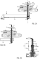
- the agricultural implement 1 which in the example is a towed rotary swather, comprises a chassis 2, a rotor 3 mounted thereon and rotatable about an upright axis 3a with working tools 3b, which in the example are spring tines, and a hydraulic lifting device 4 for lifting the chassis 2 between a Figure 1A exemplary working position 5 and one in the Figure 1B transport position 6 shown as an example.
- the rotor 3 is in particular the rear rotor of a two-rotor rake.
- a drive 3c for the rotor 3 can be seen, which is arranged in a gear head above the rotor 3 in a manner known in principle.
- the direction of travel 1a (behind a tractor not shown) is indicated by an arrow in the Figure 1B indicated schematically.
- the lifting device 4 is arranged below the rotor 3 and is connected to a tubular hydraulic line 7 which runs from top to bottom through the rotor 3, for example by means of a pressure hose line which is known in principle and therefore not described further.
- the working device 1 further comprises an adjustment mechanism 8 for adjusting the height of the rotor 3 in the working position 5 with respect to the chassis 2.
- the adjustment mechanism 8 comprises a tubular adjusting element 8a surrounding the hydraulic line 7 or forming it in sections and an actuating device 8b arranged above the rotor 3 for rotating the adjusting element 8a about the axis 3a. This enables a height adjustment in the working position 5 Set the effective working height 9 of the rotor 3 by raising or lowering it linearly with respect to the completely lowered chassis 2.
- the tubular adjusting element 8a can be designed as a threaded bushing 10 surrounding the hydraulic line 7 with an internal thread (first adjusting thread) 10a, which interacts with an external thread 7a formed on the rigid hydraulic line 7.
- a thread of type M16 x 1.5_L is suitable for this, for example.
- the threaded bushing 10 can comprise an external thread (second adjusting thread) 10b, which interacts with an internal thread 11a formed on a rotor axis 11, a gear housing or the like fixed structure for supporting the rotor 3.
- a thread of the type M22 x 1.5_R is suitable for this purpose, for example.
- chassis 2 and the rotor 3 support each other via the hydraulic line 7, the threaded bushing 10 and the non-rotating rotor axis 11 or similar supporting structure.
- the internal thread 10a and the external thread 10b of the threaded bushing 10 are designed in opposite directions (for example a right-hand thread on the outside and a left-hand thread on the inside, or vice versa). Turning the threaded bushing 10 then simultaneously causes a first partial stroke 12a between the hydraulic line 7 and the threaded bushing 10 and a second partial stroke 12b between the threaded bushing 10 and the rotor axis 11.
- the partial strokes 12a, 12b thus add up to an adjustment stroke 12 between the rotor axis 11 with the rotor 3 vertically attached to it on the one hand and the frame 2 with the hydraulic line 7 vertically attached to it on the other.
- the hydraulic line 7 then does not rotate as a whole during the height adjustment, so that pressure hoses or similar lines laid on the working device 1 can be connected directly in an uncomplicated manner.
- the adjustment stroke 12 is, for example, 30 to 150 mm. This can be achieved by combining the partial strokes 12a, 12b in a compact design.
- the actuating device 8b can comprise a handwheel 13 which is attached coaxially to the axis 3a on the tubular actuating element 8a / the threaded bushing 10.
- handwheel 13 is missing.
- FIGS. 3A and 3B show a second preferred embodiment of the adjustment mechanism 8, which differs essentially from the previously described embodiment in that the threaded bushing 10 and the rotor axis 11 do not support each other by threads, but by means of a vertically (axially) fixed bearing 14.
- the threaded bushing 10 then does not comprise an external thread (second adjusting thread) 10b.
- the working height 9 of the rotor 3 with respect to the hydraulic line 7 and the chassis 2 is then adjusted accordingly only by means of the internal thread (first adjusting thread) 10a of the threaded bushing 10 and the external thread 7a of the rigid hydraulic line 7, which, however, does not rotate in the process.
- the adjustment stroke 12 in this embodiment is identical to the previously described first partial stroke 12a.
- the actuating device 8b can comprise a bevel gear 15 and/or a drive motor 16 in order to actuate the adjustment mechanism 8 by motor and, if necessary, automatically.
- the drive motor 16 could also be connected to the tubular actuating element 8a via another gear.
- the bevel gear 15 could also be driven manually by means of a hand crank or the like.
- the drive motor 16 is preferably assigned an electronic control unit 16a, with which different working heights 9 can be approached in a targeted and reproducible manner, for example as a result of programming. Operation would then also be possible, for example, via radio from a tractor. It goes without saying that the control unit 16a does not have to be arranged in the vicinity of the drive motor 16.
- An advantage of the second embodiment of the adjustment mechanism 8 is that the actuating device 8b, for example the bevel gear 15 and the drive motor 16, can be arranged at a fixed height with respect to the rotor 3 and the rotor axis 11 or the like supporting structure for the rotor 3 due to the lack of a second partial stroke 12b. This can be particularly advantageous when the adjustment mechanism 8 is motor-driven.
- FIGS. 4A to 4C show a third preferred embodiment of the adjustment mechanism 8, which differs from the previously described embodiments essentially in that the tubular adjusting element 8a is designed as a hollow spindle 17, which forms a supporting section of the hydraulic line 7 and rotates about the axis 3a during the described height adjustment of the rotor 3.
- the rigid hollow spindle 17 comprises an external thread (third adjusting thread as an alternative to the first and possibly second adjusting thread) 17a, which interacts in the manner described above with an internal thread 11a formed on the non-rotating rotor axis 11 or the like support structure during the height adjustment. Accordingly, the adjustment stroke 12 in this embodiment is identical to the second partial stroke 12b described above.
- the hydraulic line 7 comprises rotary unions 18 at the upper and lower ends of the rigid hollow spindle 17, which each provide a pressure-tight connection to pressure hoses or similar lines that do not rotate during the height adjustment.
- the hollow spindle 17 is supported downwards by an axial bearing 20 on the carrier 2a.
- the actuating device 8b may, for example, comprise a worm gear 19 which is Figures 4A to 4C is only indicated schematically and by way of example. This could be driven by means of a hand crank (not shown) or by a motor.
- the described embodiments of the actuating device 8b can be combined with all described embodiments of the tubular adjusting element 8a.
- the decisive factor here is that the actuating device 8b is arranged above the rotor 3 and is therefore easily and ergonomically accessible for an operator or allows a simple motor drive.
- the tubular adjusting element 8a in all embodiments causes a linear height adjustment of the rotor 3 with respect to the chassis 2 without changing the rotor inclination, so that step-by-step checking and correction of the height adjustment made is unnecessary.
- the adjusting threads 10a and possibly 10b on the one hand or 17a on the other hand which are present according to the embodiment according to the invention, enable the working height 9 to be adjusted when the chassis 2 is lowered into the working position 5 and thus under the dead load caused by the rotor 3.
- the chassis 2 therefore no longer has to be lifted out and relieved in order to adjust the working height 9.
- settings of the working height 9 made using the adjustment mechanism 8 can be checked immediately in the working position 5 and corrected if necessary.
- the agricultural implement 1 is, for example, a rotary swather, with the rotor 3 being assigned a separate chassis 2, which comprises a carrier 2a known in principle for mounting the rotor 3 on the chassis 2 and a swing arm 2b which can be pivoted in this respect with rear wheels 2c.
- Front wheels 2d assigned to these in the sense of a four-wheel chassis are, however, preferably mounted at a fixed height with respect to the carrier 2a.
- the chassis 2 comprises the lifting device 4 with at least one hydraulic cylinder 4a, which is known in principle and is coupled to the swing arm 2b in order to position it with respect to the carrier 2a.
- the lifting device 4 with at least one hydraulic cylinder 4a, which is known in principle and is coupled to the swing arm 2b in order to position it with respect to the carrier 2a.
- the swing arm 2b is spread, the carrier 2a with the front wheels 2d and the rotor 3 is lifted into the transport position 6, with the rear wheels 2c making permanent contact with the ground in a known manner.
- Such lifting devices 4 are tried and tested and can be easily combined with the adjustment mechanism 8 according to the invention.
- Such a combination of adjustment mechanism 8 and lifting device 4 on a possibly rear rotor 3 and chassis 2 of a towed rotary swather with at least one rotor 3 is particularly advantageous.
- a rotor 3 that is comparatively far away from an associated tractor (not shown) can, on the one hand, be placed in the transport position 6 with the lifting device 4 in a proven manner and, on the other hand, its working height 9 in the lowered working position 5 can be adjusted easily and ergonomically.
- the described adjustment mechanism 8 could also be used on other agricultural implements with implements rotating around essentially upright axes and a coaxial hydraulic line, for example on a rotary hay rake. This can be used, for example, in the EP 0 627 878 A1 , EN 29 30 152 A1 and/or DE 196 19 172 A1 have the characteristics described.
Landscapes
- Life Sciences & Earth Sciences (AREA)
- Environmental Sciences (AREA)
- Engineering & Computer Science (AREA)
- Mechanical Engineering (AREA)
- Soil Sciences (AREA)
- Zoology (AREA)
- Agricultural Machines (AREA)
Claims (15)
- Outil de travail agricole (1) comprenant : un châssis (2) ; un rotor (3) monté sur celui-ci et pouvant tourner autour d'un axe vertical (3a), avec des outils de travail (3b) ; un dispositif de levage hydraulique (4) pour lever le châssis entre une position de travail (5) et une position de transport (6), le dispositif de levage étant disposé sous le rotor et étant raccordé à une conduite hydraulique (7) ; et un mécanisme de réglage (8) pour régler la hauteur du rotor pour la position de travail, le mécanisme de réglage comprenant : un élément de réglage tubulaire (8a) avec au moins un filetage de réglage axial soutenant mutuellement le rotor et le mécanisme de roulement ; et un dispositif d'actionnement (8b) disposé au-dessus du rotor pour la rotation axiale et en particulier sans outil de l'élément de réglage, caractérisé en ce que la conduite hydraulique (7) est guidée de haut en bas à travers le rotor et en ce que l'élément de réglage (8a) entoure la conduite hydraulique ou par tronçons lui donne la forme.
- Outil de travail agricole selon la revendication 1, dans lequel la conduite hydraulique (7) est conçue pour le soutien axial mutuel du rotor (3) et du châssis (2).
- Outil de travail agricole selon la revendication 1 ou 2, dans lequel l'élément de réglage (8a) est une douille filetée (10) entourant la conduite hydraulique (7) et comportant un filetage intérieur (10a) qui agit conjointement avec un filetage extérieur (7a) formé sur la conduite hydraulique.
- Outil agricole selon la revendication 3, dans lequel la douille filetée (10) comprend en outre un filetage extérieur (10b) tournant en sens inverse, qui coopère avec un filetage intérieur (11a), qui est disposé sur un axe de rotor de manière à ne pas pouvoir tourner (11) ou sur un boîtier pour le logement du rotor (3).
- Outil de travail agricole selon la revendication 3, dans lequel la douille filetée (10) est montée sur son côté extérieur de manière à pouvoir tourner sur un axe de rotor (11) ou sur un boîtier pour le montage du rotor (3) dans une position en hauteur fixe par rapport au châssis (2) .
- Outil de travail agricole selon l'une des revendications précédentes, dans lequel la conduite hydraulique (7) est disposée globalement par rapport à l'élément de réglage (8a) de manière à ne pas tourner avec lui.
- Outil de travail agricole selon la revendication 1 ou 2, dans lequel l'élément de réglage (8a) est réalisé sous la forme d'une broche creuse (17) faisant partie intégrante de la conduite hydraulique (7), et dans lequel celle-ci comprend des passages rotatifs hydrauliques (18) à ses extrémités.
- Outil agricole selon l'une des revendications précédentes, dans lequel le dispositif d'actionnement (8b) comprend un engrenage conique (15) ou un engrenage à vis sans fin (19) relié à l'élément de réglage (8a).
- Outil agricole selon l'une quelconque des revendications précédentes, dans lequel le dispositif d'actionnement (8b) comprend un moteur d'entraînement électrique (16).
- Outil de travail agricole selon l'une des revendications 1 à 7, dans lequel le dispositif d'actionnement (8b) comprend un volant (13) fixé coaxialement à l'élément de réglage (8a).
- Outil agricole selon au moins l'une des revendications précédentes, dans lequel le mécanisme de réglage (8) est conçu pour le réglage en hauteur sous une charge propre du rotor (3) agissant dans la position de travail (5).
- Outil agricole selon au moins l'une des revendications précédentes, dans lequel le châssis (2) comprend des roues porteuses avant et arrière, et dans lequel les roues porteuses arrière (2c) sont en contact avec le sol dans la position de transport (6) tandis que les roues porteuses avant (2d) sont relevées.
- Outil agricole selon au moins l'une des revendications précédentes, dans lequel le châssis (2) comprend un bras oscillant (2b) sur lequel sont montées des roues (2c), et dans lequel le dispositif de relevage (4) comprend au moins un vérin hydraulique (4a) pour faire pivoter le bras oscillant.
- Outil agricole selon au moins l'une des revendications précédentes, qui est une andaineuse rotative tractée.
- Outil de travail agricole selon la revendication 14, dans lequel l'andaineuse rotative comprend un rotor avant et un rotor arrière, et dans lequel le châssis (2) et le mécanisme de réglage (8) sont associés séparément au rotor arrière (3).
Priority Applications (3)
| Application Number | Priority Date | Filing Date | Title |
|---|---|---|---|
| EP22169386.4A EP4265085B1 (fr) | 2022-04-22 | 2022-04-22 | Appareil de travail agricole |
| US18/302,949 US20230337585A1 (en) | 2022-04-22 | 2023-04-19 | Agricultural implement |
| CA3197622A CA3197622A1 (fr) | 2022-04-22 | 2023-04-21 | Appareil agricole |
Applications Claiming Priority (1)
| Application Number | Priority Date | Filing Date | Title |
|---|---|---|---|
| EP22169386.4A EP4265085B1 (fr) | 2022-04-22 | 2022-04-22 | Appareil de travail agricole |
Publications (3)
| Publication Number | Publication Date |
|---|---|
| EP4265085A1 EP4265085A1 (fr) | 2023-10-25 |
| EP4265085C0 EP4265085C0 (fr) | 2024-08-14 |
| EP4265085B1 true EP4265085B1 (fr) | 2024-08-14 |
Family
ID=81346472
Family Applications (1)
| Application Number | Title | Priority Date | Filing Date |
|---|---|---|---|
| EP22169386.4A Active EP4265085B1 (fr) | 2022-04-22 | 2022-04-22 | Appareil de travail agricole |
Country Status (3)
| Country | Link |
|---|---|
| US (1) | US20230337585A1 (fr) |
| EP (1) | EP4265085B1 (fr) |
| CA (1) | CA3197622A1 (fr) |
Family Cites Families (6)
| Publication number | Priority date | Publication date | Assignee | Title |
|---|---|---|---|---|
| DE2930152C2 (de) | 1979-07-25 | 1984-01-26 | H. Niemeyer Söhne GmbH & Co KG, 4446 Hörstel | Heuwerbungsmaschine |
| FR2680947B1 (fr) * | 1991-09-10 | 1993-11-19 | Kuhn Sa | Machine de fenaison comportant des roulettes orientables. |
| DK168418B1 (da) | 1992-02-26 | 1994-03-28 | Taarup As Maskinfab | Høvender med mekanisk, simultan indstilling af riverotorvinkel og højde |
| DE29511268U1 (de) | 1995-07-12 | 1995-09-28 | Claas Saulgau Gmbh, 88348 Saulgau | Vorrichtung zum Einstellen des Neigungswinkels von Zinkenkreiseln |
| DE102009016519B4 (de) * | 2009-04-08 | 2021-06-17 | Claas Saulgau Gmbh | Heuwerbungsmaschine |
| DE102014014131A1 (de) * | 2014-09-23 | 2016-03-24 | Alois Pöttinger Maschinenfabrik Gmbh | Heuwerbungsmaschine |
-
2022
- 2022-04-22 EP EP22169386.4A patent/EP4265085B1/fr active Active
-
2023
- 2023-04-19 US US18/302,949 patent/US20230337585A1/en active Pending
- 2023-04-21 CA CA3197622A patent/CA3197622A1/fr active Pending
Also Published As
| Publication number | Publication date |
|---|---|
| EP4265085C0 (fr) | 2024-08-14 |
| EP4265085A1 (fr) | 2023-10-25 |
| CA3197622A1 (fr) | 2023-07-03 |
| US20230337585A1 (en) | 2023-10-26 |
Similar Documents
| Publication | Publication Date | Title |
|---|---|---|
| DE69017362T2 (de) | Landmaschine mit verbesserter Aufhängungsvorrichtung der Arbeitswerkzeugeeinheit. | |
| EP1685988B1 (fr) | Système de suspension pour véhicule agricole | |
| DE69207987T2 (de) | Heuwerbungsmaschine, insbesondere Schwader für geschnittenes Pflanzengut | |
| DE102018213212B4 (de) | Höhenverstellbare Kurvenbahn | |
| EP2633747B2 (fr) | Dispositif d'étrille pour un dispositif de traitement de sol agricole | |
| DE1932229C3 (de) | Heuwerbungsmaschine | |
| DE3011212A1 (de) | Heuwerbungsmaschine | |
| EP0399256B1 (fr) | Réglage de roue support pour outillage agricole , notamment pour une machine à fenaison | |
| EP4265085B1 (fr) | Appareil de travail agricole | |
| EP0465819B1 (fr) | Machine de fenaison | |
| EP2591653A1 (fr) | Machine de fenaison | |
| DE69705013T2 (de) | Heuwerbungsmaschine | |
| EP1714603B1 (fr) | Machine à nettoyer les sols | |
| DE1507188C3 (de) | Stengelknicker | |
| EP1817953B1 (fr) | Appareil d'entretien de la pelouse, du jardin ou du terrain et dispositif de réglage en hauteur | |
| EP3092887B1 (fr) | Machine de fenaison | |
| DE2652739A1 (de) | An einen traktor anbaubare vorrichtung zur bodenlockerung | |
| DE4219484B4 (de) | Heuwerbungsmaschine | |
| EP4272527A1 (fr) | Outil de montage pour l'usinage de champs | |
| DE1940172C3 (de) | Heuwerbungsmaschine | |
| AT392718B (de) | Heuwerbungsmaschine | |
| EP1262098B1 (fr) | Dispositif d'andainage | |
| DE9414597U1 (de) | Gezogene Mähmaschine | |
| DE20012446U1 (de) | Landwirtschaftliche Maschine | |
| EP4278875B1 (fr) | Outil pour la culture des champs |
Legal Events
| Date | Code | Title | Description |
|---|---|---|---|
| STAA | Information on the status of an ep patent application or granted ep patent |
Free format text: STATUS: THE APPLICATION HAS BEEN PUBLISHED |
|
| PUAI | Public reference made under article 153(3) epc to a published international application that has entered the european phase |
Free format text: ORIGINAL CODE: 0009012 |
|
| AK | Designated contracting states |
Kind code of ref document: A1 Designated state(s): AL AT BE BG CH CY CZ DE DK EE ES FI FR GB GR HR HU IE IS IT LI LT LU LV MC MK MT NL NO PL PT RO RS SE SI SK SM TR |
|
| STAA | Information on the status of an ep patent application or granted ep patent |
Free format text: STATUS: REQUEST FOR EXAMINATION WAS MADE |
|
| 17P | Request for examination filed |
Effective date: 20231106 |
|
| RBV | Designated contracting states (corrected) |
Designated state(s): AL AT BE BG CH CY CZ DE DK EE ES FI FR GB GR HR HU IE IS IT LI LT LU LV MC MK MT NL NO PL PT RO RS SE SI SK SM TR |
|
| GRAP | Despatch of communication of intention to grant a patent |
Free format text: ORIGINAL CODE: EPIDOSNIGR1 |
|
| STAA | Information on the status of an ep patent application or granted ep patent |
Free format text: STATUS: GRANT OF PATENT IS INTENDED |
|
| RIC1 | Information provided on ipc code assigned before grant |
Ipc: A01D 78/10 20060101ALI20240229BHEP Ipc: A01B 63/16 20060101ALI20240229BHEP Ipc: A01B 63/00 20060101ALI20240229BHEP Ipc: A01B 33/10 20060101ALI20240229BHEP Ipc: A01B 33/06 20060101AFI20240229BHEP |
|
| INTG | Intention to grant announced |
Effective date: 20240318 |
|
| GRAS | Grant fee paid |
Free format text: ORIGINAL CODE: EPIDOSNIGR3 |
|
| GRAA | (expected) grant |
Free format text: ORIGINAL CODE: 0009210 |
|
| STAA | Information on the status of an ep patent application or granted ep patent |
Free format text: STATUS: THE PATENT HAS BEEN GRANTED |
|
| AK | Designated contracting states |
Kind code of ref document: B1 Designated state(s): AL AT BE BG CH CY CZ DE DK EE ES FI FR GB GR HR HU IE IS IT LI LT LU LV MC MK MT NL NO PL PT RO RS SE SI SK SM TR |
|
| REG | Reference to a national code |
Ref country code: GB Ref legal event code: FG4D Free format text: NOT ENGLISH |
|
| REG | Reference to a national code |
Ref country code: CH Ref legal event code: EP |
|
| REG | Reference to a national code |
Ref country code: DE Ref legal event code: R096 Ref document number: 502022001436 Country of ref document: DE |
|
| REG | Reference to a national code |
Ref country code: IE Ref legal event code: FG4D Free format text: LANGUAGE OF EP DOCUMENT: GERMAN |
|
| U01 | Request for unitary effect filed |
Effective date: 20240816 |
|
| U07 | Unitary effect registered |
Designated state(s): AT BE BG DE DK EE FI FR IT LT LU LV MT NL PT SE SI Effective date: 20240828 |
|
| PG25 | Lapsed in a contracting state [announced via postgrant information from national office to epo] |
Ref country code: NO Free format text: LAPSE BECAUSE OF FAILURE TO SUBMIT A TRANSLATION OF THE DESCRIPTION OR TO PAY THE FEE WITHIN THE PRESCRIBED TIME-LIMIT Effective date: 20241114 |
|
| PG25 | Lapsed in a contracting state [announced via postgrant information from national office to epo] |
Ref country code: PL Free format text: LAPSE BECAUSE OF FAILURE TO SUBMIT A TRANSLATION OF THE DESCRIPTION OR TO PAY THE FEE WITHIN THE PRESCRIBED TIME-LIMIT Effective date: 20240814 Ref country code: GR Free format text: LAPSE BECAUSE OF FAILURE TO SUBMIT A TRANSLATION OF THE DESCRIPTION OR TO PAY THE FEE WITHIN THE PRESCRIBED TIME-LIMIT Effective date: 20241115 |
|
| PG25 | Lapsed in a contracting state [announced via postgrant information from national office to epo] |
Ref country code: IS Free format text: LAPSE BECAUSE OF FAILURE TO SUBMIT A TRANSLATION OF THE DESCRIPTION OR TO PAY THE FEE WITHIN THE PRESCRIBED TIME-LIMIT Effective date: 20241214 |
|
| PG25 | Lapsed in a contracting state [announced via postgrant information from national office to epo] |
Ref country code: HR Free format text: LAPSE BECAUSE OF FAILURE TO SUBMIT A TRANSLATION OF THE DESCRIPTION OR TO PAY THE FEE WITHIN THE PRESCRIBED TIME-LIMIT Effective date: 20240814 |
|
| PG25 | Lapsed in a contracting state [announced via postgrant information from national office to epo] |
Ref country code: RS Free format text: LAPSE BECAUSE OF FAILURE TO SUBMIT A TRANSLATION OF THE DESCRIPTION OR TO PAY THE FEE WITHIN THE PRESCRIBED TIME-LIMIT Effective date: 20241114 Ref country code: ES Free format text: LAPSE BECAUSE OF FAILURE TO SUBMIT A TRANSLATION OF THE DESCRIPTION OR TO PAY THE FEE WITHIN THE PRESCRIBED TIME-LIMIT Effective date: 20240814 |
|
| PG25 | Lapsed in a contracting state [announced via postgrant information from national office to epo] |
Ref country code: RS Free format text: LAPSE BECAUSE OF FAILURE TO SUBMIT A TRANSLATION OF THE DESCRIPTION OR TO PAY THE FEE WITHIN THE PRESCRIBED TIME-LIMIT Effective date: 20241114 Ref country code: PL Free format text: LAPSE BECAUSE OF FAILURE TO SUBMIT A TRANSLATION OF THE DESCRIPTION OR TO PAY THE FEE WITHIN THE PRESCRIBED TIME-LIMIT Effective date: 20240814 Ref country code: NO Free format text: LAPSE BECAUSE OF FAILURE TO SUBMIT A TRANSLATION OF THE DESCRIPTION OR TO PAY THE FEE WITHIN THE PRESCRIBED TIME-LIMIT Effective date: 20241114 Ref country code: IS Free format text: LAPSE BECAUSE OF FAILURE TO SUBMIT A TRANSLATION OF THE DESCRIPTION OR TO PAY THE FEE WITHIN THE PRESCRIBED TIME-LIMIT Effective date: 20241214 Ref country code: HR Free format text: LAPSE BECAUSE OF FAILURE TO SUBMIT A TRANSLATION OF THE DESCRIPTION OR TO PAY THE FEE WITHIN THE PRESCRIBED TIME-LIMIT Effective date: 20240814 Ref country code: GR Free format text: LAPSE BECAUSE OF FAILURE TO SUBMIT A TRANSLATION OF THE DESCRIPTION OR TO PAY THE FEE WITHIN THE PRESCRIBED TIME-LIMIT Effective date: 20241115 Ref country code: ES Free format text: LAPSE BECAUSE OF FAILURE TO SUBMIT A TRANSLATION OF THE DESCRIPTION OR TO PAY THE FEE WITHIN THE PRESCRIBED TIME-LIMIT Effective date: 20240814 |
|
| PG25 | Lapsed in a contracting state [announced via postgrant information from national office to epo] |
Ref country code: SM Free format text: LAPSE BECAUSE OF FAILURE TO SUBMIT A TRANSLATION OF THE DESCRIPTION OR TO PAY THE FEE WITHIN THE PRESCRIBED TIME-LIMIT Effective date: 20240814 |
|
| PG25 | Lapsed in a contracting state [announced via postgrant information from national office to epo] |
Ref country code: CZ Free format text: LAPSE BECAUSE OF FAILURE TO SUBMIT A TRANSLATION OF THE DESCRIPTION OR TO PAY THE FEE WITHIN THE PRESCRIBED TIME-LIMIT Effective date: 20240814 |
|
| PG25 | Lapsed in a contracting state [announced via postgrant information from national office to epo] |
Ref country code: SK Free format text: LAPSE BECAUSE OF FAILURE TO SUBMIT A TRANSLATION OF THE DESCRIPTION OR TO PAY THE FEE WITHIN THE PRESCRIBED TIME-LIMIT Effective date: 20240814 |
|
| U20 | Renewal fee for the european patent with unitary effect paid |
Year of fee payment: 4 Effective date: 20250425 |
|
| PLBE | No opposition filed within time limit |
Free format text: ORIGINAL CODE: 0009261 |
|
| STAA | Information on the status of an ep patent application or granted ep patent |
Free format text: STATUS: NO OPPOSITION FILED WITHIN TIME LIMIT |
|
| 26N | No opposition filed |
Effective date: 20250515 |
|
| REG | Reference to a national code |
Ref country code: CH Ref legal event code: H13 Free format text: ST27 STATUS EVENT CODE: U-0-0-H10-H13 (AS PROVIDED BY THE NATIONAL OFFICE) Effective date: 20251125 |
|
| PG25 | Lapsed in a contracting state [announced via postgrant information from national office to epo] |
Ref country code: MC Free format text: LAPSE BECAUSE OF FAILURE TO SUBMIT A TRANSLATION OF THE DESCRIPTION OR TO PAY THE FEE WITHIN THE PRESCRIBED TIME-LIMIT Effective date: 20240814 |
|
| PG25 | Lapsed in a contracting state [announced via postgrant information from national office to epo] |
Ref country code: CH Free format text: LAPSE BECAUSE OF NON-PAYMENT OF DUE FEES Effective date: 20250430 |
|
| PG25 | Lapsed in a contracting state [announced via postgrant information from national office to epo] |
Ref country code: IE Free format text: LAPSE BECAUSE OF NON-PAYMENT OF DUE FEES Effective date: 20250422 |
|
| PG25 | Lapsed in a contracting state [announced via postgrant information from national office to epo] |
Ref country code: RO Free format text: LAPSE BECAUSE OF FAILURE TO SUBMIT A TRANSLATION OF THE DESCRIPTION OR TO PAY THE FEE WITHIN THE PRESCRIBED TIME-LIMIT Effective date: 20240814 |