EP4265228A1 - Endoprothèse recouverte - Google Patents
Endoprothèse recouverte Download PDFInfo
- Publication number
- EP4265228A1 EP4265228A1 EP21905287.5A EP21905287A EP4265228A1 EP 4265228 A1 EP4265228 A1 EP 4265228A1 EP 21905287 A EP21905287 A EP 21905287A EP 4265228 A1 EP4265228 A1 EP 4265228A1
- Authority
- EP
- European Patent Office
- Prior art keywords
- membrane
- support
- proximal end
- covered stent
- membranes
- Prior art date
- Legal status (The legal status is an assumption and is not a legal conclusion. Google has not performed a legal analysis and makes no representation as to the accuracy of the status listed.)
- Pending
Links
Images

Classifications
-
- A—HUMAN NECESSITIES
- A61—MEDICAL OR VETERINARY SCIENCE; HYGIENE
- A61F—FILTERS IMPLANTABLE INTO BLOOD VESSELS; PROSTHESES; DEVICES PROVIDING PATENCY TO, OR PREVENTING COLLAPSING OF, TUBULAR STRUCTURES OF THE BODY, e.g. STENTS; ORTHOPAEDIC, NURSING OR CONTRACEPTIVE DEVICES; FOMENTATION; TREATMENT OR PROTECTION OF EYES OR EARS; BANDAGES, DRESSINGS OR ABSORBENT PADS; FIRST-AID KITS
- A61F2/00—Filters implantable into blood vessels; Prostheses, i.e. artificial substitutes or replacements for parts of the body; Appliances for connecting them with the body; Devices providing patency to, or preventing collapsing of, tubular structures of the body, e.g. stents
- A61F2/02—Prostheses implantable into the body
- A61F2/04—Hollow or tubular parts of organs, e.g. bladders, tracheae, bronchi or bile ducts
- A61F2/06—Blood vessels
- A61F2/07—Stent-grafts
-
- A—HUMAN NECESSITIES
- A61—MEDICAL OR VETERINARY SCIENCE; HYGIENE
- A61F—FILTERS IMPLANTABLE INTO BLOOD VESSELS; PROSTHESES; DEVICES PROVIDING PATENCY TO, OR PREVENTING COLLAPSING OF, TUBULAR STRUCTURES OF THE BODY, e.g. STENTS; ORTHOPAEDIC, NURSING OR CONTRACEPTIVE DEVICES; FOMENTATION; TREATMENT OR PROTECTION OF EYES OR EARS; BANDAGES, DRESSINGS OR ABSORBENT PADS; FIRST-AID KITS
- A61F2/00—Filters implantable into blood vessels; Prostheses, i.e. artificial substitutes or replacements for parts of the body; Appliances for connecting them with the body; Devices providing patency to, or preventing collapsing of, tubular structures of the body, e.g. stents
- A61F2/82—Devices providing patency to, or preventing collapsing of, tubular structures of the body, e.g. stents
- A61F2/86—Stents in a form characterised by the wire-like elements; Stents in the form characterised by a net-like or mesh-like structure
- A61F2/90—Stents in a form characterised by the wire-like elements; Stents in the form characterised by a net-like or mesh-like structure characterised by a net-like or mesh-like structure
-
- A—HUMAN NECESSITIES
- A61—MEDICAL OR VETERINARY SCIENCE; HYGIENE
- A61F—FILTERS IMPLANTABLE INTO BLOOD VESSELS; PROSTHESES; DEVICES PROVIDING PATENCY TO, OR PREVENTING COLLAPSING OF, TUBULAR STRUCTURES OF THE BODY, e.g. STENTS; ORTHOPAEDIC, NURSING OR CONTRACEPTIVE DEVICES; FOMENTATION; TREATMENT OR PROTECTION OF EYES OR EARS; BANDAGES, DRESSINGS OR ABSORBENT PADS; FIRST-AID KITS
- A61F2/00—Filters implantable into blood vessels; Prostheses, i.e. artificial substitutes or replacements for parts of the body; Appliances for connecting them with the body; Devices providing patency to, or preventing collapsing of, tubular structures of the body, e.g. stents
- A61F2/02—Prostheses implantable into the body
- A61F2/04—Hollow or tubular parts of organs, e.g. bladders, tracheae, bronchi or bile ducts
- A61F2/06—Blood vessels
- A61F2/07—Stent-grafts
- A61F2002/072—Encapsulated stents, e.g. wire or whole stent embedded in lining
Definitions
- the present disclosure relates to the technical field of medical instruments, specifically to a covered stent.
- a covered stent with polytetrafluoroethylene (PTFE) membranes is one of the mainstream covered stents in the market.
- the PTFE membrane is combined with a metal skeleton by heat fusion.
- the metal skeleton is between and covered by an inner layer of PTFE membrane and an outer layer of PTFE membrane.
- the covered stent with the PTFE membranes has inner and outer layers of membrane structures which are combined by heat fusion, in order to prevent an edge of the membrane on the proximal end from being flushed away by the blood, resulting in separation of the inner and outer membranes, an edge of the proximal end of the covered stent is usually flanged.
- the inner layer of membrane is flanged outwardly on a mold to cover the proximal end of the metal skeleton.
- the membrane is subjected to thermal treatment to fuse the inner layer of membrane and the outer layer of membrane. A semi-finished product is removed from the mold.
- the outer layer of membrane is then turned inwards, and the edge is ironed by electric soldering iron, so that an outer layer of flanging is bonded with the inner layer of membrane. In this way, it is generally difficult to firmly bond the outer layer of flanging to the inner layer of membrane.
- denser smaller waveform rings will usually be braided.
- a metal waveform ring of the proximal end of the covered stent has a larger wave number, and the membrane is thicker. Furthermore, a developing point is added at the edge of the membrane of the proximal end, so that the volume after compression is larger than that of other positions. Under the same conditions, it is difficult for sheathing, or a sheath expands after being placed and is difficult to release.
- the present disclosure provides a covered stent, including a membrane and a support, wherein the membrane includes a first membrane and a second membrane; the support is arranged between the first membrane and the second membrane; the first membrane covers an end portion of the support; the membrane further includes a third membrane; the third membrane is arranged on an outer surface of the support and is close to an end portion of the covered stent; and a cross section where the third membrane is located comprises two layers of membranes arranged on the outer surface of the support and one layer of membrane arranged on an inner surface of the support.
- an end portion of the first membrane bypasses the end portion of the support and is then folded towards the second membrane; and the third membrane includes a folded portion of the first membrane.
- a proximal end of the second membrane is flush with a proximal end of the support, or the proximal end of the second membrane is closer to a distal end of the covered stent than the proximal end of the support.
- the first membrane bypasses the proximal end of the support and is then folded towards the distal end; the folded portion of the first membrane forms the second membrane; and the third membrane is arranged on an outer surface of the second membrane, or the third membrane is arranged between an inner surface of the second membrane and the outer surface of the support.
- the covered stent includes a plurality of sections of third membranes arranged at intervals in an axial direction.
- the covered stent includes a plurality of sections of third membranes, and two adjacent sections of the third membranes are stacked end to end.
- a distal end portion of the third membrane close to the proximal end covers a proximal end portion of the third membrane close to the distal end.
- the support includes a sealing member located at the proximal end portion of the support; and a distal end of the sealing member is closer to the proximal end of the covered stent than a proximal end of the third membrane.
- the distance between a distal end of the third membrane and the proximal end of the support is greater than or equal to 15 mm.
- the covered stent provided by the present disclosure locally includes the first membrane, the second membrane and the third membrane; the first membrane covers the proximal end of the support, and the cross section where the third membrane is located includes three layers of membranes, two of which are arranged on the outer surface of the support, which reduces the difficulty of sheathing the covered stent without affecting an inner diameter of the covered stent, and also ensures that the covered stent has a good anchoring performance and sealing performance.
- a direction of blood inflow is a "proximal end” and a direction of blood outflow is a “distal end”. That is, for a covered stent of the present disclosure, during use, the blood flows in from the proximal end of the covered stent and flows out from the distal end of the covered stent.
- proximal end and distal end of a certain component and a relative positional relationship between two components are described according to this.
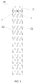
- a covered stent 10 of the present disclosure is of an overall hollow tubular structure, both ends of which are respectively provided with openings.
- the covered stent 10 includes a membrane 12 and a support 11.
- the support 11 includes a plurality of axially arranged waveform rings which are connected by the membrane 12.
- the support 11 also includes a sealing member 14 arranged at the proximal end.
- the sealing member 14 has braiding wires with a smaller diameter, a smaller height and a larger braiding density, so that the sealing member arranged at a proximal end portion can play a better role of sealing the end portion.
- the membrane includes a first membrane 121 and a second membrane 122.
- the support 11 is arranged between the first membrane 121 and the second membrane 122.
- the first membrane 121 is arranged on an inner surface of the covered stent 10, and the first membrane 121 covers an end portion of the support 11.
- the first membrane 121 covers the proximal end of the sealing member 14.
- the second membrane 122 is arranged on an outer surface of the covered stent 10.
- the first membrane can cover only the proximal end of the support, or cover both the proximal end and the distal end of the support.
- the distal end of the membrane will not directly be forward flushed by the blood and is generally not provided with a sealing member, a developing point is also relatively small, and the assembly difficulty is relatively low, so that the present disclosure does not make more restrictions on the layout of the membrane at the distal end of the covered stent.
- the covered stent 10 also includes an anchoring member 15 arranged at the proximal end of the membrane 12.
- the anchoring member 15 is a bare waveform ring, which directly contacts with a vascular tissue after implantation.
- barbs can also be arranged on the anchoring member 15.
- the covered stent 10 also includes an imaging piece 13.
- the imaging piece 13 includes a material with a good imaging characteristic, which can be arranged at the proximal end, distal end and other specific positions to allow imaging of the covered stent.
- the covered stent may not be provided with a sealing and an anchoring member.
- Fig. 2 to Fig. 6 only schematically show positional relationships between the membrane and the support, and the support is only represented by the simplest structure.
- the covered stent 10 of this embodiment includes a first membrane 121, a second membrane 122 and a third membrane 123.
- the proximal end of the second membrane 122 is flush with the proximal end of the support 11; the proximal end portion of the first membrane 121 bypasses the proximal end of the support 11 and covers the proximal end portion of the second membrane 122 to cover the proximal end of the support 11.
- a portion of the first membrane 121 that bypasses the proximal end portion of the support 11 and is then folded towards the second membrane 122 is the third membrane 123. That is, the third membrane 123 and the support 11 sandwich the proximal end portion of the second membrane 122.
- the cross section where the third membrane 123 is located includes three layers of membranes, and two layers of membranes are located on the outer surface of the support 11, and one layer of membrane is located on the inner surface of the support 11.
- the cross section of the covered stent 10 far away from the third membrane 123 only includes at most two layers of membranes.
- no more than three layers of membranes are arranged on the inner and outer surfaces of the support. In this manner, the dimension of the proximal end of the covered stent is reduced, and the overall thickness of the covered stent is also reduced.
- all portions of the same covered stent have a uniform thickness.
- the distance between the distal end of the third membrane 123 and the proximal end of the support 11 is greater than or equal to 15 mm.
- the first membrane 121 first surrounds a mold rod, and the support 11 is then placed. Furthermore, a part with a certain length of the proximal end of the first membrane 121 is not covered by the support 11.
- the second membrane 122 then surrounds the support 11, so that the proximal end of the second membrane 12 is just flush with the proximal end of the support 11, or is slightly beyond the proximal end of the support 11 (considering that a membrane material will be slightly shortened during thermal treatment).
- the portion of the proximal end of the first membrane 121 that is not covered by the support 11 is folded outwardly to cover both the proximal end of the support and the proximal end portion of the second membrane 122.
- the mold rod, the membrane and the support are placed into a thermal treatment equipment together for thermal treatment, so that the first membrane 121 and the second membrane 122 are overall fused to fix the support and also form the third membrane 123.
- the proximal end of the membrane has at most three layers of membranes. Two layers of membranes are located on an outer side of the support, and one layer of membrane is located on an inner side of the support. Furthermore, the second membrane is not folded inward, so that the inner diameter of the proximal end of the covered stent is not affected, and there is no risk that the membrane is flushed away.
- the membrane in the covered stent of the present disclosure, can be fixed by one thermal treatment. The membrane stability is better, and the machining steps are also reduced.
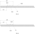
- the covered stent of this embodiment is substantially the same as that of Embodiment I, and a difference lies in the layout of the membrane.
- the covered stent of this embodiment includes a first membrane 221, a second membrane 222 and a third membrane 223.
- the first membrane 221 is arranged on an inner surface of a support 21; a second membrane 222 is arranged on an outer surface of the support 21; and the proximal end of the second membrane 222 is closer to the distal end of the covered stent than a proximal end of the support 21.
- the proximal end portion of the first membrane 221 bypasses the proximal end of the support 21 and is folded towards the second membrane 222 to cover both a proximal end portion of the second membrane 222 and the proximal end of the support 21.
- a portion of the first membrane 221 folded to cover the second membrane 222 is the third membrane 223.
- L1 is preferably greater than an axial length of the sealing member, that is, the distal end of the sealing member is closer to the proximal end of the covered stent than the proximal end of the third membrane 223, so that the third membrane 223 does not cover the sealing member, which reduces the overall dimension of the position where the sealing member is located.
- L2 is preferably greater than or equal to 15 mm.
- the axial length of the sealing member is about 7-8 mm, so the axial length of the third membrane can be 7-8 mm.
- Manufacturing the covered stent of this embodiment is similar to the manufacturing of the covered stent of Embodiment I, except that during covering, the proximal end of the second membrane shall not cover the sealing member, and the proximal end of the second membrane is slightly close to the distal end of the sealing member.
- the subsequent covering process is the same as that in Embodiment I, and will not be repeated here.
- the position where the sealing member is located only includes two layers of membranes, which further reduces the dimension of the proximal end of the covered stent and reduces the difficulty of loading.
- the covered stent of this embodiment includes a first membrane 321, a second membrane 322 and a third membrane 323.
- the first membrane 321 is arranged on an inner surface of a support 31, and the second membrane 322 is arranged on an outer surface of the support 31.
- the first membrane 321 bypasses the proximal end of the support 31 and is folded towards the distal end to form the second membrane 322. That is, the first membrane 321 and the second membrane 322 are of an integrated structure, which is an overall membrane.
- the third membrane 323 is arranged on an outer surface of the second membrane 322, and is close to the proximal end of the support 31.
- the covered stent includes a plurality of sections of third membranes 323, and the plurality of sections of third membranes 323 are axially arranged at intervals around a periphery of the covered stent. Distances between the multiple sections of third membranes can be the same or different. Preferably, the distances between multiple sections of third membranes gradually increase from the proximal end to the distal end.
- the distance between the proximal end of the third membrane 323 at the most proximal end and the proximal end of the support 31 is L3
- the distance between the distal end of the third membrane 323 at the most distal end and the proximal end of the support 31 is L4.
- Preferred ranges of L3 and L4 in this embodiment can refer to the preferred ranges of L1 and L2 in Embodiment II respectively, and will not be repeated here.
- the first membrane 321 first surrounds a mold rod, and the support 31 is then placed. Furthermore, a part with a certain length of the proximal end of the first membrane 321 is not covered by the support 31, and the length of the reserved portion is slightly greater than an axial length of the support. The third membrane then surrounds the proximal end portion of the outer surface of the outward folded first membrane (i.e. the second membrane).
- the distance between the proximal end of the third membrane and the proximal end of the support is controlled at L3, so that more sections of third membranes can be surrounded, but it is required that the distance L4 between the distal end of the third membrane located at the most distal end and the proximal end of the support meets the above requirement.
- the sealing performance between the membrane at the proximal end of the covered stent and a vascular wall can be further improved by means of arranging the multiple sections of third membranes, and the roughness of the outer surface of the covered stent can also be increased, the friction between the outer surface of the covered stent and a blood vessel can be increased, and an anchoring force at the proximal end of the covered stent can be improved.
- the covered stent of this embodiment includes a first membrane 421, a second membrane 422 and a third membrane 423.
- the first membrane 421 is arranged on an inner surface of a support 41; a second membrane 422 is arranged on an outer surface of the support 41; and the proximal end of the second membrane 422 is closer to a distal end of the covered stent than the proximal end of the support 41.
- the covered stent of this embodiment includes a plurality of sections of third membranes 423, and two adjacent sections of the third membranes 423 are stacked end to end.
- the proximal end portion of the first membrane 421 bypasses the proximal end of the support 41 and is folded towards the distal end to form the third membrane 423 located at the most proximal end.
- Other third membranes 423 all include covered portions and uncovered portions, for the convenience of description, which are referred to as "first portion” (or proximal end portion) and "second portion” (or distal end portion).
- the second portion of the third membrane 423 located at the most distal end covers the proximal end portion of the second membrane 422.
- the first portion of the third membrane 423 in the middle is covered by the second portion of the adjacent third membrane 423 at the proximal end.
- the second portion of the third membrane 423 in the middle covers the first portion of the adjacent third membrane 423 at the distal end.
- the second portion of the third membrane close to the proximal end is covered by the first portion of the third membrane close to the distal end.
- the edge of the proximal end of the third membrane is not covered. Therefore, in the early stage of the implantation of the covered stent, the blood is in contact with the edge of the proximal end of the third membrane to speed up endothelialization and improve the anchoring performance of the proximal end of the covered stent.
- the distance between the proximal end of the third membrane 423 at the most proximal end and the proximal end of the support 41 is L5
- the distance between the distal end of the third membrane 423 at the most distal end and the proximal end of the support 41 is L6.
- Preferred ranges of L5 and L6 in this embodiment can refer to the preferred ranges of L1 and L2 in Embodiment II respectively, and will not be repeated here.
- the first membrane 421 first surrounds a mold rod, and the support 41 is then placed. Furthermore, a part with a certain length of the proximal end of the first membrane 421 is not covered by the support 41.
- the second membrane 422 then surrounds the support 41, and the proximal end of the second membrane 422 is far away from the proximal end of the support.
- the proximal end portion of the first membrane 421 is folded outward, ensuring that there is still a part of the support not covered between the proximal end of the first membrane 421 and the proximal end of the second membrane.
- third membrane 423 surrounds the support 41, so that the distal end portion of the third membrane 423 covers the proximal end portion of the second membrane 422, and the proximal end portion of the third membrane 423 is covered by the distal end portion of the first membrane 421.
- a plurality of sections of third membranes 423 surround the support, but it is required that in two adjacent third membranes 423, the distal end portion of the third membrane 423 close to the proximal end covers the proximal end portion of the third membrane 423 close to the distal end.
- the mold rod, the membrane and the support are placed into thermal treatment equipment together for thermal treatment, so that the membranes are overall fused and connected to fix the support.
- a portion of the folded proximal end portion of the first membrane 421 covering the proximal end of the adj acent third membrane also forms the third membrane.
- the covered stent of this embodiment includes multiple sections of third membranes stacked end to end, so that the sealing performance of the proximal end of the covered stent can be further improved. Meanwhile, the roughness of the outer surface of the covered stent can also be increased, the friction between the outer surface of the covered stent and a blood vessel can be increased, and an anchoring force at the proximal end of the covered stent can be improved. In addition, the proximal ends of the third membranes are covered, it is more convenient for loading, and there is no risk that an edge of a membrane is upwarped.
- the covered stent of this embodiment includes a first membrane 521, a second membrane 522 and a third membrane 523.
- the first membrane 521 is arranged on an inner surface of a support 51
- the second membrane 522 is arranged on an outer surface of the support 51.
- the first membrane 521 bypasses the proximal end of the support 51 and is folded towards the distal end to form the second membrane 522. That is, the first membrane 521 and the second membrane 522 are of an integrated structure, which is an overall membrane.
- the third membrane 523 is arranged on an inner surface of the second membrane 522, and is close to the proximal end of the support 51.
- the covered stent includes a plurality of sections of third membranes 523, and the plurality of sections of third membranes 523 are axially arranged at intervals around a periphery of the covered stent.
- the distance between the proximal end of the third membrane 523 at the most proximal end and the proximal end of the support 51 is L7
- the distance between the distal end of the third membrane 523 at the most distal end and the proximal end of the support 51 is L8.
- Preferred ranges of L7 and L8 in this embodiment can refer to the preferred ranges of L1 and L2 in Embodiment II respectively, and will not be repeated here.
- the method of manufacturing the covered stent of this embodiment is similar to the method of manufacturing the covered stent of Embodiment III, but a difference is that after the first membrane and the support surrounds the mold rod, the third membrane surrounds the outer side of a portion which close to the proximal end of the support; and the first membrane is then folded. Other operation steps will be omitted.
- the sealing performance between the membrane at the proximal end of the covered stent and a vascular wall can be further improved by means of arranging the multiple sections of third membranes, and the roughness of the outer surface of the covered stent can also be increased, the friction between the outer surface of the covered stent and a blood vessel can be increased, and an anchoring force at the proximal end of the covered stent can be improved.
- the third membrane is arranged between the second membrane and the support, so that the outer surface of the second membrane is naturally transitioned, which can avoid the risk of an edge of the membrane is scraped off during assembling and releasing of the covered stent.
Landscapes
- Health & Medical Sciences (AREA)
- Engineering & Computer Science (AREA)
- Biomedical Technology (AREA)
- Cardiology (AREA)
- Oral & Maxillofacial Surgery (AREA)
- Transplantation (AREA)
- Heart & Thoracic Surgery (AREA)
- Vascular Medicine (AREA)
- Life Sciences & Earth Sciences (AREA)
- Animal Behavior & Ethology (AREA)
- General Health & Medical Sciences (AREA)
- Public Health (AREA)
- Veterinary Medicine (AREA)
- Gastroenterology & Hepatology (AREA)
- Pulmonology (AREA)
- Prostheses (AREA)
- Media Introduction/Drainage Providing Device (AREA)
Applications Claiming Priority (2)
| Application Number | Priority Date | Filing Date | Title |
|---|---|---|---|
| CN202011507209.9A CN114642526B (zh) | 2020-12-18 | 2020-12-18 | 覆膜支架 |
| PCT/CN2021/125235 WO2022127358A1 (fr) | 2020-12-18 | 2021-10-21 | Endoprothèse recouverte |
Publications (2)
| Publication Number | Publication Date |
|---|---|
| EP4265228A1 true EP4265228A1 (fr) | 2023-10-25 |
| EP4265228A4 EP4265228A4 (fr) | 2024-11-20 |
Family
ID=81991455
Family Applications (1)
| Application Number | Title | Priority Date | Filing Date |
|---|---|---|---|
| EP21905287.5A Pending EP4265228A4 (fr) | 2020-12-18 | 2021-10-21 | Endoprothèse recouverte |
Country Status (4)
| Country | Link |
|---|---|
| US (1) | US20240307201A1 (fr) |
| EP (1) | EP4265228A4 (fr) |
| CN (1) | CN114642526B (fr) |
| WO (1) | WO2022127358A1 (fr) |
Families Citing this family (1)
| Publication number | Priority date | Publication date | Assignee | Title |
|---|---|---|---|---|
| WO2023125434A1 (fr) * | 2021-12-31 | 2023-07-06 | 元心科技(深圳)有限公司 | Système d'endoprothèse couverte et son procédé de préparation |
Family Cites Families (11)
| Publication number | Priority date | Publication date | Assignee | Title |
|---|---|---|---|---|
| US6488701B1 (en) * | 1998-03-31 | 2002-12-03 | Medtronic Ave, Inc. | Stent-graft assembly with thin-walled graft component and method of manufacture |
| US6808533B1 (en) * | 2000-07-28 | 2004-10-26 | Atrium Medical Corporation | Covered stent and method of covering a stent |
| JP2004508084A (ja) * | 2000-09-05 | 2004-03-18 | メデバート リミティド | 体腔ライナー |
| GB2449784B8 (en) * | 2004-02-09 | 2009-04-29 | Cook Biotech Inc | Stent graft devices having collagen coating. |
| GB0517085D0 (en) * | 2005-08-19 | 2005-09-28 | Angiomed Ag | Polymer prosthesis |
| US8221486B2 (en) * | 2006-11-21 | 2012-07-17 | Boston Scientific Scimed, Inc. | Laminated stent graft edge binding |
| CN101627933B (zh) * | 2008-07-17 | 2012-10-17 | 微创医疗器械(上海)有限公司 | 覆膜支架 |
| CN104027152A (zh) * | 2013-03-07 | 2014-09-10 | 上海微创医疗器械(集团)有限公司 | 一种新型双层覆膜支架 |
| WO2014148122A1 (fr) * | 2013-03-18 | 2014-09-25 | 株式会社パイオラックスメディカルデバイス | Endoprothèse |
| CN112451170B (zh) * | 2016-12-28 | 2022-09-02 | 先健科技(深圳)有限公司 | 覆膜支架 |
| JP2021502867A (ja) * | 2017-08-17 | 2021-02-04 | エーエスピーアイピー・インクAspip Inc. | 眼内圧上昇の治療方法、治療装置、および治療システム |
-
2020
- 2020-12-18 CN CN202011507209.9A patent/CN114642526B/zh active Active
-
2021
- 2021-10-21 US US18/268,132 patent/US20240307201A1/en active Pending
- 2021-10-21 WO PCT/CN2021/125235 patent/WO2022127358A1/fr not_active Ceased
- 2021-10-21 EP EP21905287.5A patent/EP4265228A4/fr active Pending
Also Published As
| Publication number | Publication date |
|---|---|
| CN114642526B (zh) | 2026-03-31 |
| US20240307201A1 (en) | 2024-09-19 |
| EP4265228A4 (fr) | 2024-11-20 |
| CN114642526A (zh) | 2022-06-21 |
| WO2022127358A1 (fr) | 2022-06-23 |
Similar Documents
| Publication | Publication Date | Title |
|---|---|---|
| US20230218416A1 (en) | Apparatus and method of placement of a graft or graft system | |
| EP3090707B1 (fr) | Endoprothèse peropératoire d'arc de l'aorte et son procédé de fabrication | |
| US8828074B2 (en) | Stent graft having short tube graft for branch vessel | |
| EP3494934B1 (fr) | Stent avec bras de positionnement | |
| WO2019042202A1 (fr) | Stent recouvert | |
| WO2025051268A1 (fr) | Endoprothèse couverte, système d'endoprothèse et utilisation | |
| CN105979913A (zh) | 可变陷支架(vds)和波浪形接枝组件 | |
| CN109419566A (zh) | 覆膜支架 | |
| WO2015188775A1 (fr) | Collet anévrismal artificiel et son procédé de fabrication | |
| CN105559945A (zh) | 覆膜支架及其制造方法 | |
| EP4265228A1 (fr) | Endoprothèse recouverte | |
| WO2022007560A1 (fr) | Stent recouvert | |
| CN118058873B (zh) | 血管腔内修复平行支架 | |
| CN217338975U (zh) | 一种覆膜支架及支架组件 | |
| US20050273154A1 (en) | Bifurcated stent graft and apparatus for making same | |
| CN113893062B (zh) | 覆膜支架 | |
| CN108236511A (zh) | 支架系统及其制备方法 | |
| US20240325183A1 (en) | Stent graft delivery method | |
| CN206934210U (zh) | 覆膜支架及输送系统 | |
| CN211271435U (zh) | 升主动脉及主动脉弓部变波幅预弯支架 | |
| EP4473948A2 (fr) | Système de pose de greffe d'endoprothèse à embout conique décalé | |
| CN110638562A (zh) | 升主动脉及主动脉弓部变波幅预弯支架 | |
| JP7721226B2 (ja) | ステントグラフト、ステントグラフトの展開方法 | |
| CN115884733B (zh) | 制备高柔性支架移植物的方法和支架移植物 | |
| CN120203856A (zh) | 覆膜支架 |
Legal Events
| Date | Code | Title | Description |
|---|---|---|---|
| STAA | Information on the status of an ep patent application or granted ep patent |
Free format text: STATUS: THE INTERNATIONAL PUBLICATION HAS BEEN MADE |
|
| PUAI | Public reference made under article 153(3) epc to a published international application that has entered the european phase |
Free format text: ORIGINAL CODE: 0009012 |
|
| STAA | Information on the status of an ep patent application or granted ep patent |
Free format text: STATUS: REQUEST FOR EXAMINATION WAS MADE |
|
| 17P | Request for examination filed |
Effective date: 20230717 |
|
| AK | Designated contracting states |
Kind code of ref document: A1 Designated state(s): AL AT BE BG CH CY CZ DE DK EE ES FI FR GB GR HR HU IE IS IT LI LT LU LV MC MK MT NL NO PL PT RO RS SE SI SK SM TR |
|
| DAV | Request for validation of the european patent (deleted) | ||
| DAX | Request for extension of the european patent (deleted) | ||
| A4 | Supplementary search report drawn up and despatched |
Effective date: 20241017 |
|
| RIC1 | Information provided on ipc code assigned before grant |
Ipc: A61F 2/90 20130101AFI20241011BHEP |