EP4265341A1 - Beschichtungsvorrichtung und beschichtungsverfahren - Google Patents
Beschichtungsvorrichtung und beschichtungsverfahren Download PDFInfo
- Publication number
- EP4265341A1 EP4265341A1 EP22712488.0A EP22712488A EP4265341A1 EP 4265341 A1 EP4265341 A1 EP 4265341A1 EP 22712488 A EP22712488 A EP 22712488A EP 4265341 A1 EP4265341 A1 EP 4265341A1
- Authority
- EP
- European Patent Office
- Prior art keywords
- slurry
- slot
- die
- piece
- coating
- Prior art date
- Legal status (The legal status is an assumption and is not a legal conclusion. Google has not performed a legal analysis and makes no representation as to the accuracy of the status listed.)
- Granted
Links
Images




Classifications
-
- B—PERFORMING OPERATIONS; TRANSPORTING
- B05—SPRAYING OR ATOMISING IN GENERAL; APPLYING FLUENT MATERIALS TO SURFACES, IN GENERAL
- B05C—APPARATUS FOR APPLYING FLUENT MATERIALS TO SURFACES, IN GENERAL
- B05C5/00—Apparatus in which liquid or other fluent material is projected, poured or allowed to flow on to the surface of the work
- B05C5/02—Apparatus in which liquid or other fluent material is projected, poured or allowed to flow on to the surface of the work the liquid or other fluent material being discharged through an outlet orifice by pressure, e.g. from an outlet device in contact or almost in contact, with the work
-
- B—PERFORMING OPERATIONS; TRANSPORTING
- B05—SPRAYING OR ATOMISING IN GENERAL; APPLYING FLUENT MATERIALS TO SURFACES, IN GENERAL
- B05C—APPARATUS FOR APPLYING FLUENT MATERIALS TO SURFACES, IN GENERAL
- B05C5/00—Apparatus in which liquid or other fluent material is projected, poured or allowed to flow on to the surface of the work
- B05C5/02—Apparatus in which liquid or other fluent material is projected, poured or allowed to flow on to the surface of the work the liquid or other fluent material being discharged through an outlet orifice by pressure, e.g. from an outlet device in contact or almost in contact, with the work
- B05C5/0254—Coating heads with slot-shaped outlet
- B05C5/0258—Coating heads with slot-shaped outlet flow controlled, e.g. by a valve
-
- B—PERFORMING OPERATIONS; TRANSPORTING
- B05—SPRAYING OR ATOMISING IN GENERAL; APPLYING FLUENT MATERIALS TO SURFACES, IN GENERAL
- B05C—APPARATUS FOR APPLYING FLUENT MATERIALS TO SURFACES, IN GENERAL
- B05C5/00—Apparatus in which liquid or other fluent material is projected, poured or allowed to flow on to the surface of the work
- B05C5/02—Apparatus in which liquid or other fluent material is projected, poured or allowed to flow on to the surface of the work the liquid or other fluent material being discharged through an outlet orifice by pressure, e.g. from an outlet device in contact or almost in contact, with the work
- B05C5/0254—Coating heads with slot-shaped outlet
- B05C5/0262—Coating heads with slot-shaped outlet adjustable in width, i.e. having lips movable relative to each other in order to modify the slot width, e.g. to close it
-
- B—PERFORMING OPERATIONS; TRANSPORTING
- B05—SPRAYING OR ATOMISING IN GENERAL; APPLYING FLUENT MATERIALS TO SURFACES, IN GENERAL
- B05C—APPARATUS FOR APPLYING FLUENT MATERIALS TO SURFACES, IN GENERAL
- B05C11/00—Component parts, details or accessories not specifically provided for in groups B05C1/00 - B05C9/00
- B05C11/10—Storage, supply or control of liquid or other fluent material; Recovery of excess liquid or other fluent material
- B05C11/1002—Means for controlling supply, i.e. flow or pressure, of liquid or other fluent material to the applying apparatus, e.g. valves
- B05C11/1005—Means for controlling supply, i.e. flow or pressure, of liquid or other fluent material to the applying apparatus, e.g. valves responsive to condition of liquid or other fluent material already applied to the surface, e.g. coating thickness, weight or pattern
-
- H—ELECTRICITY
- H01—ELECTRIC ELEMENTS
- H01M—PROCESSES OR MEANS, e.g. BATTERIES, FOR THE DIRECT CONVERSION OF CHEMICAL ENERGY INTO ELECTRICAL ENERGY
- H01M10/00—Secondary cells; Manufacture thereof
- H01M10/05—Accumulators with non-aqueous electrolyte
- H01M10/052—Li-accumulators
-
- H—ELECTRICITY
- H01—ELECTRIC ELEMENTS
- H01M—PROCESSES OR MEANS, e.g. BATTERIES, FOR THE DIRECT CONVERSION OF CHEMICAL ENERGY INTO ELECTRICAL ENERGY
- H01M4/00—Electrodes
- H01M4/02—Electrodes composed of, or comprising, active material
- H01M4/04—Processes of manufacture in general
-
- H—ELECTRICITY
- H01—ELECTRIC ELEMENTS
- H01M—PROCESSES OR MEANS, e.g. BATTERIES, FOR THE DIRECT CONVERSION OF CHEMICAL ENERGY INTO ELECTRICAL ENERGY
- H01M4/00—Electrodes
- H01M4/02—Electrodes composed of, or comprising, active material
- H01M4/04—Processes of manufacture in general
- H01M4/0402—Methods of deposition of the material
- H01M4/0404—Methods of deposition of the material by coating on electrode collectors
-
- H—ELECTRICITY
- H01—ELECTRIC ELEMENTS
- H01M—PROCESSES OR MEANS, e.g. BATTERIES, FOR THE DIRECT CONVERSION OF CHEMICAL ENERGY INTO ELECTRICAL ENERGY
- H01M4/00—Electrodes
- H01M4/02—Electrodes composed of, or comprising, active material
- H01M4/04—Processes of manufacture in general
- H01M4/0402—Methods of deposition of the material
- H01M4/0411—Methods of deposition of the material by extrusion
-
- H—ELECTRICITY
- H01—ELECTRIC ELEMENTS
- H01M—PROCESSES OR MEANS, e.g. BATTERIES, FOR THE DIRECT CONVERSION OF CHEMICAL ENERGY INTO ELECTRICAL ENERGY
- H01M4/00—Electrodes
- H01M4/02—Electrodes composed of, or comprising, active material
- H01M4/13—Electrodes for accumulators with non-aqueous electrolyte, e.g. for lithium-accumulators; Processes of manufacture thereof
- H01M4/139—Processes of manufacture
-
- Y—GENERAL TAGGING OF NEW TECHNOLOGICAL DEVELOPMENTS; GENERAL TAGGING OF CROSS-SECTIONAL TECHNOLOGIES SPANNING OVER SEVERAL SECTIONS OF THE IPC; TECHNICAL SUBJECTS COVERED BY FORMER USPC CROSS-REFERENCE ART COLLECTIONS [XRACs] AND DIGESTS
- Y02—TECHNOLOGIES OR APPLICATIONS FOR MITIGATION OR ADAPTATION AGAINST CLIMATE CHANGE
- Y02E—REDUCTION OF GREENHOUSE GAS [GHG] EMISSIONS, RELATED TO ENERGY GENERATION, TRANSMISSION OR DISTRIBUTION
- Y02E60/00—Enabling technologies; Technologies with a potential or indirect contribution to GHG emissions mitigation
- Y02E60/10—Energy storage using batteries
Definitions
- the present application relates to the technical field of battery electrode piece coating, in particular to coating equipment and a coating method.
- lithium ion batteries Due to the advantages of high specific capacity, high working voltage, no environmental pollution, long cycle life, wide working temperature range and the like, lithium ion batteries are widely applied to electronic products such as mobile phones, notebook computers and digital cameras, and automobiles. With the rapid development of science and economy, the requirements on the performance of the lithium ion batteries are getting higher and higher.
- a double-layer coating die in the lithium battery industry is mainly adjusted manually, and the adjustment method has higher requirements on skills of debugging personnel, resulting in poor debugging effectiveness and low efficiency.
- coating equipment comprising:
- the coating equipment further comprises an upper die, a middle die and a lower die, wherein the upper die and the middle die define the first slot, and the lower die and the middle die define the second slot; the first adjusting mechanism is arranged on the upper die and/or the middle die, and the second adjusting mechanism is arranged on the lower die and/or the middle die.
- the coating equipment further comprises:
- the upper die and the lower die jointly define a die lip for slurry to flow out;
- the middle die comprises a first slurry-feeding port, one end of the first slurry-feeding port is configured to be connected with a first slurry-supply system, and the other end of the first slurry-feeding port communicates with the first slot;
- the lower die comprises a second slurry-feeding port, one end of the second slurry-feeding port is configured to be connected with a second slurry-supply system, and the other end of the second slurry-feeding port communicates with the second slot.
- the slurry parameter detector is a thickness detector, and the thickness detector is configured to detect the thickness of slurry on the electrode piece; and/or the slurry parameter detector is a surface density detector, and the surface density detector is configured to detect the surface density of slurry on the electrode piece.
- any one of the adjusting mechanisms further comprises a driving board, wherein the driving board is in communication connection with the corresponding driving piece, and the driving board is in communication connection with the slurry parameter detector; the driving piece is configured to drive the corresponding adjusting piece to move under the driving of the driving board so as to adjust the flow rate of slurry in the corresponding slot.
- the coating equipment further comprises a bus socket that is arranged on at least one side of the adjusting mechanism, and the bus socket is in communication connection with the driving board.
- the coating equipment further comprises a glue dispensing mechanism which comprises a glue dispensing valve and a first glue dispensing channel, wherein the glue dispensing valve is mounted on the upper die, the first glue dispensing channel is arranged in the upper die, and the first glue dispensing channel communicates with the first slot and the glue dispensing valve;
- the glue dispensing mechanism further comprises a second glue dispensing channel, wherein the second glue dispensing channel is arranged in the middle die, and the first slot communicates with the second slot through the second glue dispensing channel.
- the present application discloses a coating method, comprising:
- the coating method further comprises:
- the coating method adopts the coating equipment.
- the technical solution provided by the present application has the following advantages: in the coating equipment provided by the present application, by arranging the first adjusting mechanism and the second adjusting mechanism, adjustment of the flow rate of the slurry circulating in the first slot and the second slot can be realized, and moreover, the parameters of the coated slurry are detected by the slurry parameter detector, and are then compared with preset values, and comparison results are fed back to the first adjusting mechanism and the second adjusting mechanism for adjustment of the first adjusting piece and the second adjusting piece, so that automatic adjustment of double-layer die coating is realized, the debugging effectiveness is greatly improved, and the coating efficiency is further improved.
- connection can be fixed connection, or detachable connection, or integrated connection, can be mechanical connection, and can also be electrical connection, and can be direct connection, can also be indirect connection through an intermediate medium, and can be internal communication between two elements.
- connection can be fixed connection, or detachable connection, or integrated connection, can be mechanical connection, and can also be electrical connection, and can be direct connection, can also be indirect connection through an intermediate medium, and can be internal communication between two elements.
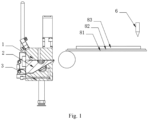
- the coating equipment comprises a coating die and a slurry parameter detector 6.
- the coating die comprises an upper die 1, a middle die 2, a lower die 3, a first adjusting mechanism 4 and a second adjusting mechanism 5.
- the upper die 1 and the middle die 2 form a first slot 71 configured for circulation of first slurry
- the lower die 3 and the middle die 2 form a second slot 72 configured for circulation of second slurry
- an intersection angle is formed between the first slot 71 and the second slot 72
- the first adjusting mechanism 4 is arranged on the upper die 1 and comprises a first driving piece 41 and a first adjusting piece 42, and a driving end of the first driving piece 41 is connected with the first adjusting piece 42
- the second adjusting mechanism 5 is arranged on the lower die 3 and comprises a second driving piece 51 and a second adjusting piece 52, and a driving end of the second driving piece 51 is connected with the second adjusting piece 52
- the slurry parameter detector 6 is in communication connection with the first adjusting mechanism 4 and the second adjusting mechanism 5 and is configured to detect information of slurry on an electrode piece 81.
- the slurry parameter detector 6 is configured to detect slurry information of the first slurry coated on the electrode piece 81 via the first slot 71 and forms a first slurry parameter
- the first adjusting mechanism 4 is configured to adjust the position of the first adjusting piece 42 according to the first slurry parameter so as to adjust the flow rate of the first slurry circulating in the first slot 71
- the slurry parameter detector 6 is further configured to detect slurry information of the second slurry coated on the electrode piece 81 via the second slot 72 and forms a second slurry parameter
- the second adjusting mechanism 5 is configured to adjust the position of the second adjusting piece 52 according to the second slurry parameter so as to adjust the flow rate of the second slurry circulating in the second slot 72.
- the coating equipment provided by this embodiment, by arranging the first adjusting mechanism 4 and the second adjusting mechanism 5, adjustment of the flow rate of the slurry circulating in the first slot 71 and the second slot 72 can be realized, and moreover, the parameters of the coated slurry are detected by the slurry parameter detector 6, and are then compared with preset values, and comparison results are fed back to the first adjusting mechanism 4 and the second adjusting mechanism 5 for adjustment of the first adjusting piece 42 and the second adjusting piece 52, so that automatic adjustment of double-layer die coating is realized, the debugging effectiveness is greatly improved, and the coating efficiency is further improved.
- the coating equipment provided by this embodiment further comprises a first gasket and a second gasket.
- first gasket is arranged between the upper die 1 and the middle die 2, so that the first gasket, the upper die 1 and the middle die 2 jointly define the first slot 71;
- second gasket is arranged between the middle die 2 and the lower die 3, so that the second gasket, the middle die 2 and the lower die 3 jointly define the second slot 72.
- the first slot 71 is horizontally arranged, and the second slot 72 is obliquely arranged upwards in the flowing direction of the second slurry.
- the first slot 71 extends in the horizontal direction, and the second slot 72 is arranged at an inclination angle of 30 degrees relative to the first slot 71.
- the inclination angle of the second slot 72 can be 45 degrees, 20 degrees and the like.
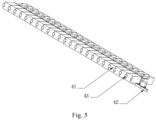
- the first adjusting mechanism 4 further comprises a first driving board 43, the first driving board 43 is in communication connection with the first driving piece 41, and the first driving board 43 is in communication connection with the slurry parameter detector 6; the first driving piece 41 is configured to adjust the position, extending into the first slot 71, of the first adjusting piece 42 under the driving of the first driving board 43 so as to adjust the flow rate of the first slurry in the first slot 71.
- the first driving piece 41 is one or more of a stepping motor, an ultrasonic motor and a piezoelectric motor.
- the first adjusting piece 42 is a T-shaped block.
- the T-shaped block comprises a rod part and an intercepting part in the shape of a rectangular block, the intercepting part is arranged on a side close to the first slot 71, and when the intercepting part extends into the first slot 71, interception of the circulating process of the first slurry can be realized, and then the flow rate of the first slurry is adjusted.
- the upper die 1 and the lower die 3 jointly define a die lip for slurry to flow out;
- the lower die 3 comprises a deformation part 33 and a base part 32, the deformation part 33 is arranged on a side close to the die lip, and the base part 32 is arranged on a side away from the die lip;
- the second driving piece 51 is mounted on the base part 32, and the second adjusting piece 52 is connected with the deformation part 33;
- the second adjusting piece 52 has a die lip adjusting state of driving the deformation part 33 to move towards or away from the base part 32 under the action of the second driving piece 51, and in the die lip adjusting state, a lower lip of the lower die 3 is warped relative to an upper lip of the upper die 1.
- the second driving piece 51 is one or more of a stepping motor, an ultrasonic motor and a piezoelectric motor.
- the second adjusting piece is a connecting rod, one end of the connecting rod is connected with the output end of the motor, the other end of the connecting rod is connected with the deformation part 33, and therefore deformation of the deformation part is realized under the driving of the motor.
- the second adjusting piece 52 comprises a push rod and a pull rod, and when in use, the deformation part is pushed by the push rod to move away from the base part, or the deformation part is pulled by the pull rod to move towards the base part.
- the push rod abuts against the side wall face of the deformation part, when the second driving piece drives a rigid screw to rotate, the push rod can push the deformation part to move, then the distance between the base part 32 and the deformation part 33 is adjusted, and then the lower lip of the lower die 3 is slightly deformed.
- the pull rod is in threaded connection with the deformation part, and when the second driving piece drives the pull rod to move, the pull rod can pull the deformation part to move towards the base part.
- the second adjusting mechanism 5 further comprises a second driving board, the second driving board is in communication connection with the second driving piece 51, and the second driving board is in communication connection with the slurry parameter detector 6; the second driving piece 51 is configured to adjust the relative position between the base part 32 and the deformation part 33 under the driving of the second driving board so as to adjust the flow rate of the second slurry flowing out of the second slot 72.
- the middle die 2 comprises a first slurry-feeding port 21, one end of the first slurry-feeding port 21 is configured to be connected with a first slurry-supply system, and the other end of the first slurry-feeding port 21 communicates with the first slot 71;
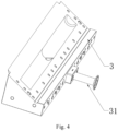
- the lower die 3 comprises a second slurry-feeding port 31, one end of the second slurry-feeding port 31 is configured to be connected with a second slurry-supply system, and the other end of the second slurry-feeding port 31 communicates with the second slot 72.
- the second slurry-feeding port 31 is formed in the bottom face of the lower die 3, and by the adoption of such arrangement of the second slurry-feeding port 31, the cutting amount of the lower die 3 is small, the production period is short, and the production process is simple.
- the second slurry-feeding port 31 can also be formed in the back side of the lower die 3.
- the slurry parameter detector 6 is a thickness detector, and the thickness detector is configured to detect the thickness of slurry on the electrode piece 81;
- the thickness detector is a thickness detection instrument, specifically, an ⁇ -ray or ⁇ -ray type NDC measuring probe can be used, the mass of unit area can be measured, and then the coating thickness can be obtained;
- the slurry parameter detector 6 can also be a surface density detector, the surface density detector is configured to detect the surface density of slurry on the electrode piece 81, and the surface density detector can be a densimeter.
- the thickness detector and the surface density detector can also be used at the same time.
- the coating equipment provided by this embodiment further comprises a bus socket, and the bus socket is arranged at the two ends of the adjusting mechanism and is in communication connection with the driving board. Tabs at the two ends of the driving board are inserted into the bus socket, and due to the arrangement of the bus socket, power is provided for the adjusting mechanisms, and communication connection is realized for the multiple driving boards and the multiple adjusting mechanisms.
- the coating equipment provided by this embodiment further comprises a glue dispensing mechanism
- the glue dispensing mechanism comprises a glue dispensing valve 91 arranged on the upper die 1 and a first glue dispensing channel 92 arranged in the upper die.
- the glue dispensing channel 92 communicates with the glue dispensing valve 91, and the first glue dispensing channel 92 communicates with a glue flowing channel in the first gasket, so that upper-layer glue dispensing is realized.
- a communicating hole can be formed in the first gasket
- the glue dispensing mechanism further comprises a second glue dispensing channel 93 arranged in the middle die 2, the second glue dispensing channel communicates with the first glue dispensing channel 92 through the communicating hole, and the side, away from the first gasket, of the second glue dispensing channel 93 communicates with a glue flowing channel in the second gasket, and then lower-layer glue dispensing is realized.
- the set positions of the first adjusting mechanism and the second adjusting mechanism can be changed, for example, the first adjusting mechanism can be arranged on the middle die, and the second adjusting mechanism can also be arranged on the middle die as long as the first adjusting mechanism can change the flow rate of the first slurry in the first slot and the second adjusting mechanism can change the flow rate of the second slurry in the second slot.
- This embodiment provides a coating method, as shown in Fig. 7 , which comprises the following steps:
- This embodiment provides a coating method, and the specific coating method is the coating method provided in embodiment 2 and adopts the coating equipment provided in embodiment 1.
Landscapes
- Engineering & Computer Science (AREA)
- Chemical & Material Sciences (AREA)
- Manufacturing & Machinery (AREA)
- Chemical Kinetics & Catalysis (AREA)
- Electrochemistry (AREA)
- General Chemical & Material Sciences (AREA)
- Materials Engineering (AREA)
- Coating Apparatus (AREA)
- Application Of Or Painting With Fluid Materials (AREA)
Applications Claiming Priority (1)
| Application Number | Priority Date | Filing Date | Title |
|---|---|---|---|
| PCT/CN2022/077755 WO2023159438A1 (zh) | 2022-02-24 | 2022-02-24 | 一种涂布设备及涂布方法 |
Publications (3)
| Publication Number | Publication Date |
|---|---|
| EP4265341A1 true EP4265341A1 (de) | 2023-10-25 |
| EP4265341A4 EP4265341A4 (de) | 2023-10-25 |
| EP4265341B1 EP4265341B1 (de) | 2025-08-27 |
Family
ID=82232959
Family Applications (1)
| Application Number | Title | Priority Date | Filing Date |
|---|---|---|---|
| EP22712488.0A Active EP4265341B1 (de) | 2022-02-24 | 2022-02-24 | Beschichtungsvorrichtung und beschichtungsverfahren |
Country Status (6)
| Country | Link |
|---|---|
| US (1) | US12330185B2 (de) |
| EP (1) | EP4265341B1 (de) |
| JP (1) | JP7640817B1 (de) |
| KR (1) | KR102830800B1 (de) |
| CN (1) | CN114728303B (de) |
| WO (1) | WO2023159438A1 (de) |
Families Citing this family (5)
| Publication number | Priority date | Publication date | Assignee | Title |
|---|---|---|---|---|
| CN115846140A (zh) * | 2022-12-21 | 2023-03-28 | 深圳市曼恩斯特科技股份有限公司 | 一种涂布模头闭环调节装置 |
| CN115970987B (zh) * | 2023-02-15 | 2023-10-31 | 重庆太蓝新能源有限公司 | 挤压涂布模头和涂布机 |
| CN116371674A (zh) * | 2023-03-17 | 2023-07-04 | 上川精密科技(无锡)有限公司 | 一种用于锂电池双层涂布模头下层涂布面密度的调节结构 |
| CN219898877U (zh) * | 2023-07-27 | 2023-10-27 | 宁德时代新能源科技股份有限公司 | 一种涂布装置及电池加工设备 |
| CN116748081B (zh) * | 2023-08-18 | 2024-01-12 | 宁德时代新能源科技股份有限公司 | 涂布系统及方法 |
Family Cites Families (17)
| Publication number | Priority date | Publication date | Assignee | Title |
|---|---|---|---|---|
| JPH07204561A (ja) * | 1994-01-19 | 1995-08-08 | Mitsubishi Heavy Ind Ltd | スリットノズル塗装装置 |
| JP2000334359A (ja) * | 1999-05-26 | 2000-12-05 | Sony Corp | 塗布方法及びその装置 |
| JP4560975B2 (ja) | 2001-03-27 | 2010-10-13 | 株式会社Ihi | カーテンコータヘッドの塗工液吐出流量計測装置及び該計測装置を用いた塗工液吐出流量調整装置 |
| JP5522025B2 (ja) | 2010-12-27 | 2014-06-18 | トヨタ自動車株式会社 | 塗工装置、塗工方法、電池の製造方法 |
| CN109550642B (zh) * | 2017-09-26 | 2023-10-13 | 东莞市雅康精密机械有限公司 | 锂离子电池极片的涂布模头和涂布机 |
| CN208810447U (zh) | 2018-07-26 | 2019-05-03 | 浙江精诚模具机械有限公司 | 一种带微分流量调节结构的涂覆模头 |
| CN109225763B (zh) * | 2018-10-30 | 2024-05-03 | 深圳市曼恩斯特科技股份有限公司 | 涂布头、涂布装置及涂布方法 |
| CN109513570B (zh) * | 2018-10-30 | 2022-08-19 | 深圳市曼恩斯特科技股份有限公司 | 涂布头、涂布装置及涂布方法 |
| CN209772575U (zh) | 2018-12-05 | 2019-12-13 | 深圳市曼恩斯特科技有限公司 | 狭缝涂布头 |
| KR102685121B1 (ko) * | 2019-03-28 | 2024-07-12 | 주식회사 엘지에너지솔루션 | 듀얼 슬롯 다이 코터 |
| CN110252593A (zh) * | 2019-06-17 | 2019-09-20 | 深圳市曼恩斯特科技有限公司 | 涂布机及其涂布方法 |
| KR102239354B1 (ko) | 2019-10-14 | 2021-04-13 | 황은보 | 다이 립의 갭 조정 및 유지가 가능한 코팅 장치 및 이를 포함하는 코팅 시스템 |
| CN115210003B (zh) | 2020-08-03 | 2024-07-02 | 株式会社Lg新能源 | 多狭缝模具涂布机 |
| CN212820842U (zh) * | 2020-09-18 | 2021-03-30 | 宁德中能电子设备有限公司 | 电池极片涂布的涂布模头 |
| CN214320738U (zh) | 2020-12-17 | 2021-10-01 | 宁德中能电子设备有限公司 | 电池极片自动涂布装置 |
| CN214390896U (zh) * | 2021-01-22 | 2021-10-15 | 宁德时代新能源科技股份有限公司 | 一种涂布系统 |
| CN112871579A (zh) * | 2021-03-23 | 2021-06-01 | 深圳市曼恩斯特科技股份有限公司 | 一种双层涂布模头及涂布机 |
-
2022
- 2022-02-24 US US18/840,798 patent/US12330185B2/en active Active
- 2022-02-24 JP JP2024550791A patent/JP7640817B1/ja active Active
- 2022-02-24 CN CN202280000441.4A patent/CN114728303B/zh active Active
- 2022-02-24 WO PCT/CN2022/077755 patent/WO2023159438A1/zh not_active Ceased
- 2022-02-24 KR KR1020247031218A patent/KR102830800B1/ko active Active
- 2022-02-24 EP EP22712488.0A patent/EP4265341B1/de active Active
Also Published As
| Publication number | Publication date |
|---|---|
| EP4265341B1 (de) | 2025-08-27 |
| US12330185B2 (en) | 2025-06-17 |
| WO2023159438A1 (zh) | 2023-08-31 |
| KR102830800B1 (ko) | 2025-07-07 |
| US20250108402A1 (en) | 2025-04-03 |
| JP7640817B1 (ja) | 2025-03-05 |
| EP4265341A4 (de) | 2023-10-25 |
| CN114728303B (zh) | 2024-04-19 |
| WO2023159438A9 (zh) | 2024-08-22 |
| JP2025508897A (ja) | 2025-04-10 |
| KR20240154582A (ko) | 2024-10-25 |
| CN114728303A (zh) | 2022-07-08 |
Similar Documents
| Publication | Publication Date | Title |
|---|---|---|
| EP4265341A1 (de) | Beschichtungsvorrichtung und beschichtungsverfahren | |
| CN112007824A (zh) | 电池极片涂布的涂布模头及其工作方法 | |
| CN116060251A (zh) | 涂布装置、涂布系统以及涂布方法 | |
| CN214830542U (zh) | 一种直缝焊管热处理用可调节加热机构 | |
| US20250276339A1 (en) | Coating apparatus and battery processing device | |
| CN209342206U (zh) | 一种水库水位信息远程计算机监测装置 | |
| CN219424787U (zh) | 涂布模头及涂布装置 | |
| CN108955586A (zh) | 面层平整度激光测量装置 | |
| CN208125789U (zh) | 一种电能计量装置固定支架 | |
| CN117578842A (zh) | 一种小型化集中安装式储能变流器 | |
| CN212585640U (zh) | 一种锂电池极耳间距检测工装 | |
| CN214303386U (zh) | 一种间距可调的冰箱合页 | |
| WO2023015458A1 (zh) | 电池极片涂布装置 | |
| CN220419413U (zh) | 一种用于电芯检测的连接装置 | |
| CN206194913U (zh) | 一种用于锂电池爆破试验的装置 | |
| CN215548214U (zh) | 一种宇航用方形金属壳锂离子蓄电池模块装配工装 | |
| CN218162239U (zh) | 一种水下装置用温差能充电装置 | |
| CN221984384U (zh) | 箱胆组件、插胆工装及插胆设备 | |
| CN221746140U (zh) | 单相物联电能表远程控制装置 | |
| CN212480622U (zh) | 一种三角风机启动专用箱的安装结构 | |
| CN112996315B (zh) | 一种军工电源的反馈控制器 | |
| CN219113280U (zh) | 一种方形电池极耳焊接夹具 | |
| CN222369461U (zh) | 一种双层涂布模头 | |
| CN218394486U (zh) | 一种精准可调节刀片高度的锂电池涂布机 | |
| CN221907992U (zh) | 一种实时检测的狭缝涂布装置 |
Legal Events
| Date | Code | Title | Description |
|---|---|---|---|
| STAA | Information on the status of an ep patent application or granted ep patent |
Free format text: STATUS: UNKNOWN |
|
| STAA | Information on the status of an ep patent application or granted ep patent |
Free format text: STATUS: THE INTERNATIONAL PUBLICATION HAS BEEN MADE |
|
| PUAI | Public reference made under article 153(3) epc to a published international application that has entered the european phase |
Free format text: ORIGINAL CODE: 0009012 |
|
| STAA | Information on the status of an ep patent application or granted ep patent |
Free format text: STATUS: REQUEST FOR EXAMINATION WAS MADE |
|
| 17P | Request for examination filed |
Effective date: 20220405 |
|
| A4 | Supplementary search report drawn up and despatched |
Effective date: 20230809 |
|
| AK | Designated contracting states |
Kind code of ref document: A1 Designated state(s): AL AT BE BG CH CY CZ DE DK EE ES FI FR GB GR HR HU IE IS IT LI LT LU LV MC MK MT NL NO PL PT RO RS SE SI SK SM TR |
|
| STAA | Information on the status of an ep patent application or granted ep patent |
Free format text: STATUS: EXAMINATION IS IN PROGRESS |
|
| 17Q | First examination report despatched |
Effective date: 20240620 |
|
| GRAP | Despatch of communication of intention to grant a patent |
Free format text: ORIGINAL CODE: EPIDOSNIGR1 |
|
| STAA | Information on the status of an ep patent application or granted ep patent |
Free format text: STATUS: GRANT OF PATENT IS INTENDED |
|
| DAV | Request for validation of the european patent (deleted) | ||
| DAX | Request for extension of the european patent (deleted) | ||
| INTG | Intention to grant announced |
Effective date: 20250320 |
|
| GRAS | Grant fee paid |
Free format text: ORIGINAL CODE: EPIDOSNIGR3 |
|
| GRAA | (expected) grant |
Free format text: ORIGINAL CODE: 0009210 |
|
| STAA | Information on the status of an ep patent application or granted ep patent |
Free format text: STATUS: THE PATENT HAS BEEN GRANTED |
|
| AK | Designated contracting states |
Kind code of ref document: B1 Designated state(s): AL AT BE BG CH CY CZ DE DK EE ES FI FR GB GR HR HU IE IS IT LI LT LU LV MC MK MT NL NO PL PT RO RS SE SI SK SM TR |
|
| REG | Reference to a national code |
Ref country code: CH Ref legal event code: EP |
|
| REG | Reference to a national code |
Ref country code: DE Ref legal event code: R096 Ref document number: 602022020213 Country of ref document: DE |
|
| REG | Reference to a national code |
Ref country code: IE Ref legal event code: FG4D |
|
| REG | Reference to a national code |
Ref country code: NL Ref legal event code: MP Effective date: 20250827 |
|
| PG25 | Lapsed in a contracting state [announced via postgrant information from national office to epo] |
Ref country code: IS Free format text: LAPSE BECAUSE OF FAILURE TO SUBMIT A TRANSLATION OF THE DESCRIPTION OR TO PAY THE FEE WITHIN THE PRESCRIBED TIME-LIMIT Effective date: 20251227 |
|
| PG25 | Lapsed in a contracting state [announced via postgrant information from national office to epo] |
Ref country code: NO Free format text: LAPSE BECAUSE OF FAILURE TO SUBMIT A TRANSLATION OF THE DESCRIPTION OR TO PAY THE FEE WITHIN THE PRESCRIBED TIME-LIMIT Effective date: 20251127 |
|
| REG | Reference to a national code |
Ref country code: LT Ref legal event code: MG9D |
|
| PG25 | Lapsed in a contracting state [announced via postgrant information from national office to epo] |
Ref country code: PT Free format text: LAPSE BECAUSE OF FAILURE TO SUBMIT A TRANSLATION OF THE DESCRIPTION OR TO PAY THE FEE WITHIN THE PRESCRIBED TIME-LIMIT Effective date: 20251229 |
|
| PG25 | Lapsed in a contracting state [announced via postgrant information from national office to epo] |
Ref country code: FI Free format text: LAPSE BECAUSE OF FAILURE TO SUBMIT A TRANSLATION OF THE DESCRIPTION OR TO PAY THE FEE WITHIN THE PRESCRIBED TIME-LIMIT Effective date: 20250827 |
|
| PG25 | Lapsed in a contracting state [announced via postgrant information from national office to epo] |
Ref country code: HR Free format text: LAPSE BECAUSE OF FAILURE TO SUBMIT A TRANSLATION OF THE DESCRIPTION OR TO PAY THE FEE WITHIN THE PRESCRIBED TIME-LIMIT Effective date: 20250827 Ref country code: NL Free format text: LAPSE BECAUSE OF FAILURE TO SUBMIT A TRANSLATION OF THE DESCRIPTION OR TO PAY THE FEE WITHIN THE PRESCRIBED TIME-LIMIT Effective date: 20250827 |
|
| PG25 | Lapsed in a contracting state [announced via postgrant information from national office to epo] |
Ref country code: GR Free format text: LAPSE BECAUSE OF FAILURE TO SUBMIT A TRANSLATION OF THE DESCRIPTION OR TO PAY THE FEE WITHIN THE PRESCRIBED TIME-LIMIT Effective date: 20251128 |
|
| PG25 | Lapsed in a contracting state [announced via postgrant information from national office to epo] |
Ref country code: SE Free format text: LAPSE BECAUSE OF FAILURE TO SUBMIT A TRANSLATION OF THE DESCRIPTION OR TO PAY THE FEE WITHIN THE PRESCRIBED TIME-LIMIT Effective date: 20250827 |
|
| PG25 | Lapsed in a contracting state [announced via postgrant information from national office to epo] |
Ref country code: LV Free format text: LAPSE BECAUSE OF FAILURE TO SUBMIT A TRANSLATION OF THE DESCRIPTION OR TO PAY THE FEE WITHIN THE PRESCRIBED TIME-LIMIT Effective date: 20250827 |
|
| PG25 | Lapsed in a contracting state [announced via postgrant information from national office to epo] |
Ref country code: PL Free format text: LAPSE BECAUSE OF FAILURE TO SUBMIT A TRANSLATION OF THE DESCRIPTION OR TO PAY THE FEE WITHIN THE PRESCRIBED TIME-LIMIT Effective date: 20250827 Ref country code: BG Free format text: LAPSE BECAUSE OF FAILURE TO SUBMIT A TRANSLATION OF THE DESCRIPTION OR TO PAY THE FEE WITHIN THE PRESCRIBED TIME-LIMIT Effective date: 20250827 |
|
| PG25 | Lapsed in a contracting state [announced via postgrant information from national office to epo] |
Ref country code: RS Free format text: LAPSE BECAUSE OF FAILURE TO SUBMIT A TRANSLATION OF THE DESCRIPTION OR TO PAY THE FEE WITHIN THE PRESCRIBED TIME-LIMIT Effective date: 20251127 |
|
| PG25 | Lapsed in a contracting state [announced via postgrant information from national office to epo] |
Ref country code: ES Free format text: LAPSE BECAUSE OF FAILURE TO SUBMIT A TRANSLATION OF THE DESCRIPTION OR TO PAY THE FEE WITHIN THE PRESCRIBED TIME-LIMIT Effective date: 20250827 |
|
| REG | Reference to a national code |
Ref country code: AT Ref legal event code: MK05 Ref document number: 1829417 Country of ref document: AT Kind code of ref document: T Effective date: 20250827 |
|
| PGFP | Annual fee paid to national office [announced via postgrant information from national office to epo] |
Ref country code: HU Payment date: 20260225 Year of fee payment: 5 |
|
| PG25 | Lapsed in a contracting state [announced via postgrant information from national office to epo] |
Ref country code: SM Free format text: LAPSE BECAUSE OF FAILURE TO SUBMIT A TRANSLATION OF THE DESCRIPTION OR TO PAY THE FEE WITHIN THE PRESCRIBED TIME-LIMIT Effective date: 20250827 |
|
| PG25 | Lapsed in a contracting state [announced via postgrant information from national office to epo] |
Ref country code: DK Free format text: LAPSE BECAUSE OF FAILURE TO SUBMIT A TRANSLATION OF THE DESCRIPTION OR TO PAY THE FEE WITHIN THE PRESCRIBED TIME-LIMIT Effective date: 20250827 |
|
| PGFP | Annual fee paid to national office [announced via postgrant information from national office to epo] |
Ref country code: DE Payment date: 20260206 Year of fee payment: 5 |
|
| PG25 | Lapsed in a contracting state [announced via postgrant information from national office to epo] |
Ref country code: AT Free format text: LAPSE BECAUSE OF FAILURE TO SUBMIT A TRANSLATION OF THE DESCRIPTION OR TO PAY THE FEE WITHIN THE PRESCRIBED TIME-LIMIT Effective date: 20250827 |
|
| PG25 | Lapsed in a contracting state [announced via postgrant information from national office to epo] |
Ref country code: IT Free format text: LAPSE BECAUSE OF FAILURE TO SUBMIT A TRANSLATION OF THE DESCRIPTION OR TO PAY THE FEE WITHIN THE PRESCRIBED TIME-LIMIT Effective date: 20250827 |
|
| PGFP | Annual fee paid to national office [announced via postgrant information from national office to epo] |
Ref country code: FR Payment date: 20260227 Year of fee payment: 5 |
|
| PG25 | Lapsed in a contracting state [announced via postgrant information from national office to epo] |
Ref country code: CZ Free format text: LAPSE BECAUSE OF FAILURE TO SUBMIT A TRANSLATION OF THE DESCRIPTION OR TO PAY THE FEE WITHIN THE PRESCRIBED TIME-LIMIT Effective date: 20250827 |
|
| PG25 | Lapsed in a contracting state [announced via postgrant information from national office to epo] |
Ref country code: EE Free format text: LAPSE BECAUSE OF FAILURE TO SUBMIT A TRANSLATION OF THE DESCRIPTION OR TO PAY THE FEE WITHIN THE PRESCRIBED TIME-LIMIT Effective date: 20250827 Ref country code: SK Free format text: LAPSE BECAUSE OF FAILURE TO SUBMIT A TRANSLATION OF THE DESCRIPTION OR TO PAY THE FEE WITHIN THE PRESCRIBED TIME-LIMIT Effective date: 20250827 |