EP4265444A1 - Dispositif de suspension pour véhicule - Google Patents
Dispositif de suspension pour véhicule Download PDFInfo
- Publication number
- EP4265444A1 EP4265444A1 EP23164211.7A EP23164211A EP4265444A1 EP 4265444 A1 EP4265444 A1 EP 4265444A1 EP 23164211 A EP23164211 A EP 23164211A EP 4265444 A1 EP4265444 A1 EP 4265444A1
- Authority
- EP
- European Patent Office
- Prior art keywords
- vehicle
- suspension device
- damper
- suspension
- electric motor
- Prior art date
- Legal status (The legal status is an assumption and is not a legal conclusion. Google has not performed a legal analysis and makes no representation as to the accuracy of the status listed.)
- Withdrawn
Links
- 239000000725 suspension Substances 0.000 title claims abstract description 127
- 230000005540 biological transmission Effects 0.000 claims abstract description 13
- 230000035515 penetration Effects 0.000 claims description 3
- 230000001172 regenerating effect Effects 0.000 abstract description 39
- 230000033001 locomotion Effects 0.000 description 5
- 230000000052 comparative effect Effects 0.000 description 4
- 238000003466 welding Methods 0.000 description 4
- 230000000694 effects Effects 0.000 description 3
- 238000010586 diagram Methods 0.000 description 2
- 239000006096 absorbing agent Substances 0.000 description 1
- 238000010276 construction Methods 0.000 description 1
- 238000002474 experimental method Methods 0.000 description 1
- 230000005484 gravity Effects 0.000 description 1
- 239000000463 material Substances 0.000 description 1
- 238000012986 modification Methods 0.000 description 1
- 230000004048 modification Effects 0.000 description 1
- 238000012827 research and development Methods 0.000 description 1
- 230000035939 shock Effects 0.000 description 1
- 238000012360 testing method Methods 0.000 description 1
- 230000003245 working effect Effects 0.000 description 1
Images


Classifications
-
- B—PERFORMING OPERATIONS; TRANSPORTING
- B60—VEHICLES IN GENERAL
- B60G—VEHICLE SUSPENSION ARRANGEMENTS
- B60G3/00—Resilient suspensions for a single wheel
- B60G3/02—Resilient suspensions for a single wheel with a single pivoted arm
- B60G3/04—Resilient suspensions for a single wheel with a single pivoted arm the arm being essentially transverse to the longitudinal axis of the vehicle
- B60G3/06—Resilient suspensions for a single wheel with a single pivoted arm the arm being essentially transverse to the longitudinal axis of the vehicle the arm being rigid
-
- B—PERFORMING OPERATIONS; TRANSPORTING
- B60—VEHICLES IN GENERAL
- B60G—VEHICLE SUSPENSION ARRANGEMENTS
- B60G15/00—Resilient suspensions characterised by arrangement, location or type of combined spring and vibration damper, e.g. telescopic type
- B60G15/02—Resilient suspensions characterised by arrangement, location or type of combined spring and vibration damper, e.g. telescopic type having mechanical spring
-
- B—PERFORMING OPERATIONS; TRANSPORTING
- B60—VEHICLES IN GENERAL
- B60G—VEHICLE SUSPENSION ARRANGEMENTS
- B60G15/00—Resilient suspensions characterised by arrangement, location or type of combined spring and vibration damper, e.g. telescopic type
- B60G15/02—Resilient suspensions characterised by arrangement, location or type of combined spring and vibration damper, e.g. telescopic type having mechanical spring
- B60G15/06—Resilient suspensions characterised by arrangement, location or type of combined spring and vibration damper, e.g. telescopic type having mechanical spring and fluid damper
- B60G15/062—Resilient suspensions characterised by arrangement, location or type of combined spring and vibration damper, e.g. telescopic type having mechanical spring and fluid damper the spring being arranged around the damper
-
- B—PERFORMING OPERATIONS; TRANSPORTING
- B60—VEHICLES IN GENERAL
- B60G—VEHICLE SUSPENSION ARRANGEMENTS
- B60G7/00—Pivoted suspension arms; Accessories thereof
- B60G7/001—Suspension arms, e.g. constructional features
-
- B—PERFORMING OPERATIONS; TRANSPORTING
- B60—VEHICLES IN GENERAL
- B60G—VEHICLE SUSPENSION ARRANGEMENTS
- B60G7/00—Pivoted suspension arms; Accessories thereof
- B60G7/005—Ball joints
-
- B—PERFORMING OPERATIONS; TRANSPORTING
- B60—VEHICLES IN GENERAL
- B60G—VEHICLE SUSPENSION ARRANGEMENTS
- B60G7/00—Pivoted suspension arms; Accessories thereof
- B60G7/008—Attaching arms to unsprung part of vehicle
-
- B—PERFORMING OPERATIONS; TRANSPORTING
- B60—VEHICLES IN GENERAL
- B60G—VEHICLE SUSPENSION ARRANGEMENTS
- B60G7/00—Pivoted suspension arms; Accessories thereof
- B60G7/02—Attaching arms to sprung part of vehicle
-
- B—PERFORMING OPERATIONS; TRANSPORTING
- B60—VEHICLES IN GENERAL
- B60K—ARRANGEMENT OR MOUNTING OF PROPULSION UNITS OR OF TRANSMISSIONS IN VEHICLES; ARRANGEMENT OR MOUNTING OF PLURAL DIVERSE PRIME-MOVERS IN VEHICLES; AUXILIARY DRIVES FOR VEHICLES; INSTRUMENTATION OR DASHBOARDS FOR VEHICLES; ARRANGEMENTS IN CONNECTION WITH COOLING, AIR INTAKE, GAS EXHAUST OR FUEL SUPPLY OF PROPULSION UNITS IN VEHICLES
- B60K1/00—Arrangement or mounting of electrical propulsion units
- B60K1/04—Arrangement or mounting of electrical propulsion units of the electric storage means for propulsion
-
- B—PERFORMING OPERATIONS; TRANSPORTING
- B62—LAND VEHICLES FOR TRAVELLING OTHERWISE THAN ON RAILS
- B62D—MOTOR VEHICLES; TRAILERS
- B62D21/00—Understructures, i.e. chassis frame on which a vehicle body may be mounted
- B62D21/11—Understructures, i.e. chassis frame on which a vehicle body may be mounted with resilient means for suspension, e.g. of wheels or engine; sub-frames for mounting engine or suspensions
-
- B—PERFORMING OPERATIONS; TRANSPORTING
- B60—VEHICLES IN GENERAL
- B60G—VEHICLE SUSPENSION ARRANGEMENTS
- B60G15/00—Resilient suspensions characterised by arrangement, location or type of combined spring and vibration damper, e.g. telescopic type
- B60G15/02—Resilient suspensions characterised by arrangement, location or type of combined spring and vibration damper, e.g. telescopic type having mechanical spring
- B60G15/06—Resilient suspensions characterised by arrangement, location or type of combined spring and vibration damper, e.g. telescopic type having mechanical spring and fluid damper
- B60G15/07—Resilient suspensions characterised by arrangement, location or type of combined spring and vibration damper, e.g. telescopic type having mechanical spring and fluid damper the damper being connected to the stub axle and the spring being arranged around the damper
-
- B—PERFORMING OPERATIONS; TRANSPORTING
- B60—VEHICLES IN GENERAL
- B60G—VEHICLE SUSPENSION ARRANGEMENTS
- B60G2200/00—Indexing codes relating to suspension types
- B60G2200/10—Independent suspensions
- B60G2200/14—Independent suspensions with lateral arms
- B60G2200/142—Independent suspensions with lateral arms with a single lateral arm, e.g. MacPherson type
-
- B—PERFORMING OPERATIONS; TRANSPORTING
- B60—VEHICLES IN GENERAL
- B60G—VEHICLE SUSPENSION ARRANGEMENTS
- B60G2200/00—Indexing codes relating to suspension types
- B60G2200/10—Independent suspensions
- B60G2200/14—Independent suspensions with lateral arms
- B60G2200/142—Independent suspensions with lateral arms with a single lateral arm, e.g. MacPherson type
- B60G2200/1422—Independent suspensions with lateral arms with a single lateral arm, e.g. MacPherson type the lateral arm being resilient
-
- B—PERFORMING OPERATIONS; TRANSPORTING
- B60—VEHICLES IN GENERAL
- B60G—VEHICLE SUSPENSION ARRANGEMENTS
- B60G2200/00—Indexing codes relating to suspension types
- B60G2200/40—Indexing codes relating to the wheels in the suspensions
- B60G2200/422—Driving wheels or live axles
-
- B—PERFORMING OPERATIONS; TRANSPORTING
- B60—VEHICLES IN GENERAL
- B60G—VEHICLE SUSPENSION ARRANGEMENTS
- B60G2200/00—Indexing codes relating to suspension types
- B60G2200/40—Indexing codes relating to the wheels in the suspensions
- B60G2200/464—Caster angle
-
- B—PERFORMING OPERATIONS; TRANSPORTING
- B60—VEHICLES IN GENERAL
- B60G—VEHICLE SUSPENSION ARRANGEMENTS
- B60G2200/00—Indexing codes relating to suspension types
- B60G2200/40—Indexing codes relating to the wheels in the suspensions
- B60G2200/466—Damping acceleration or deceleration torque on wheel axle
-
- B—PERFORMING OPERATIONS; TRANSPORTING
- B60—VEHICLES IN GENERAL
- B60G—VEHICLE SUSPENSION ARRANGEMENTS
- B60G2202/00—Indexing codes relating to the type of spring, damper or actuator
- B60G2202/30—Spring/Damper and/or actuator Units
- B60G2202/31—Spring/Damper and/or actuator Units with the spring arranged around the damper, e.g. MacPherson strut
-
- B—PERFORMING OPERATIONS; TRANSPORTING
- B60—VEHICLES IN GENERAL
- B60G—VEHICLE SUSPENSION ARRANGEMENTS
- B60G2204/00—Indexing codes related to suspensions per se or to auxiliary parts
- B60G2204/10—Mounting of suspension elements
- B60G2204/14—Mounting of suspension arms
- B60G2204/143—Mounting of suspension arms on the vehicle body or chassis
-
- B—PERFORMING OPERATIONS; TRANSPORTING
- B60—VEHICLES IN GENERAL
- B60G—VEHICLE SUSPENSION ARRANGEMENTS
- B60G2206/00—Indexing codes related to the manufacturing of suspensions: constructional features, the materials used, procedures or tools
- B60G2206/01—Constructional features of suspension elements, e.g. arms, dampers, springs
- B60G2206/10—Constructional features of arms
- B60G2206/124—Constructional features of arms the arm having triangular or Y-shape, e.g. wishbone
-
- B—PERFORMING OPERATIONS; TRANSPORTING
- B60—VEHICLES IN GENERAL
- B60G—VEHICLE SUSPENSION ARRANGEMENTS
- B60G2300/00—Indexing codes relating to the type of vehicle
- B60G2300/50—Electric vehicles; Hybrid vehicles
-
- B—PERFORMING OPERATIONS; TRANSPORTING
- B60—VEHICLES IN GENERAL
- B60K—ARRANGEMENT OR MOUNTING OF PROPULSION UNITS OR OF TRANSMISSIONS IN VEHICLES; ARRANGEMENT OR MOUNTING OF PLURAL DIVERSE PRIME-MOVERS IN VEHICLES; AUXILIARY DRIVES FOR VEHICLES; INSTRUMENTATION OR DASHBOARDS FOR VEHICLES; ARRANGEMENTS IN CONNECTION WITH COOLING, AIR INTAKE, GAS EXHAUST OR FUEL SUPPLY OF PROPULSION UNITS IN VEHICLES
- B60K1/00—Arrangement or mounting of electrical propulsion units
- B60K2001/001—Arrangement or mounting of electrical propulsion units one motor mounted on a propulsion axle for rotating right and left wheels of this axle
-
- B—PERFORMING OPERATIONS; TRANSPORTING
- B60—VEHICLES IN GENERAL
- B60K—ARRANGEMENT OR MOUNTING OF PROPULSION UNITS OR OF TRANSMISSIONS IN VEHICLES; ARRANGEMENT OR MOUNTING OF PLURAL DIVERSE PRIME-MOVERS IN VEHICLES; AUXILIARY DRIVES FOR VEHICLES; INSTRUMENTATION OR DASHBOARDS FOR VEHICLES; ARRANGEMENTS IN CONNECTION WITH COOLING, AIR INTAKE, GAS EXHAUST OR FUEL SUPPLY OF PROPULSION UNITS IN VEHICLES
- B60K1/00—Arrangement or mounting of electrical propulsion units
- B60K1/04—Arrangement or mounting of electrical propulsion units of the electric storage means for propulsion
- B60K2001/0405—Arrangement or mounting of electrical propulsion units of the electric storage means for propulsion characterised by their position
- B60K2001/0438—Arrangement under the floor
-
- B—PERFORMING OPERATIONS; TRANSPORTING
- B62—LAND VEHICLES FOR TRAVELLING OTHERWISE THAN ON RAILS
- B62D—MOTOR VEHICLES; TRAILERS
- B62D24/00—Connections between vehicle body and vehicle frame
Definitions
- the present invention relates to a suspension device for a vehicle and, particularly, to a suspension device for a vehicle equipped with an electric motor.
- Patent Literature 1 discloses a suspension device provided with a damper which extends perpendicular to an H-shaped lower arm in a side view, wherein by causing a vehicle body-side swinging axis to extend parallel to a vehicle front-rear direction and causing a wheel-side swinging axis to extend inclined in the vehicle front-rear direction in a plan view, the suspension device minimizes torsion of the lower arm and the damper to make up-down movement smoother and achieves both an increase in wheel support rigidity of elastic bushing and easiness of strokes.
- Patent Literature 1 Japanese Patent Laid-Open No. 2018-002000
- a regenerative brake which uses the electric motor as a generator during deceleration
- a friction brake which uses a conventional hydraulic system.
- a difference in respective anti-lift angles of the regenerative brakes and the friction brakes occurs, with a point of application of a braking force of the regenerative brakes being a wheel center and a point of application of a braking force of the friction brakes being a center of tire-ground contact.
- an object of the present invention is to provide, in a vehicle equipped with an electric motor, a suspension device for a vehicle capable of suppressing a change in a behavior of the vehicle during use of regenerative brakes and friction brakes.
- the present invention is a suspension device for a vehicle equipped with an electric motor for transmitting a drive force to wheels via an output transmission shaft, the suspension device characterized by including: a suspension arm which is coupled to a vehicle body side and a wheel side and which is capable of swinging in a vehicle up-down direction; and a damper which extends in a direction perpendicular to a swinging axis in a vehicle body-side mounting portion of the suspension arm in a side view, wherein the swinging axis of the suspension arm and an imaginary line perpendicular to a direction of extension of the damper extend in a direction parallel to each other in a side view.
- the swinging axis of the suspension arm and the imaginary line perpendicular to the direction of extension of the damper extend in a direction parallel to each other in a side view, a difference in anti-lift angles of the regenerative brakes and the friction brakes during braking can be prevented from occurring and, accordingly, a change in a pitching behavior of the vehicle can be suppressed even when the braking force of the regenerative brakes and the braking force of the friction brakes are changed during, for example, coordinated control of the regenerative brakes and the friction brakes.
- a change in behavior of the vehicle during use of the regenerative brakes and the friction brakes can be suppressed and a sense of discomfort imparted to an occupant can be reduced.
- the swinging axis of the suspension arm extends in a direction coinciding with a vehicle front-rear direction in a bottom view.
- the swinging axis of the suspension arm by causing the swinging axis of the suspension arm to extend in a direction coinciding with the vehicle front-rear direction in a bottom view, a change in the behavior of the vehicle during use of the regenerative brakes and the friction brakes can be suppressed more reliably and a sense of discomfort imparted to an occupant can be reduced.
- the wheels can be made to linearly swing in a same direction as the direction of extension of the damper and, accordingly, a change in the behavior of the vehicle during use of the regenerative brakes and the friction brakes can be suppressed more effectively.
- the suspension device for a vehicle is a rear suspension device for a rear wheel as a main drive wheel, and the swinging axis of the suspension arm of the rear suspension device extends obliquely upward in an inclined manner toward a front of the vehicle in a side view.
- the suspension arm is mounted to a vehicle body frame which is directly connected to a rear end portion of a battery case in a lower portion of a center of the vehicle and which extends in the vehicle front-rear direction and, at the same time, the suspension arm is positioned above a lower end of the battery case.
- support rigidity of the wheels can be enhanced and a response delay to vehicle behavior (for example, a response delay to a cornering force) can be reduced.
- the suspension device is a strut-type suspension device including a hub carrier in which an opening for allowing penetration by and for holding the output transmission shaft is formed in a center portion thereof and which supports a wheel, wherein a lower portion of the damper is mounted to the hub carrier, and an upper portion of the damper is mounted to the vehicle body.
- the strut-type suspension can suppress a change in behavior of the vehicle during use of the regenerative brakes and the friction brakes.
- suspension device for a vehicle in a vehicle equipped with an electric motor, a change in a behavior of the vehicle during use of regenerative brakes and friction brakes can be suppressed.
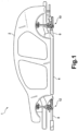
- FIG. 1 is a side view showing a schematic configuration of the vehicle to which the suspension device for a vehicle according to the embodiment of the present invention has been applied
- FIG. 2 is a perspective view showing, separated above and below, a vehicle body in an upper part of the vehicle, and a battery assembly, a vehicle body frame, a front suspension device, and a rear suspension device in a lower part of the vehicle shown in FIG. 1 as seen from a side of and from obliquely above the vehicle.
- a vehicle 1 includes a vehicle body 2 constituted of a monocoque body in an upper part of the vehicle 1 and, below the vehicle body 2, a battery assembly 4 provided in a center portion in a vehicle front-rear direction, a rear vehicle body frame 6 which extends toward the rear of the vehicle from the battery assembly 4, a front vehicle body frame 8 which extends toward the front of the vehicle from the battery assembly 4, a rear suspension device 10 mounted to the rear vehicle body frame 6, and a front suspension device 12 mounted to the front vehicle body frame 8.
- the battery assembly 4 includes a battery case 14 and a battery main body (not illustrated). Although not illustrated in FIG. 1 and FIG. 2 , the battery case 14 further includes a cover member 14a which includes frame members of four sides constituted of extruded material or the like in the present embodiment, the battery main body being housed inside the frame members of four sides, the cover member 14a covering the battery main body from above and below.
- a cover member 14a which includes frame members of four sides constituted of extruded material or the like in the present embodiment, the battery main body being housed inside the frame members of four sides, the cover member 14a covering the battery main body from above and below.
- FIG. 3 is a perspective view showing the battery assembly, the vehicle body frame, and the rear suspension device in the lower part of the vehicle shown in FIG. 2 as seen from the rear of and from obliquely above the vehicle;
- FIG. 4 is a side view of a rear suspension device on a left side of the vehicle in the rear suspension device shown in FIG. 3 as seen from the left side of the vehicle;
- FIG. 5 is a bottom view of the rear suspension device on the left side of the vehicle in the rear suspension device shown in FIG. 3 as seen from below.
- the rear vehicle body frame 6 includes a base member 16 which is fixed to a rear end edge of the battery case 14, two rear side frames 18 which are integrally formed with the base member 16 by welding or the like and which extend in the vehicle front-rear direction, and two rear cross members 20 which are mounted to the rear side frames 18 by fastening using bolts, welding, and the like.
- the base member 16 of the rear vehicle body frame 6 is directly connected to a frame member 14b at the rear end edge of the battery case 14 by fastening using bolts, welding, and the like, and rigidity of a lower portion of the vehicle body is increased by the frame members of four sides of the battery case 14 and the rear vehicle body frame 6.
- the rear cross members 20 function as rear suspension support members 20a and 20b for supporting the rear suspension device 10.
- the rear suspension device 10 is mounted via the rear suspension support members 20a and 20b to the rear side frames 18 which are directly connected to the battery case 14.
- the front vehicle body frame 8 is configured in a similar manner to the rear vehicle body frame 6, and rigidity of the lower portion of the vehicle body is increased by the frame members of four sides of the battery case 14 and the front vehicle body frame 8.
- the vehicle body 2 constituted of a monocoque body in the upper portion of the vehicle 1 shown in FIG. 1 and FIG. 2 is mounted to the frame members of the four sides of the battery case 14, the rear cross member 20, the front cross member 26, and the like in the lower portion of the vehicle body by fastening using bolts, welding, and the like to be integrally constructed as the vehicle 1.
- a rear electric motor (motor) 30 which has a large output and which is to be used as a main drive source is provided in a rear portion of the vehicle.
- the rear electric motor 30 is connected to rear wheels 34 (indicated by imaginary lines in FIG. 4 and FIG. 5 ) via two output transmission shafts 32 which extend to the left and the right from the rear electric motor 30 and drives the rear wheels 34.
- the rear wheels are main drive wheels.
- a front electric motor (motor) 36 which has a smaller output than the rear electric motor 30 and which is to be used as an auxiliary drive source is provided in a front portion of the vehicle.
- the front electric motor 36 is connected to front wheels via two output transmission shafts which extend to the left and the right from the front electric motor 36 and drives the front wheels. Accordingly, in the vehicle 1 according to the present embodiment, the front wheels are auxiliary drive wheels.
- FIG. 4 and FIG. 5 show the rear suspension device 10 on a left side of the vehicle. Since the rear suspension device 10 on a right side of the vehicle shares a same configuration as the rear suspension device 10 on the left side of the vehicle, hereinafter, a description of the rear suspension device 10 on the right side of the vehicle will be omitted.
- the rear suspension device 10 includes a hub carrier 42 for supporting the rear wheel 34.
- a hub carrier 42 for supporting the rear wheel 34.
- an opening which holds a hub 44 and which is to be penetrated by an output transmission shaft (axle) 32 is formed in a center portion thereof.
- the rear suspension device 10 includes a rear lower arm 46, a rear damper 48, and a toe control link 50 that are each coupled to the hub carrier 42.
- the rear damper 48 constitutes a shock absorber together with a coil spring 49.
- the rear suspension device 10 is positioned above a lower end of the battery case 14.
- the rear lower arm 46 is an A-shaped lower arm, and a distal end portion thereof on a side of the wheel 34 is coupled via a swinging shaft 52 to a portion which protrudes downward from a center portion of the hub carrier 42.
- the swinging shaft 52 is constituted of a pillow ball joint.
- each of the swinging shafts 54 and 56 is constituted of a bush housing, elastic bushing, a bolt shaft mounted on a vehicle body side, and the like.
- a position of each of the swinging shafts 54 and 56 is set such that a swinging axis A formed by each of the swinging shafts 54 and 56 extends in a direction coinciding with the vehicle front-rear direction in a bottom view (plan view).
- each of the swinging shafts 54 and 56 are set such that the swinging axis A formed by each of the swinging shafts 54 and 56 extends in an inclined manner in a direction of a predetermined obliquely-upward angle toward the front of the vehicle in a side view.
- a lower end portion of the rear damper 48 is mounted in a vehicle up-down direction in a distal end portion of a portion extending inward in the vehicle width direction above a center portion of the hub carrier 42.
- an upper end portion of the rear damper 48 is mounted to the vehicle body 2.
- the rear damper 48 is mounted to the hub carrier 42 and the vehicle body 2 so that a longitudinal direction axis B of the rear damper 48 (a direction of extension of the rear damper 48) vertically extends in a direction of 90 degrees relative to a direction of extension of the swinging axis A in a side view.
- the toe control link 50 is coupled to a portion which protrudes rearward from a center portion of the hub carrier 42.
- the front suspension device 12 is also constituted of a hub carrier, a lower arm, a damper, a tie rod, and the like similar to those of the rear suspension device 10 and shares a similar geometry with the rear suspension device 10.
- FIG. 6 is a conceptual diagram for explaining a relationship between an anti-tail-lift angle during friction braking and an anti-tail-lift angle during regenerative braking according to a comparative example (A) and the embodiment of the present invention (B).
- FIG. 6 shows the rear suspension device 10 (100).
- the front suspension device 12 since the front suspension device 12 also shares a same geometric configuration as the rear suspension device 10, hereinafter, a description of the front suspension device 12 will be omitted.
- FIG. 6 shows a state of each portion when the vehicle is stationary (a 1G state).
- FIG. 3 to FIG. 5 described above also show a state of each portion when the vehicle is stationary.
- an instantaneous center of rotation Ic of the rear suspension device 100 is set to be positioned higher than and closer to the inside of the vehicle than the rear suspension device 100 in a side view so that a predetermined anti-tail-lift force is obtained during braking.
- the instantaneous center of rotation Ic is an intersection of an imaginary line C1 which is perpendicular to a longitudinal direction axis of a rear damper and a swinging axis A1 of a lower arm.
- an anti-tail-lift angle is an angle of a line (indicated by a dashed line in FIG. 6(A) ) connecting the instantaneous center of rotation Ic and the wheel center Wc to each other relative to the ground G.
- friction brakes such as disk brakes inside the wheels
- the anti-tail-lift angle is an angle of a line (indicated by a dashed line in FIG. 6(A) ) connecting the instantaneous center of rotation Ic and the center of tire-ground contact Gc to each other relative to the ground G.
- a reference sign T1 denotes a trajectory of motion of the rear wheel
- the swing trajectory T1 is a trajectory which extends in an arc shape in a direction perpendicular to the line connecting the instantaneous center of rotation Ic and the wheel center Wc to each other.
- the longitudinal direction axis B of the rear damper 48 extends perpendicular to the swinging axis A in a side view and, accordingly, an imaginary line C which is perpendicular to the longitudinal direction axis B of the rear damper 48 extends parallel to the swinging axis A.
- the swinging axis A extends in a direction coinciding with the vehicle front-rear direction in a bottom view (plan view).
- a ball joint 52 of the rear lower arm 46 and the rear wheel 34 linearly swing (a swing trajectory thereof is denoted by a reference sign T) in an up-down direction which coincides with a direction of extension of the longitudinal direction axis B of the rear damper 48. Since the rear lower arm 46 swings around the swinging axis A which extends in the vehicle front-rear direction, the swing trajectory T of the ball joint 52 on a wheel-side assumes a linear shape in a side view.
- the swinging axis A of the rear lower arm 46 is extended obliquely upward toward the front of the vehicle in a side view and, accordingly, an anti-lift angle is formed in the rear suspension device 10.
- an anti-tail-lift angle when using regenerative brakes and an anti-tail-lift angle when using friction brakes in the vehicle 1 with an electric motor are made to be similar angles. Accordingly, in the present embodiment, for example, during coordinated control of the friction brakes and the regenerative brakes, a change in a pitching behavior of the rear portion of the vehicle is suppressed to stabilize the behavior of the vehicle.
- a linear swing direction (trajectory of motion) T of the rear wheel 34 and the longitudinal direction axis B of the rear damper are made to coincide with each other. Accordingly, in the present embodiment, a load transmitted from the rear wheel 34 is efficiently input to the rear damper 48 via the hub carrier 42 to operate the rear damper 48 in an efficient manner.
- the drive of the rear wheel 34 is used as a main drive by using the rear electric motor 30 as a main drive source with a large output, as shown in FIG. 6(B) , due to the anti-lift angle formed in the rear suspension device 10, a lift of particularly the rear portion of the vehicle body can be suppressed during use of the regenerative brakes and the friction brakes.
- the technical idea of the present invention is to, firstly, extend a damper 48 in a direction perpendicular to a swinging axis A and cause an imaginary line C which is perpendicular to a longitudinal direction axis B of the damper 48 to extend in a direction parallel to the swinging axis A in a side view so as to create a state where an instantaneous center of rotation does not exist or to make an instantaneous center of rotation at a position separated by an infinite distance (in particular, with respect to a position of an instantaneous center of rotation Ic such as that shown in FIG. 6(A) ) and, accordingly, suppress a change in a pitching behavior of a vehicle even when braking forces of regenerative brakes and friction brakes are changed.
- the technical idea of the present invention is to, secondly, cause the swinging axis A to extend in a vehicle front-rear direction in a bottom view (plan view) so as to create a state where an instantaneous center of rotation does not exist or to make an instantaneous center of rotation at a position separated by an infinite distance (in particular, with respect to a position of an instantaneous center of rotation Ic such as that shown in FIG. 6(A) ) and, accordingly, suppress a change in a pitching behavior of the vehicle even when braking forces of regenerative brakes and friction brakes are changed.
- the technical idea of the present invention is to, thirdly, form an anti-lift angle by causing the swinging axis A to extend obliquely upward toward a front of the vehicle in a side view and, accordingly, suppress a change in a pitching behavior of the vehicle (in particular, a change in a pitching behavior of a rear portion of the vehicle) during coordinated control of the regenerative brakes and the friction brake and the like.
- the technical idea of the present invention is to, fourthly, cause the swinging axis A to extend in the vehicle front-rear direction in a bottom view (plan view) and, at the same time, cause the damper 48 to extend in a direction perpendicular to the swinging axis A in a side view so that a linear swing direction (trajectory of motion) T of the rear wheel 34 (ball joint 52) and the longitudinal direction axis B of a rear damper coincide with each other and, accordingly, enable a load transmitted from the rear wheel 34 to be efficiently input to the rear damper 48.
- an angle of the longitudinal direction axis B of the damper relative to the swinging axis A in a side view, parallelism of the swinging axis A and the imaginary line C in a side view, and a direction of extension of the swinging axis A in a bottom view are important.
- these values are not limited to those in the embodiment described above and, for example, when designing a vehicle, performing an experiment with a test vehicle, or the like, the values may be adjusted to ranges (angle, parallelism, and direction) in which a change in a pitching behavior of the vehicle can be substantially suppressed during coordinated control of friction brakes and regenerative brakes and the like in consideration of a length of a wheel base or a position of the center of gravity of the vehicle, motion of each portion during swinging of the suspension, and the like which affect the pitching behavior of the vehicle.
- the angle formed by the swinging axis A and the longitudinal direction axis B of the rear damper 48 is preferably set to a range of 90° ⁇ 2.5°.
- only the front electric motor 36 may be provided as the electric motor to drive the front wheels 40 and make the vehicle 1 a front-wheel drive vehicle
- only the rear electric motor 30 may be provided as the electric motor to drive the rear wheels 34 and make the vehicle 1 a rear-wheel drive vehicle
- the front wheels 40 and the rear wheels 34 may be driven by a single electric motor.
- the present invention is not limited to the strut-type suspension device described above and can also be applied to suspension devices of other types.
- a double wishbone-type suspension device by causing a swinging axis of a lower arm and a swinging axis of an upper arm to extend in directions parallel to each other in a side view and causing the swinging axes to extend in a direction coinciding with the vehicle front-rear direction in a bottom view (plan view), a similar effect of suppressing a change in a pitching behavior of the vehicle even when braking forces of regenerative brakes and friction brakes are changed can be obtained.
- a similar effect can also be obtained by a measure of causing each swinging axis to extend obliquely upward toward the front of the vehicle in a side view.
- the present embodiment is a suspension device 10 for a vehicle 1 equipped with an electric motor 30 for transmitting a drive force to wheels 34 via an output transmission shaft 32, the suspension device 10 including: a suspension arm 46 which is coupled to a vehicle body side and a wheel side and which is capable of swinging in a vehicle up-down direction; and a damper 48 which extends in a direction perpendicular to a swinging axis A in a vehicle body-side mounting portion of the suspension arm 46 in a side view, wherein the swinging axis A of the suspension arm 46 and an imaginary line C perpendicular to a direction of extension of the damper 48 extend in a direction parallel to each other in a side view.
- a change in a pitching behavior of the vehicle can be suppressed even when a braking force of the regenerative brakes and a braking force of the friction brakes are changed during, for example, coordinated control of the regenerative brakes and the friction brakes.
- the swinging axis A of the suspension arm 46 extends in a direction coinciding with the vehicle front-rear direction in a bottom view, a change in the behavior of the vehicle 1 during use of the regenerative brakes and the friction brakes can be suppressed more reliably and a sense of discomfort imparted to an occupant can be reduced.
- a wheel 34 (a wheel center Wc) can be made to linearly swing in a same direction as a direction of extension of a longitudinal direction axis B of the damper 48 and, accordingly, a change in the behavior of the vehicle 1 during use of the regenerative brakes and the friction brakes can be suppressed more effectively.
- the suspension device of the vehicle 1 is a rear suspension device 10 for the rear wheel 34 as a main drive wheel and the swinging axis A of the suspension arm 46 of the rear suspension device 10 extends obliquely upward in an inclined manner toward a front of the vehicle in a side view, an anti-lift angle can be formed in the rear suspension device 10. Due to such an anti-lift angle, particularly, a lift of the rear portion of the vehicle body during use of the regenerative brakes and the friction brakes is suppressed and, accordingly, a change in the pitching behavior of the vehicle 1 during use of the regenerative brakes and the friction brakes can be suppressed more effectively.
- the suspension arm 46 is mounted to a rear vehicle body frame 6 directly connected to a rear end portion 14b of a battery case 14 in a lower portion of a center of the vehicle (specifically, mounted (to a rear side frame 18 via rear suspension support members 20a and 20b) and, at the same time, the suspension arm 46 is positioned above a lower end of the battery case 14, support rigidity of the wheel 34 can be enhanced and a response delay to vehicle behavior (for example, a response delay to a cornering force) can be reduced.
- the rear suspension device 10 is a strut-type suspension device including a hub carrier 42 in which an opening for allowing penetration by and for holding an output transmission shaft 32 is formed in a center portion thereof and which supports the wheel 34, wherein a lower portion of the damper 48 is mounted to the hub carrier 42, and an upper portion of the damper 48 is mounted to the vehicle body 2, a change in the behavior of the vehicle during use of the regenerative brakes and the friction brakes can be suppressed with the strut-type suspension which is a relatively simple construction.
Landscapes
- Engineering & Computer Science (AREA)
- Mechanical Engineering (AREA)
- Chemical & Material Sciences (AREA)
- Combustion & Propulsion (AREA)
- Transportation (AREA)
- Vehicle Body Suspensions (AREA)
Applications Claiming Priority (1)
| Application Number | Priority Date | Filing Date | Title |
|---|---|---|---|
| JP2022070037A JP2023160024A (ja) | 2022-04-21 | 2022-04-21 | 車両のサスペンション装置 |
Publications (1)
| Publication Number | Publication Date |
|---|---|
| EP4265444A1 true EP4265444A1 (fr) | 2023-10-25 |
Family
ID=85775936
Family Applications (1)
| Application Number | Title | Priority Date | Filing Date |
|---|---|---|---|
| EP23164211.7A Withdrawn EP4265444A1 (fr) | 2022-04-21 | 2023-03-27 | Dispositif de suspension pour véhicule |
Country Status (4)
| Country | Link |
|---|---|
| US (1) | US20230339275A1 (fr) |
| EP (1) | EP4265444A1 (fr) |
| JP (1) | JP2023160024A (fr) |
| CN (1) | CN116923021A (fr) |
Families Citing this family (3)
| Publication number | Priority date | Publication date | Assignee | Title |
|---|---|---|---|---|
| US12409718B2 (en) * | 2021-09-09 | 2025-09-09 | Oshkosh Corporation | Structural refuse vehicle body with undermounted batteries |
| US12319356B2 (en) * | 2021-09-30 | 2025-06-03 | Mazda Motor Corporation | Electric-vehicle-body structure having a center frame that is higher than a floor panel |
| US12233946B2 (en) * | 2021-09-30 | 2025-02-25 | Mazda Motor Corporation | Vehicle-body structure including a cross member at a rear portion of the floor panel |
Citations (5)
| Publication number | Priority date | Publication date | Assignee | Title |
|---|---|---|---|---|
| US4341396A (en) * | 1978-11-14 | 1982-07-27 | Regie Nationale Des Usines Renault | Front axle assembly for automobile |
| DE102012010897B3 (de) * | 2012-06-01 | 2013-11-07 | Volkswagen Aktiengesellschaft | Batteriekasten sowie Fahrzeug umfassend einen Batteriekasten |
| US20180001725A1 (en) * | 2016-07-04 | 2018-01-04 | Mazda Motor Corporation | Rear suspension structure of automotive vehicle |
| DE102019216990A1 (de) * | 2019-11-05 | 2021-05-06 | Volkswagen Aktiengesellschaft | Fahrschemel eines Kraftfahrzeuges mit integriertem Batteriekasten, Kraftfahrzeug mit einem solchen Fahrschemel sowie Verfahren zur elektrischen Kontaktierung eines Antriebsenergiespeichers |
| GB2598578A (en) * | 2020-09-02 | 2022-03-09 | Jaguar Land Rover Ltd | Suspension assembly |
Family Cites Families (2)
| Publication number | Priority date | Publication date | Assignee | Title |
|---|---|---|---|---|
| DE102010043901A1 (de) * | 2010-11-15 | 2012-05-16 | Bayerische Motoren Werke Aktiengesellschaft | Elektrisch angetriebene Achse eines zweispurigen Fahrzeugs |
| JP6195069B2 (ja) * | 2014-03-18 | 2017-09-13 | マツダ株式会社 | 車両のサスペンションの取付構造 |
-
2022
- 2022-04-21 JP JP2022070037A patent/JP2023160024A/ja active Pending
-
2023
- 2023-03-09 CN CN202310219705.1A patent/CN116923021A/zh active Pending
- 2023-03-24 US US18/189,649 patent/US20230339275A1/en not_active Abandoned
- 2023-03-27 EP EP23164211.7A patent/EP4265444A1/fr not_active Withdrawn
Patent Citations (6)
| Publication number | Priority date | Publication date | Assignee | Title |
|---|---|---|---|---|
| US4341396A (en) * | 1978-11-14 | 1982-07-27 | Regie Nationale Des Usines Renault | Front axle assembly for automobile |
| DE102012010897B3 (de) * | 2012-06-01 | 2013-11-07 | Volkswagen Aktiengesellschaft | Batteriekasten sowie Fahrzeug umfassend einen Batteriekasten |
| US20180001725A1 (en) * | 2016-07-04 | 2018-01-04 | Mazda Motor Corporation | Rear suspension structure of automotive vehicle |
| JP2018002000A (ja) | 2016-07-04 | 2018-01-11 | マツダ株式会社 | 自動車のリヤサスペンション構造 |
| DE102019216990A1 (de) * | 2019-11-05 | 2021-05-06 | Volkswagen Aktiengesellschaft | Fahrschemel eines Kraftfahrzeuges mit integriertem Batteriekasten, Kraftfahrzeug mit einem solchen Fahrschemel sowie Verfahren zur elektrischen Kontaktierung eines Antriebsenergiespeichers |
| GB2598578A (en) * | 2020-09-02 | 2022-03-09 | Jaguar Land Rover Ltd | Suspension assembly |
Also Published As
| Publication number | Publication date |
|---|---|
| CN116923021A (zh) | 2023-10-24 |
| US20230339275A1 (en) | 2023-10-26 |
| JP2023160024A (ja) | 2023-11-02 |
Similar Documents
| Publication | Publication Date | Title |
|---|---|---|
| US20230339275A1 (en) | Suspension device for vehicle | |
| CN107571698B (zh) | 汽车的前悬架构造 | |
| CN111032374B (zh) | 用于机动车的车轮悬架 | |
| JP2518349B2 (ja) | 車輌用リヤサスペンション | |
| JP2604147B2 (ja) | 自動車のサスペンシヨン装置 | |
| EP1888355B1 (fr) | Systemes de suspension | |
| CN110997356A (zh) | 具有布置在中央的驱动单元的车轴 | |
| KR20010057514A (ko) | 차량용 토션 빔 타입 현가장치의 토션 빔 마운팅 구조 | |
| EP4265445B1 (fr) | Dispositif de suspension pour véhicule | |
| CN215971001U (zh) | 一种整体桥式瓦特连杆复合悬架 | |
| CN117698352A (zh) | 五连杆悬架系统及车辆 | |
| JPH1142917A (ja) | 車両用懸架装置 | |
| KR200206928Y1 (ko) | 자동차 현가장치의 로워 컨트롤 아암 | |
| KR102919554B1 (ko) | 차량의 현가장치용 캐리어 | |
| CN113895199B (zh) | 一种整体桥式瓦特连杆复合悬架 | |
| KR100308955B1 (ko) | 자동차의 현가장치 | |
| KR100316888B1 (ko) | 자동차의 트레일링 아암형 현가장치 | |
| JP2604149B2 (ja) | 自動車のサスペンシヨン装置 | |
| JP2607077B2 (ja) | 自動車のサスペンシヨン装置 | |
| KR20240164081A (ko) | 모듈 조립이 가능한 차체구조 | |
| JP2604151B2 (ja) | 自動車のサスペンシヨン装置 | |
| JP2604150B2 (ja) | 自動車のサスペンシヨン装置 | |
| JPH0427042B2 (fr) | ||
| KR100221100B1 (ko) | 차량의 전륜구동형 후륜 현가장치 | |
| JP2604148B2 (ja) | 自動車のサスペンシヨン装置 |
Legal Events
| Date | Code | Title | Description |
|---|---|---|---|
| STAA | Information on the status of an ep patent application or granted ep patent |
Free format text: STATUS: THE APPLICATION HAS BEEN PUBLISHED |
|
| PUAI | Public reference made under article 153(3) epc to a published international application that has entered the european phase |
Free format text: ORIGINAL CODE: 0009012 |
|
| AK | Designated contracting states |
Kind code of ref document: A1 Designated state(s): AL AT BE BG CH CY CZ DE DK EE ES FI FR GB GR HR HU IE IS IT LI LT LU LV MC ME MK MT NL NO PL PT RO RS SE SI SK SM TR |
|
| STAA | Information on the status of an ep patent application or granted ep patent |
Free format text: STATUS: REQUEST FOR EXAMINATION WAS MADE |
|
| 17P | Request for examination filed |
Effective date: 20240403 |
|
| RBV | Designated contracting states (corrected) |
Designated state(s): AL AT BE BG CH CY CZ DE DK EE ES FI FR GB GR HR HU IE IS IT LI LT LU LV MC ME MK MT NL NO PL PT RO RS SE SI SK SM TR |
|
| 18W | Application withdrawn |
Effective date: 20240620 |