EP4265534B1 - Auskleidungs-crimpeinrichtung - Google Patents
Auskleidungs-crimpeinrichtung Download PDFInfo
- Publication number
- EP4265534B1 EP4265534B1 EP23159394.8A EP23159394A EP4265534B1 EP 4265534 B1 EP4265534 B1 EP 4265534B1 EP 23159394 A EP23159394 A EP 23159394A EP 4265534 B1 EP4265534 B1 EP 4265534B1
- Authority
- EP
- European Patent Office
- Prior art keywords
- socket
- cover
- plug
- limbs
- components
- Prior art date
- Legal status (The legal status is an assumption and is not a legal conclusion. Google has not performed a legal analysis and makes no representation as to the accuracy of the status listed.)
- Active
Links
Images





Classifications
-
- B—PERFORMING OPERATIONS; TRANSPORTING
- B65—CONVEYING; PACKING; STORING; HANDLING THIN OR FILAMENTARY MATERIAL
- B65B—MACHINES, APPARATUS OR DEVICES FOR, OR METHODS OF, PACKAGING ARTICLES OR MATERIALS; UNPACKING
- B65B7/00—Closing containers or receptacles after filling
- B65B7/02—Closing containers or receptacles deformed by, or taking-up shape, of, contents, e.g. bags, sacks
- B65B7/06—Closing containers or receptacles deformed by, or taking-up shape, of, contents, e.g. bags, sacks by collapsing mouth portion, e.g. to form a single flap
-
- B—PERFORMING OPERATIONS; TRANSPORTING
- B65—CONVEYING; PACKING; STORING; HANDLING THIN OR FILAMENTARY MATERIAL
- B65B—MACHINES, APPARATUS OR DEVICES FOR, OR METHODS OF, PACKAGING ARTICLES OR MATERIALS; UNPACKING
- B65B51/00—Devices for, or methods of, sealing or securing package folds or closures; Devices for gathering or twisting wrappers, or necks of bags
- B65B51/04—Applying separate sealing or securing members, e.g. clips
- B65B51/046—Applying a closure element to the mouths of bags
-
- B—PERFORMING OPERATIONS; TRANSPORTING
- B65—CONVEYING; PACKING; STORING; HANDLING THIN OR FILAMENTARY MATERIAL
- B65B—MACHINES, APPARATUS OR DEVICES FOR, OR METHODS OF, PACKAGING ARTICLES OR MATERIALS; UNPACKING
- B65B61/00—Auxiliary devices, not otherwise provided for, for operating on sheets, blanks, webs, binding material, containers or packages
- B65B61/04—Auxiliary devices, not otherwise provided for, for operating on sheets, blanks, webs, binding material, containers or packages for severing webs, or for separating joined packages
- B65B61/06—Auxiliary devices, not otherwise provided for, for operating on sheets, blanks, webs, binding material, containers or packages for severing webs, or for separating joined packages by cutting
-
- B—PERFORMING OPERATIONS; TRANSPORTING
- B65—CONVEYING; PACKING; STORING; HANDLING THIN OR FILAMENTARY MATERIAL
- B65D—CONTAINERS FOR STORAGE OR TRANSPORT OF ARTICLES OR MATERIALS, e.g. BAGS, BARRELS, BOTTLES, BOXES, CANS, CARTONS, CRATES, DRUMS, JARS, TANKS, HOPPERS, FORWARDING CONTAINERS; ACCESSORIES, CLOSURES, OR FITTINGS THEREFOR; PACKAGING ELEMENTS; PACKAGES
- B65D33/00—Details of, or accessories for, sacks or bags
- B65D33/16—End- or aperture-closing arrangements or devices
- B65D33/1616—Elements constricting the neck of the bag
-
- B—PERFORMING OPERATIONS; TRANSPORTING
- B65—CONVEYING; PACKING; STORING; HANDLING THIN OR FILAMENTARY MATERIAL
- B65B—MACHINES, APPARATUS OR DEVICES FOR, OR METHODS OF, PACKAGING ARTICLES OR MATERIALS; UNPACKING
- B65B51/00—Devices for, or methods of, sealing or securing package folds or closures; Devices for gathering or twisting wrappers, or necks of bags
- B65B51/04—Applying separate sealing or securing members, e.g. clips
Definitions
- the present invention relates to crimping of liners such as the mouths of plastics liner film for containers of powders in any industry where required.
- EP2112084 (Fette GmbH ), EP2468651 (V. Schnyder ), GB2464116 (Heaton Green Containment Ltd .), and US2012/0159741 (Schnyder ).
- Objectives of the present invention are to provide a crimp device which is simpler to use, and/or provides improved sealing of the liner opening, and/or requires fewer components.
- a bag or liner film crimping device comprising:
- the cover is dual-purpose and includes at least one tine for, in a second use after removal from said covering position, prising a socket limb from the plug as the cover is pressed distally.
- the cover comprises at least two tines, at least one for each interface between a socket limb and the plug.
- the cover comprises the top wall, and an end wall, and the tines extend from the end wall.
- the socket includes recesses to accommodate the tines when the cover is in the covering position.
- at least one limb of said socket top and bottom components has inwardly directed teeth.
- At least one plug component has outwardly directed teeth for engagement with the teeth of the socket.
- the cover and the plug lower component are configured to engage each other to be removed as a unit to expose the socket lower component limbs and allow removal of a liner through the socket in the proximal direction.
- the plug lower component and the cover comprises snap-fitting features configured for engaging together when the cover has been pressed distally to prise the socket limbs apart.
- said features comprise ridges on the plug or the cover and slots in the plug or the cover.
- the socket is symmetrical about a lateral plane in the proximal-distal direction and being through the socket bridge, and wherein the plug is symmetrical about a lateral plane in the proximal-distal direction and being through the plug bridge, whereby the first and second components are interchangeable.
- the device comprises at least two covers, one configured to act as a cover for the bottom socket component and one configured to act as a cover for the top component, after separation of said components.
- the cover is dual-purpose and includes at least one tine
- the method comprises further steps of removing the cover from the covering position and pressing the cover distally so that its tines prise open the socket limbs, and releasing the crimped film.
- the cover is dual-purpose and includes at least one tine for, in a second use, prising a socket limb from the plug as the cover is pressed distally.
- the cover comprises at least two tines, at least one for each interface between a socket limb and the plug.
- the cover comprises the top wall and an end wall, and the tines extend from the end wall.
- the socket includes recesses to accommodate the tines when the cover is in the covering position.
- at least one limb of said socket top and bottom components has inwardly directed teeth.
- at least one plug component has outwardly directed teeth for engagement with the teeth of the socket.
- the cover is dual-purpose and includes at least one tine, and the method comprises further steps of removing the cover and pressing the cover distally so that its tines prise open the socket limbs and releasing the crimped film.
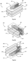
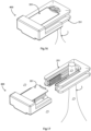
- a liner crimping device 1 comprises a U-shaped socket 200, a plug 300, and a cover 400.
- the plug 300 is configured to fit within the U-shaped socket so that the closed end and limbs of the socket 200 form an enclosure together with the leading end of the plug 300 to crimp the neck of a film liner.
- the open end of the socket 200 is defined as being the proximal end, the closed end of the socket being the distal end, whereby the plug 300 is pushed distally into the socket for crimping.
- the plug 300 has top and bottom halves or components 301 and 351 corresponding to the socket halves 201 and 251 respectively.
- the components are joined by a bridge 302 at the distal end.
- the plug top half 301 has laterally outwardly facing lines of teeth 303 and 304, and the bottom half 351 has corresponding lines of teeth 353 and 354.
- the teeth of the plug 300 are matched for engagement with the teeth of the socket 200 when the plug is pressed into the socket, and the plug 300 is configured to be a press-fit in the socket with force from a tool being required for pushing the plug distally into the socket for complete engagement for crimping.
- the plug 300 has top and bottom plates 305 and 355 which provide exposed top and bottom surfaces, and which overhang the lines of teeth and, in use, overlie parts of the top and bottom surfaces of the plug 200 alongside the teeth.
- the plug 300 also has snap-fit lugs 308 and 358, which engage with corresponding recesses in the socket for snap-fitting engagement.
- the cover 400 is configured to fit around the closed end of the socket, with a web 401 overlying the closed end of the socket and the leading end of the plug-in use, and hance covering exposed edges of crimped and cut film, as described in more detail below.
- the cover 400 also has an end wall 402 for engaging the closed end of the socket, and a pair of prongs or tines 403 and 404 extend from the end wall 402. The prongs or tines 403 and 404 fit into the elongate recesses 270 and 271 of the socket 200 when the cover 400 is in the covering position.
- the cover is dual-purpose and as described in more detail below, it can be removed from the covering position and used as a tool to open the device because the tines 403 and 404 are configured and located so that they can engage the small space on each lateral side of the plug at its proximal end.
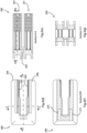
- the socket and plug top and bottom halves are separated by use of a scissorstype tool which cuts through the bridges 202 and 302 and the liner itself. That leaves the bottom halves 251 and 351 crimping the liner and the liner edges are exposed. This is shown in Fig. 8 .
- the top halves 201 and 301 with the excess liner may be discarded safely.
- the cover 300 is slid into position so that the wall 401 covers over the exposed liner edges, as shown in Figs. 9 and 10 .
- the cover may be left in situ for a prolonged period because the bag is fully sealed and there are no exposed liner or film edges.
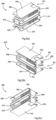
- the cover 400 When, subsequently, it is desired to open the crimp for access to the contents of the bag formed by the film the cover 400 is slid off the socket/plug combination, and is then pushed towards them from the opposed, proximal, side.
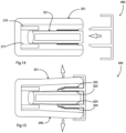
- the tines 403 and 404 are positioned, and have leading tapered ends, to engage in the small space on each side. These are indicated by the numerals 261 and 262. As shown in Figs. 12 to 15 the cover 400 is pushed distally, thereby prising the limbs 255 and 256 of the socket apart.
- a device 1000 has the same features as the device 1, with a socket lower component 1251 and a plug lower component 1351 together providing tine spaces 1261 and 1262, and a cover 1400.
- a lower face of the plug 1351 has a pair of ridges 1001 extending laterally and being symmetrically arranged about the longitudinal axis.
- the cover 1400 has a pair of slots 1002 arranged for snap-fitting engagement with the ridges 1001.
- the features 1001 and 1002 are configured so that they engage when the cover has been inserted fully home to open the socket lower component 1251.
- cover 1400 and the plug 1351 can be more easily removed as a unit to open the socket lower component 1251, thereby allowing it to be removed without disturbing the liner and hence minimising risk of powder being dislodged.
- Fig. 17 The arrows in this drawing show the liner being moved proximally, however it may be just as easily achieved by moving the socket distally without any movement of the liner.
- Figs. 19(a), (b), and (c) show an alternative device, comprising a socket 2200, a plug 2300, and a cover 2400.
- the socket 2200 has upper and lower components 2201 and 2252 which have teeth 2203 and 2253 which are shorter than those of the above devices.
- the top and bottom components are symmetrically arranged about a plane between them, being joined by the frangible bridge.
- the socket 2200 has a series of through holes 2260 extending from top to bottom. These holes 2260 allow a tie wrap to be trained through the socket for engagement with a security tag.
- the cover housing 2401 has a pair of ridges 2410 and 2411 for snap-fitting engagement in the slots 2304 and 2354 of the flanges of the bottom component.
- Some devices of the invention have two covers, one configured to act as a cover for the bottom components after separation, and one configured to act as a cover for the top components after separation.
- one cover can be used as described above for a bottom component and the other can be used to cover exposed liner in the top component after it is removed, just in case there are any particles which can dislodge from the part of the liner which is removed (see Fig. 8 ).
- the top and bottom components of both the socket and the plug are symmetrical about a lateral plane between them and through the frangible bridges, if a second cover is provided it may be used on either component.
- the devices 1 and 1000 For example, one cover could cover the top of the assembly in the lower part of Fig. 8 and the other could cover the underneath, hidden, side of the top assembly of Fig. 8 .
Landscapes
- Engineering & Computer Science (AREA)
- Mechanical Engineering (AREA)
- Closures For Containers (AREA)
Claims (15)
- Beutel- oder Inlinerfolien-Crimpvorrichtung, umfassend:eine Buchse (200) mit einer oberen und einer unteren Komponente (201, 251), die durch eine zerbrechliche Brücke (202) verbunden sind, wobei jede Komponente ein Paar gegenüberliegender Glieder (205/206, 255/256) aufweist, die sich proximal erstrecken, undeinen Stecker (300), der eine obere und eine untere Komponente (301, 351) aufweist, die durch eine zerbrechliche Brücke (302) verbunden und dafür gestaltet sind, mit einer Reibpassung in einer Bewegung von proximal an einem offenen Ende der Buchse zu distal im in die Buchse eingeführten Zustand zwischen die Glieder der Buchse zu passen,dadurch gekennzeichnet, dass die Vorrichtung ferner Folgendes umfasst:
eine Abdeckung (400), die eine obere Wand (401) umfasst und dafür gestaltet ist, über die untere Komponente der Buchse in eine Abdeckposition zu gleiten, in der die obere Wand (401) einen Raum am distalen Ende zwischen den Gliedern abdeckt, wenn die oberen und unteren Komponenten von Buchse und Stecker durch Brechen der Brücken (202, 302) nach dem Crimpen getrennt wurden. - Vorrichtung nach Anspruch 1, wobei die Abdeckung einem zweifachen Zweck dient und mindestens eine Zinke (403, 404) beinhaltet, um in einer zweiten Verwendung nach dem Entfernen aus der Abdeckposition ein Glied (255, 256) der Buchse aus dem Stecker zu schieben, wenn die Abdeckung (400) distal gedrückt wird.
- Vorrichtung nach Anspruch 2, wobei die Abdeckung mindestens zwei Zinken (403, 404) umfasst, mindestens eine für jede Grenzfläche (261, 262) zwischen einem Buchsenglied und dem Stecker.
- Vorrichtung nach Anspruch 2 oder 3, wobei die Abdeckung eine obere Wand (401) umfasst und eine Stirnwand (402) und sich die Zinken von der Stirnwand aus erstrecken.
- Vorrichtung nach einem der Ansprüche 2 bis 4, wobei die Buchse (200) Vertiefungen (270, 271) beinhaltet, um den Zinken Platz zu bieten, wenn sich die Abdeckung in der Abdeckposition befindet.
- Vorrichtung nach einem vorhergehenden Anspruch, wobei mindestens ein Glied der oberen und unteren Komponenten der Buchse nach innen gerichtete Zähne (203/204, 253/254) aufweist.
- Vorrichtung nach Anspruch 6, wobei mindestens eine Steckerkomponente nach außen gerichtete Zähne (303/304, 353/354) für einen Eingriff mit den Zähnen der Buchse aufweist.
- Vorrichtung nach einem vorhergehenden Anspruch, wobei die Abdeckung (400) und die untere Komponente (351) des Steckers dafür gestaltet sind, miteinander in Eingriff zu stehen, um als eine Einheit entfernt zu werden, um die Glieder der unteren Komponente (251) der Buchse freizulegen und das Entfernen eines Inliners durch die Buchse in der proximalen Richtung zu ermöglichen.
- Vorrichtung nach Anspruch 8, wobei die untere Komponente (1351) des Steckers und die Abdeckung (1400, 2400) Schnappverschlussmerkmale (1001, 1002, 2354, 2401, 2411) umfassen, die dafür gestaltet sind, miteinander in Eingriff zu stehen, wenn die Abdeckung distal gedrückt wurde, um die Buchsenglieder wegzuschieben.
- Vorrichtung nach Anspruch 9, wobei die Merkmale Rippen (1001) an dem Stecker oder der Abdeckung oder Schlitze (1002) in dem Stecker oder der Abdeckung umfassen.
- Vorrichtung nach einem vorhergehenden Anspruch, wobei die Buchse um eine Seitenebene in der Proximal-Distal-Richtung symmetrisch und durch die Buchsenbrücke ist und wobei der Stecker um eine Seitenebene in der Proximal-Distal-Richtung symmetrisch und durch die Steckerbrücke ist, wodurch die erste und die zweite Komponente austauschbar sind.
- Vorrichtung nach einem vorhergehenden Anspruch, wobei die Vorrichtung mindestens zwei Abdeckungen (400, 1400, 2400) umfasst, wobei eine dafür gestaltet ist, als eine Abdeckung für die untere Buchsenkomponente zu dienen, und eine dafür gestaltet ist, als Abdeckung für die obere Komponente zu dienen, nach dem Trennen der Komponenten.
- Verfahren zur Verwendung einer Vorrichtung nach einem vorhergehenden Anspruch, wobei das Verfahren Folgendes umfasst:Crimpen einer Folie in der Buchse durch distales Drücken des Steckers in die Buchse,Schneiden durch die Folie und die Brücken zwischen den oberen und unteren Komponenten von Buchse und Stecker undproximales Drücken der Abdeckung (400) auf die unteren Komponenten von Buchse und Stecker in eine Abdeckposition, so dass sie freiliegende Ränder der Folie abdeckt.
- Verfahren nach Anspruch 13, wobei die Abdeckung einem zweifachen Zweck dient und mindestens eine Zinke (403, 404) beinhaltet, und das Verfahren weitere Schritte des Entfernens der Abdeckung aus der Abdeckposition und des distalen Drückens der Abdeckung derart umfasst, dass ihre Zinken die Buchsenglieder auseinander schieben, und des Lösens der gecrimpten Folie.
- Verfahren nach Anspruch 14, wobei die Abdeckung und der Stecker zusammen entfernt werden und der Inliner (L) durch proximale Bewegung zwischen und weg von den Buchsengliedern entfernt wird und die Abdeckung distal gedrückt wird, bis Schnappverschlussmerkmale (1001, 1002) der Abdeckung und des Steckers in Eingriff gelangen.
Applications Claiming Priority (1)
| Application Number | Priority Date | Filing Date | Title |
|---|---|---|---|
| EP22160220 | 2022-03-04 |
Publications (3)
| Publication Number | Publication Date |
|---|---|
| EP4265534A1 EP4265534A1 (de) | 2023-10-25 |
| EP4265534B1 true EP4265534B1 (de) | 2024-11-20 |
| EP4265534C0 EP4265534C0 (de) | 2024-11-20 |
Family
ID=80628663
Family Applications (1)
| Application Number | Title | Priority Date | Filing Date |
|---|---|---|---|
| EP23159394.8A Active EP4265534B1 (de) | 2022-03-04 | 2023-03-01 | Auskleidungs-crimpeinrichtung |
Country Status (2)
| Country | Link |
|---|---|
| US (1) | US12304684B2 (de) |
| EP (1) | EP4265534B1 (de) |
Families Citing this family (1)
| Publication number | Priority date | Publication date | Assignee | Title |
|---|---|---|---|---|
| EP4265534B1 (de) * | 2022-03-04 | 2024-11-20 | Containment Service Providers Company Limited | Auskleidungs-crimpeinrichtung |
Family Cites Families (12)
| Publication number | Priority date | Publication date | Assignee | Title |
|---|---|---|---|---|
| DK250886A (da) * | 1986-05-29 | 1987-11-30 | Emc Tamaco As | Fremgangsmaade til taet afbinding af et indsnaevringssted paa en roerfolieemballage bestaaende af formstoffolie med hoej taethed, samt binder til brug herved |
| DE20117669U1 (de) * | 2001-10-29 | 2002-03-14 | GEA Buck Valve GmbH, 79379 Müllheim | Abgedichtete Andockeinrichtung insbesondere für Säcke |
| ITMI20030125A1 (it) * | 2003-01-27 | 2004-07-28 | Giulio Ghisolfi | Sistema a fermaglio per corpi fogliformi, e relativi metodi di fabbricazione e di montaggio. |
| DE10335325B4 (de) * | 2003-08-01 | 2007-05-03 | Gea Niro Gmbh | Kupplungsverschlüsse sowie Andockeinrichtungen enthaltend diese Kupplungsverschlüsse |
| FR2908882B1 (fr) | 2006-11-17 | 2008-12-26 | Thales Sa | Dispositif de mesure de la pression totale d'un ecoulement et procede mettant en oeuvre le dispositif |
| DE102008020747A1 (de) | 2008-04-23 | 2009-10-29 | Fette Gmbh | Verfahren zum Verschließen von Säcken aus Kunststoff und Klemmschelle zur Durchführung des Verfahrens |
| DE202008007187U1 (de) * | 2008-05-28 | 2008-08-07 | Wegen Gmbh | Vorrichtung zum Verbinden und Verschließen von rieselfähige Schüttgüter enthaltenden Behältern |
| GB2464116B (en) | 2008-10-03 | 2010-09-08 | Neal Hanley | Liner crimp |
| EP2374724B1 (de) * | 2010-04-09 | 2014-09-17 | Poly-clip System GmbH & Co. KG | Verschlussclip und Werkzeug zum Schließen des Clips |
| CH704272A2 (de) | 2010-12-24 | 2012-06-29 | Viktor Schnyder | Clip-Verschluss. |
| US9481493B2 (en) * | 2013-03-08 | 2016-11-01 | Joshua D. Vantrease | Interlock-able fingered closure clips |
| EP4265534B1 (de) * | 2022-03-04 | 2024-11-20 | Containment Service Providers Company Limited | Auskleidungs-crimpeinrichtung |
-
2023
- 2023-03-01 EP EP23159394.8A patent/EP4265534B1/de active Active
- 2023-03-02 US US18/177,436 patent/US12304684B2/en active Active
Also Published As
| Publication number | Publication date |
|---|---|
| US20230278734A1 (en) | 2023-09-07 |
| EP4265534C0 (de) | 2024-11-20 |
| US12304684B2 (en) | 2025-05-20 |
| EP4265534A1 (de) | 2023-10-25 |
Similar Documents
| Publication | Publication Date | Title |
|---|---|---|
| US4106801A (en) | One piece security seal and new sealing system | |
| US4598837A (en) | End closure with tamper evident element | |
| JPH0721127Y2 (ja) | スライドファスナーの封鎖装置 | |
| US11376371B2 (en) | Pen needle packaging | |
| US4567995A (en) | End closure having separate opening means. | |
| US4190175A (en) | Container and closure construction for resisting tampering | |
| US12304684B2 (en) | Liner crimp device | |
| CA2009192A1 (en) | Closure | |
| GB2161461A (en) | Container with lid | |
| JP2008506601A (ja) | 不正開封を表示する取出し口付き密封体 | |
| KR960701778A (ko) | 약물 용기용 클로저(closure for medication container) | |
| JPS5852052A (ja) | 蓋付きプラスチツク製容器 | |
| EP0141591B1 (de) | Verschluss | |
| GB2364695A (en) | Tamper proof container | |
| CZ285790B6 (cs) | Nádobka s víčkem | |
| FR2610082A1 (fr) | Systeme d'accouplement d'un appareil et d'une cartouche, et appareil a gaz incorporant un tel systeme | |
| KR20180058921A (ko) | 감염성 폐기물용 밀폐용기의 덮개구조 | |
| EP4525948A1 (de) | Verpackte nadelanordnung | |
| JP3535790B2 (ja) | 合成樹脂製包装容器 | |
| EP4279098A1 (de) | Verpackte nadelanordnung | |
| JPH0721564U (ja) | バイアルの密封閉鎖具 | |
| NO162505B (no) | Blisterpakning for delbare tabletter. | |
| US20090267303A1 (en) | Method for closing bags made of plastics and clamping clip for implementing the method | |
| JPH0739803Y2 (ja) | 合成樹脂製容器 | |
| US4690291A (en) | Barbed lid closure |
Legal Events
| Date | Code | Title | Description |
|---|---|---|---|
| PUAI | Public reference made under article 153(3) epc to a published international application that has entered the european phase |
Free format text: ORIGINAL CODE: 0009012 |
|
| STAA | Information on the status of an ep patent application or granted ep patent |
Free format text: STATUS: THE APPLICATION HAS BEEN PUBLISHED |
|
| AK | Designated contracting states |
Kind code of ref document: A1 Designated state(s): AL AT BE BG CH CY CZ DE DK EE ES FI FR GB GR HR HU IE IS IT LI LT LU LV MC ME MK MT NL NO PL PT RO RS SE SI SK SM TR |
|
| STAA | Information on the status of an ep patent application or granted ep patent |
Free format text: STATUS: REQUEST FOR EXAMINATION WAS MADE |
|
| 17P | Request for examination filed |
Effective date: 20240212 |
|
| RBV | Designated contracting states (corrected) |
Designated state(s): AL AT BE BG CH CY CZ DE DK EE ES FI FR GB GR HR HU IE IS IT LI LT LU LV MC ME MK MT NL NO PL PT RO RS SE SI SK SM TR |
|
| GRAP | Despatch of communication of intention to grant a patent |
Free format text: ORIGINAL CODE: EPIDOSNIGR1 |
|
| STAA | Information on the status of an ep patent application or granted ep patent |
Free format text: STATUS: GRANT OF PATENT IS INTENDED |
|
| RIC1 | Information provided on ipc code assigned before grant |
Ipc: B65D 33/16 20060101ALI20240611BHEP Ipc: B65B 51/04 20060101AFI20240611BHEP |
|
| INTG | Intention to grant announced |
Effective date: 20240710 |
|
| GRAS | Grant fee paid |
Free format text: ORIGINAL CODE: EPIDOSNIGR3 |
|
| GRAA | (expected) grant |
Free format text: ORIGINAL CODE: 0009210 |
|
| STAA | Information on the status of an ep patent application or granted ep patent |
Free format text: STATUS: THE PATENT HAS BEEN GRANTED |
|
| AK | Designated contracting states |
Kind code of ref document: B1 Designated state(s): AL AT BE BG CH CY CZ DE DK EE ES FI FR GB GR HR HU IE IS IT LI LT LU LV MC ME MK MT NL NO PL PT RO RS SE SI SK SM TR |
|
| REG | Reference to a national code |
Ref country code: GB Ref legal event code: FG4D |
|
| REG | Reference to a national code |
Ref country code: CH Ref legal event code: EP |
|
| REG | Reference to a national code |
Ref country code: DE Ref legal event code: R096 Ref document number: 602023001053 Country of ref document: DE |
|
| REG | Reference to a national code |
Ref country code: IE Ref legal event code: FG4D |
|
| U01 | Request for unitary effect filed |
Effective date: 20241121 |
|
| U07 | Unitary effect registered |
Designated state(s): AT BE BG DE DK EE FI FR IT LT LU LV MT NL PT RO SE SI Effective date: 20241128 |
|
| U20 | Renewal fee for the european patent with unitary effect paid |
Year of fee payment: 3 Effective date: 20250207 |
|
| PG25 | Lapsed in a contracting state [announced via postgrant information from national office to epo] |
Ref country code: IS Free format text: LAPSE BECAUSE OF FAILURE TO SUBMIT A TRANSLATION OF THE DESCRIPTION OR TO PAY THE FEE WITHIN THE PRESCRIBED TIME-LIMIT Effective date: 20250320 Ref country code: HR Free format text: LAPSE BECAUSE OF FAILURE TO SUBMIT A TRANSLATION OF THE DESCRIPTION OR TO PAY THE FEE WITHIN THE PRESCRIBED TIME-LIMIT Effective date: 20241120 |
|
| PG25 | Lapsed in a contracting state [announced via postgrant information from national office to epo] |
Ref country code: ES Free format text: LAPSE BECAUSE OF FAILURE TO SUBMIT A TRANSLATION OF THE DESCRIPTION OR TO PAY THE FEE WITHIN THE PRESCRIBED TIME-LIMIT Effective date: 20241120 |
|
| PG25 | Lapsed in a contracting state [announced via postgrant information from national office to epo] |
Ref country code: NO Free format text: LAPSE BECAUSE OF FAILURE TO SUBMIT A TRANSLATION OF THE DESCRIPTION OR TO PAY THE FEE WITHIN THE PRESCRIBED TIME-LIMIT Effective date: 20250220 |
|
| PG25 | Lapsed in a contracting state [announced via postgrant information from national office to epo] |
Ref country code: GR Free format text: LAPSE BECAUSE OF FAILURE TO SUBMIT A TRANSLATION OF THE DESCRIPTION OR TO PAY THE FEE WITHIN THE PRESCRIBED TIME-LIMIT Effective date: 20250221 |
|
| PG25 | Lapsed in a contracting state [announced via postgrant information from national office to epo] |
Ref country code: PL Free format text: LAPSE BECAUSE OF FAILURE TO SUBMIT A TRANSLATION OF THE DESCRIPTION OR TO PAY THE FEE WITHIN THE PRESCRIBED TIME-LIMIT Effective date: 20241120 |
|
| PG25 | Lapsed in a contracting state [announced via postgrant information from national office to epo] |
Ref country code: RS Free format text: LAPSE BECAUSE OF FAILURE TO SUBMIT A TRANSLATION OF THE DESCRIPTION OR TO PAY THE FEE WITHIN THE PRESCRIBED TIME-LIMIT Effective date: 20250220 |
|
| PG25 | Lapsed in a contracting state [announced via postgrant information from national office to epo] |
Ref country code: SM Free format text: LAPSE BECAUSE OF FAILURE TO SUBMIT A TRANSLATION OF THE DESCRIPTION OR TO PAY THE FEE WITHIN THE PRESCRIBED TIME-LIMIT Effective date: 20241120 |
|
| PG25 | Lapsed in a contracting state [announced via postgrant information from national office to epo] |
Ref country code: SK Free format text: LAPSE BECAUSE OF FAILURE TO SUBMIT A TRANSLATION OF THE DESCRIPTION OR TO PAY THE FEE WITHIN THE PRESCRIBED TIME-LIMIT Effective date: 20241120 |
|
| PG25 | Lapsed in a contracting state [announced via postgrant information from national office to epo] |
Ref country code: CZ Free format text: LAPSE BECAUSE OF FAILURE TO SUBMIT A TRANSLATION OF THE DESCRIPTION OR TO PAY THE FEE WITHIN THE PRESCRIBED TIME-LIMIT Effective date: 20241120 |
|
| PLBE | No opposition filed within time limit |
Free format text: ORIGINAL CODE: 0009261 |
|
| STAA | Information on the status of an ep patent application or granted ep patent |
Free format text: STATUS: NO OPPOSITION FILED WITHIN TIME LIMIT |
|
| PG25 | Lapsed in a contracting state [announced via postgrant information from national office to epo] |
Ref country code: MC Free format text: LAPSE BECAUSE OF FAILURE TO SUBMIT A TRANSLATION OF THE DESCRIPTION OR TO PAY THE FEE WITHIN THE PRESCRIBED TIME-LIMIT Effective date: 20241120 |
|
| 26N | No opposition filed |
Effective date: 20250821 |
|
| U20 | Renewal fee for the european patent with unitary effect paid |
Year of fee payment: 4 Effective date: 20260121 |
|
| PGFP | Annual fee paid to national office [announced via postgrant information from national office to epo] |
Ref country code: IE Payment date: 20260121 Year of fee payment: 4 |
|
| PG25 | Lapsed in a contracting state [announced via postgrant information from national office to epo] |
Ref country code: CY Free format text: LAPSE BECAUSE OF FAILURE TO SUBMIT A TRANSLATION OF THE DESCRIPTION OR TO PAY THE FEE WITHIN THE PRESCRIBED TIME-LIMIT Effective date: 20241120 |
|
| PG25 | Lapsed in a contracting state [announced via postgrant information from national office to epo] |
Ref country code: TR Free format text: LAPSE BECAUSE OF FAILURE TO SUBMIT A TRANSLATION OF THE DESCRIPTION OR TO PAY THE FEE WITHIN THE PRESCRIBED TIME-LIMIT Effective date: 20241120 |