EP4265957B1 - Installation de stockage de fluide cryogénique - Google Patents
Installation de stockage de fluide cryogénique Download PDFInfo
- Publication number
- EP4265957B1 EP4265957B1 EP23166460.8A EP23166460A EP4265957B1 EP 4265957 B1 EP4265957 B1 EP 4265957B1 EP 23166460 A EP23166460 A EP 23166460A EP 4265957 B1 EP4265957 B1 EP 4265957B1
- Authority
- EP
- European Patent Office
- Prior art keywords
- tank
- depth
- transfer element
- ground
- installation according
- Prior art date
- Legal status (The legal status is an assumption and is not a legal conclusion. Google has not performed a legal analysis and makes no representation as to the accuracy of the status listed.)
- Active
Links
Images
Classifications
-
- F—MECHANICAL ENGINEERING; LIGHTING; HEATING; WEAPONS; BLASTING
- F17—STORING OR DISTRIBUTING GASES OR LIQUIDS
- F17C—VESSELS FOR CONTAINING OR STORING COMPRESSED, LIQUEFIED OR SOLIDIFIED GASES; FIXED-CAPACITY GAS-HOLDERS; FILLING VESSELS WITH, OR DISCHARGING FROM VESSELS, COMPRESSED, LIQUEFIED, OR SOLIDIFIED GASES
- F17C3/00—Vessels not under pressure
- F17C3/005—Underground or underwater containers or vessels
-
- F—MECHANICAL ENGINEERING; LIGHTING; HEATING; WEAPONS; BLASTING
- F17—STORING OR DISTRIBUTING GASES OR LIQUIDS
- F17C—VESSELS FOR CONTAINING OR STORING COMPRESSED, LIQUEFIED OR SOLIDIFIED GASES; FIXED-CAPACITY GAS-HOLDERS; FILLING VESSELS WITH, OR DISCHARGING FROM VESSELS, COMPRESSED, LIQUEFIED, OR SOLIDIFIED GASES
- F17C13/00—Details of vessels or of the filling or discharging of vessels
- F17C13/001—Thermal insulation specially adapted for cryogenic vessels
-
- F—MECHANICAL ENGINEERING; LIGHTING; HEATING; WEAPONS; BLASTING
- F17—STORING OR DISTRIBUTING GASES OR LIQUIDS
- F17C—VESSELS FOR CONTAINING OR STORING COMPRESSED, LIQUEFIED OR SOLIDIFIED GASES; FIXED-CAPACITY GAS-HOLDERS; FILLING VESSELS WITH, OR DISCHARGING FROM VESSELS, COMPRESSED, LIQUEFIED, OR SOLIDIFIED GASES
- F17C13/00—Details of vessels or of the filling or discharging of vessels
- F17C13/10—Arrangements for preventing freezing
-
- F—MECHANICAL ENGINEERING; LIGHTING; HEATING; WEAPONS; BLASTING
- F17—STORING OR DISTRIBUTING GASES OR LIQUIDS
- F17C—VESSELS FOR CONTAINING OR STORING COMPRESSED, LIQUEFIED OR SOLIDIFIED GASES; FIXED-CAPACITY GAS-HOLDERS; FILLING VESSELS WITH, OR DISCHARGING FROM VESSELS, COMPRESSED, LIQUEFIED, OR SOLIDIFIED GASES
- F17C3/00—Vessels not under pressure
- F17C3/02—Vessels not under pressure with provision for thermal insulation
- F17C3/08—Vessels not under pressure with provision for thermal insulation by vacuum spaces, e.g. Dewar flask
-
- F—MECHANICAL ENGINEERING; LIGHTING; HEATING; WEAPONS; BLASTING
- F17—STORING OR DISTRIBUTING GASES OR LIQUIDS
- F17C—VESSELS FOR CONTAINING OR STORING COMPRESSED, LIQUEFIED OR SOLIDIFIED GASES; FIXED-CAPACITY GAS-HOLDERS; FILLING VESSELS WITH, OR DISCHARGING FROM VESSELS, COMPRESSED, LIQUEFIED, OR SOLIDIFIED GASES
- F17C2201/00—Vessel construction, in particular geometry, arrangement or size
- F17C2201/01—Shape
- F17C2201/0104—Shape cylindrical
- F17C2201/0109—Shape cylindrical with exteriorly curved end-piece
-
- F—MECHANICAL ENGINEERING; LIGHTING; HEATING; WEAPONS; BLASTING
- F17—STORING OR DISTRIBUTING GASES OR LIQUIDS
- F17C—VESSELS FOR CONTAINING OR STORING COMPRESSED, LIQUEFIED OR SOLIDIFIED GASES; FIXED-CAPACITY GAS-HOLDERS; FILLING VESSELS WITH, OR DISCHARGING FROM VESSELS, COMPRESSED, LIQUEFIED, OR SOLIDIFIED GASES
- F17C2201/00—Vessel construction, in particular geometry, arrangement or size
- F17C2201/03—Orientation
- F17C2201/035—Orientation with substantially horizontal main axis
-
- F—MECHANICAL ENGINEERING; LIGHTING; HEATING; WEAPONS; BLASTING
- F17—STORING OR DISTRIBUTING GASES OR LIQUIDS
- F17C—VESSELS FOR CONTAINING OR STORING COMPRESSED, LIQUEFIED OR SOLIDIFIED GASES; FIXED-CAPACITY GAS-HOLDERS; FILLING VESSELS WITH, OR DISCHARGING FROM VESSELS, COMPRESSED, LIQUEFIED, OR SOLIDIFIED GASES
- F17C2201/00—Vessel construction, in particular geometry, arrangement or size
- F17C2201/05—Size
- F17C2201/054—Size medium (>1 m3)
-
- F—MECHANICAL ENGINEERING; LIGHTING; HEATING; WEAPONS; BLASTING
- F17—STORING OR DISTRIBUTING GASES OR LIQUIDS
- F17C—VESSELS FOR CONTAINING OR STORING COMPRESSED, LIQUEFIED OR SOLIDIFIED GASES; FIXED-CAPACITY GAS-HOLDERS; FILLING VESSELS WITH, OR DISCHARGING FROM VESSELS, COMPRESSED, LIQUEFIED, OR SOLIDIFIED GASES
- F17C2201/00—Vessel construction, in particular geometry, arrangement or size
- F17C2201/05—Size
- F17C2201/056—Small (<1 m3)
-
- F—MECHANICAL ENGINEERING; LIGHTING; HEATING; WEAPONS; BLASTING
- F17—STORING OR DISTRIBUTING GASES OR LIQUIDS
- F17C—VESSELS FOR CONTAINING OR STORING COMPRESSED, LIQUEFIED OR SOLIDIFIED GASES; FIXED-CAPACITY GAS-HOLDERS; FILLING VESSELS WITH, OR DISCHARGING FROM VESSELS, COMPRESSED, LIQUEFIED, OR SOLIDIFIED GASES
- F17C2203/00—Vessel construction, in particular walls or details thereof
- F17C2203/03—Thermal insulations
- F17C2203/0391—Thermal insulations by vacuum
-
- F—MECHANICAL ENGINEERING; LIGHTING; HEATING; WEAPONS; BLASTING
- F17—STORING OR DISTRIBUTING GASES OR LIQUIDS
- F17C—VESSELS FOR CONTAINING OR STORING COMPRESSED, LIQUEFIED OR SOLIDIFIED GASES; FIXED-CAPACITY GAS-HOLDERS; FILLING VESSELS WITH, OR DISCHARGING FROM VESSELS, COMPRESSED, LIQUEFIED, OR SOLIDIFIED GASES
- F17C2203/00—Vessel construction, in particular walls or details thereof
- F17C2203/06—Materials for walls or layers thereof; Properties or structures of walls or their materials
- F17C2203/0602—Wall structures; Special features thereof
- F17C2203/0612—Wall structures
- F17C2203/0626—Multiple walls
- F17C2203/0629—Two walls
-
- F—MECHANICAL ENGINEERING; LIGHTING; HEATING; WEAPONS; BLASTING
- F17—STORING OR DISTRIBUTING GASES OR LIQUIDS
- F17C—VESSELS FOR CONTAINING OR STORING COMPRESSED, LIQUEFIED OR SOLIDIFIED GASES; FIXED-CAPACITY GAS-HOLDERS; FILLING VESSELS WITH, OR DISCHARGING FROM VESSELS, COMPRESSED, LIQUEFIED, OR SOLIDIFIED GASES
- F17C2205/00—Vessel construction, in particular mounting arrangements, attachments or identifications means
- F17C2205/01—Mounting arrangements
- F17C2205/0103—Exterior arrangements
- F17C2205/0115—Dismountable protective hulls
-
- F—MECHANICAL ENGINEERING; LIGHTING; HEATING; WEAPONS; BLASTING
- F17—STORING OR DISTRIBUTING GASES OR LIQUIDS
- F17C—VESSELS FOR CONTAINING OR STORING COMPRESSED, LIQUEFIED OR SOLIDIFIED GASES; FIXED-CAPACITY GAS-HOLDERS; FILLING VESSELS WITH, OR DISCHARGING FROM VESSELS, COMPRESSED, LIQUEFIED, OR SOLIDIFIED GASES
- F17C2221/00—Handled fluid, in particular type of fluid
- F17C2221/01—Pure fluids
- F17C2221/012—Hydrogen
-
- F—MECHANICAL ENGINEERING; LIGHTING; HEATING; WEAPONS; BLASTING
- F17—STORING OR DISTRIBUTING GASES OR LIQUIDS
- F17C—VESSELS FOR CONTAINING OR STORING COMPRESSED, LIQUEFIED OR SOLIDIFIED GASES; FIXED-CAPACITY GAS-HOLDERS; FILLING VESSELS WITH, OR DISCHARGING FROM VESSELS, COMPRESSED, LIQUEFIED, OR SOLIDIFIED GASES
- F17C2221/00—Handled fluid, in particular type of fluid
- F17C2221/03—Mixtures
- F17C2221/032—Hydrocarbons
- F17C2221/033—Methane, e.g. natural gas, CNG, LNG, GNL, GNC, PLNG
-
- F—MECHANICAL ENGINEERING; LIGHTING; HEATING; WEAPONS; BLASTING
- F17—STORING OR DISTRIBUTING GASES OR LIQUIDS
- F17C—VESSELS FOR CONTAINING OR STORING COMPRESSED, LIQUEFIED OR SOLIDIFIED GASES; FIXED-CAPACITY GAS-HOLDERS; FILLING VESSELS WITH, OR DISCHARGING FROM VESSELS, COMPRESSED, LIQUEFIED, OR SOLIDIFIED GASES
- F17C2223/00—Handled fluid before transfer, i.e. state of fluid when stored in the vessel or before transfer from the vessel
- F17C2223/01—Handled fluid before transfer, i.e. state of fluid when stored in the vessel or before transfer from the vessel characterised by the phase
- F17C2223/0146—Two-phase
- F17C2223/0153—Liquefied gas, e.g. LPG, GPL
- F17C2223/0161—Liquefied gas, e.g. LPG, GPL cryogenic, e.g. LNG, GNL, PLNG
-
- F—MECHANICAL ENGINEERING; LIGHTING; HEATING; WEAPONS; BLASTING
- F17—STORING OR DISTRIBUTING GASES OR LIQUIDS
- F17C—VESSELS FOR CONTAINING OR STORING COMPRESSED, LIQUEFIED OR SOLIDIFIED GASES; FIXED-CAPACITY GAS-HOLDERS; FILLING VESSELS WITH, OR DISCHARGING FROM VESSELS, COMPRESSED, LIQUEFIED, OR SOLIDIFIED GASES
- F17C2223/00—Handled fluid before transfer, i.e. state of fluid when stored in the vessel or before transfer from the vessel
- F17C2223/03—Handled fluid before transfer, i.e. state of fluid when stored in the vessel or before transfer from the vessel characterised by the pressure level
- F17C2223/033—Small pressure, e.g. for liquefied gas
-
- F—MECHANICAL ENGINEERING; LIGHTING; HEATING; WEAPONS; BLASTING
- F17—STORING OR DISTRIBUTING GASES OR LIQUIDS
- F17C—VESSELS FOR CONTAINING OR STORING COMPRESSED, LIQUEFIED OR SOLIDIFIED GASES; FIXED-CAPACITY GAS-HOLDERS; FILLING VESSELS WITH, OR DISCHARGING FROM VESSELS, COMPRESSED, LIQUEFIED, OR SOLIDIFIED GASES
- F17C2227/00—Transfer of fluids, i.e. method or means for transferring the fluid; Heat exchange with the fluid
- F17C2227/03—Heat exchange with the fluid
-
- F—MECHANICAL ENGINEERING; LIGHTING; HEATING; WEAPONS; BLASTING
- F17—STORING OR DISTRIBUTING GASES OR LIQUIDS
- F17C—VESSELS FOR CONTAINING OR STORING COMPRESSED, LIQUEFIED OR SOLIDIFIED GASES; FIXED-CAPACITY GAS-HOLDERS; FILLING VESSELS WITH, OR DISCHARGING FROM VESSELS, COMPRESSED, LIQUEFIED, OR SOLIDIFIED GASES
- F17C2260/00—Purposes of gas storage and gas handling
- F17C2260/03—Dealing with losses
- F17C2260/031—Dealing with losses due to heat transfer
- F17C2260/032—Avoiding freezing or defrosting
-
- F—MECHANICAL ENGINEERING; LIGHTING; HEATING; WEAPONS; BLASTING
- F17—STORING OR DISTRIBUTING GASES OR LIQUIDS
- F17C—VESSELS FOR CONTAINING OR STORING COMPRESSED, LIQUEFIED OR SOLIDIFIED GASES; FIXED-CAPACITY GAS-HOLDERS; FILLING VESSELS WITH, OR DISCHARGING FROM VESSELS, COMPRESSED, LIQUEFIED, OR SOLIDIFIED GASES
- F17C2270/00—Applications
- F17C2270/01—Applications for fluid transport or storage
- F17C2270/0142—Applications for fluid transport or storage placed underground
- F17C2270/0144—Type of cavity
- F17C2270/0147—Type of cavity by burying vessels
-
- F—MECHANICAL ENGINEERING; LIGHTING; HEATING; WEAPONS; BLASTING
- F17—STORING OR DISTRIBUTING GASES OR LIQUIDS
- F17C—VESSELS FOR CONTAINING OR STORING COMPRESSED, LIQUEFIED OR SOLIDIFIED GASES; FIXED-CAPACITY GAS-HOLDERS; FILLING VESSELS WITH, OR DISCHARGING FROM VESSELS, COMPRESSED, LIQUEFIED, OR SOLIDIFIED GASES
- F17C2270/00—Applications
- F17C2270/01—Applications for fluid transport or storage
- F17C2270/0142—Applications for fluid transport or storage placed underground
- F17C2270/0157—Location of cavity
- F17C2270/016—Location of cavity onshore
-
- F—MECHANICAL ENGINEERING; LIGHTING; HEATING; WEAPONS; BLASTING
- F17—STORING OR DISTRIBUTING GASES OR LIQUIDS
- F17C—VESSELS FOR CONTAINING OR STORING COMPRESSED, LIQUEFIED OR SOLIDIFIED GASES; FIXED-CAPACITY GAS-HOLDERS; FILLING VESSELS WITH, OR DISCHARGING FROM VESSELS, COMPRESSED, LIQUEFIED, OR SOLIDIFIED GASES
- F17C2270/00—Applications
- F17C2270/05—Applications for industrial use
- F17C2270/0563—Pneumatic applications
-
- Y—GENERAL TAGGING OF NEW TECHNOLOGICAL DEVELOPMENTS; GENERAL TAGGING OF CROSS-SECTIONAL TECHNOLOGIES SPANNING OVER SEVERAL SECTIONS OF THE IPC; TECHNICAL SUBJECTS COVERED BY FORMER USPC CROSS-REFERENCE ART COLLECTIONS [XRACs] AND DIGESTS
- Y02—TECHNOLOGIES OR APPLICATIONS FOR MITIGATION OR ADAPTATION AGAINST CLIMATE CHANGE
- Y02E—REDUCTION OF GREENHOUSE GAS [GHG] EMISSIONS, RELATED TO ENERGY GENERATION, TRANSMISSION OR DISTRIBUTION
- Y02E60/00—Enabling technologies; Technologies with a potential or indirect contribution to GHG emissions mitigation
- Y02E60/30—Hydrogen technology
- Y02E60/32—Hydrogen storage
Definitions
- the invention relates to a cryogenic fluid storage installation.
- JPS58214096A discloses such a facility.
- the invention relates more particularly to a cryogenic fluid storage installation, in particular liquefied hydrogen, comprising a cryogenic tank buried directly underground at a determined depth below the ground surface.
- This effect is the result of the combination of the existence of low temperatures around the tank and the presence of a thermal screen between the flow coming from the ground and the surface of the tank.
- This cold pocket potentially represents a risk for people and equipment at ground level. Indeed, this can generate a local area of frost, ice, deterioration of equipment (cracking of civil engineering works due to the appearance of stresses caused by the differential swelling of the ground in the event of freezing of the latter, for example).
- An aim of the present invention is to overcome all or part of the drawbacks of the prior art noted above.
- the installation according to the invention is essentially characterized in that it comprises at least one heat transfer element having a conductivity thermal greater than 10 W/mK and buried in the ground with a first end located between the tank and the ground surface and a second end located in a lateral zone around the tank.
- the invention may also relate to any alternative device or method comprising any combination of the above or below features within the scope of the claims.
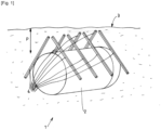
- FIG. 1 is a schematic and partial view illustrating an exemplary possible embodiment of the invention.
- the illustrated cryogenic fluid storage facility in particular for liquefied hydrogen, comprises a buried cryogenic tank 2.
- This cryogenic tank is configured to store a cryogenic fluid at a temperature preferably below 173K.
- This tank 2 is for example a double-walled tank whose inter-wall space is thermally insulated under vacuum.
- the tank 2 is buried directly underground with a depth P determined below the surface of the ground 3.
- buried directly is meant a burial without an enclosure or vault separating the tank from the earth (or sand or other) in which it is buried. That is to say that the external surface of the tank 2 can be in direct contact with the ground which surrounds it (or via an envelope, for example a flexible protective envelope).
- tank 2 is buried at a depth P of between 50cm and 10m, for example a depth of between 1 and 3m.
- the installation 1 comprises at least one heat transfer element 4 having a thermal conductivity greater than 10 W/mK and buried in the ground with a first end located between the upper end of the tank 2 and the surface of the ground and a second end located in a separate zone around the tank 2.
- the second end is located at a depth corresponding to the depth of half the height of the tank 2.
- the second end of the transfer element 4 is located at a depth in the ground which is greater than the depth of the first end.
- This configuration allows the dissipation of cold from the cold zone that may be located between the top of a buried tank and the ground, using an element composed of a material with higher thermal conductivity compared to the conductivity of a surrounding dry ground.
- This configuration reduces or eliminates the aforementioned drawbacks by homogenizing the temperature field around the buried tank 2.
- the heat transfer element 4 may be composed, for example, of aluminum (thermal conductivity 200 W/m.K), copper (thermal conductivity 350 W/m.K), steel (thermal conductivity 50 W/m.K) or other material having a conductivity greater than that of dry earth (thermal conductivity of the order of 0.75 W/m.K).
- the heat transfer element comprises several beams 4. More precisely, the installation 1 comprises a set of beams 4 made of a material with high thermal conductivity (aluminum, copper, etc.) buried in the upper part of the tank.
- a material with high thermal conductivity aluminum, copper, etc.
- the cryogenic tank 2 may be of the horizontal type, that is to say cylindrical in shape with a circular section and whose longitudinal axis is horizontal.
- the beams 4 are distributed along the longitudinal axis of the tank 2. As illustrated, the beams 4 may be arranged perpendicular to a tangent to the surface of the tank 2. In such an arrangement, the beams 4 may be perpendicular to the temperature lines of the cold zone. For example, these beams 4 may be spaced longitudinally from 5 cm to 200 cm. Their spacing is in particular designed to allow water flows to pass through. Heat dissipation is then achieved by simple thermal conduction: the cold from the upper pocket of the ground is thus evacuated towards the hot zones, on the sides around the tank 2.
- These beams or bars 4 may have a solid or hollow, square or circular or other section. These beams 4 may be installed directly in contact with the ground to favor thermal contact, during the filling of a pit, for example with sand. The length and/or the section and the number of beams 4 may be sized according to the needs.
- all or part of these beams 4 may include branches to increase the exchange surface between the ground and the conductive element.
- the invention is not limited to this example.
- the beam(s) 4 may be replaced or supplemented by other heat transfer elements, for example; a heat transfer fluid circuit, solid or perforated plate(s), block(s), fabric(s), etc.
- two blocks (or "sheets") of thermally conductive material can be arranged in the same way as the two rows of beams 4 illustrated (one conductive block on each side of the tank 2). These blocks can be pierced with holes to avoid problems of water accumulation. A simple fabric of sufficient length could also be considered.
Landscapes
- Engineering & Computer Science (AREA)
- Mechanical Engineering (AREA)
- General Engineering & Computer Science (AREA)
- Physics & Mathematics (AREA)
- Thermal Sciences (AREA)
- Filling Or Discharging Of Gas Storage Vessels (AREA)
Description
- L'invention concerne une installation de stockage de fluide cryogénique.
-
JPS58214096A - L'invention concerne plus particulièrement une installation de stockage de fluide cryogénique, notamment d'hydrogène liquéfié, comprenant un réservoir cryogénique enfoui directement sous terre avec une profondeur déterminée sous la surface du sol.
- A l'heure actuelle, la vaste majorité des réservoirs dans les stations-services pour carburants fossiles liquides (essence/Diesel) sont enterrés, en contact direct avec la terre (c'est-à-dire en enfouissement direct).
- Pour des carburants "alternatifs" (gaz naturel, hydrogène), les solutions restent à l'heure actuelle non enterrées ou logées dans des enceintes ou caveaux.
- Il a été constaté que lors de l'enterrement direct d'un tel réservoir cryogénique dans le sol, dans certaines conditions, il peut se former une poche de froid entre le haut du réservoir et la surface du sol.
- Cet effet est le résultat de la combinaison de l'existence de températures faibles autour du réservoir et de la présence d'un écran thermique entre le flux provenant de la terre et la surface du réservoir. Cette poche de froid représente potentiellement un risque pour les personnes et équipements au niveau du sol. En effet ceci peut générer une zone locale de givre, de glace, une détérioration d'équipement (fissuration d'ouvrages de génie civil due à l'apparition de contraintes provoquées par le gonflement différentiel du sol en cas de gel de ce dernier par exemple).
- Un but de la présente invention est de pallier tout ou partie des inconvénients de l'art antérieur relevés ci-dessus.
- A cette fin, l'installation selon l'invention, par ailleurs conforme à la définition générique qu'en donne le préambule ci-dessus, est essentiellement caractérisée en ce qu'il comporte au moins un élément de transfert thermique ayant une conductivité thermique supérieure à 10 W/m.K et enfoui dans le sol avec une première extrémité située entre le réservoir et la surface du sol et une seconde extrémité située dans une zone latérale autour du réservoir.
- Par ailleurs, des modes de réalisation de l'invention peuvent comporter l'une ou plusieurs des caractéristiques suivantes :
- l'élément de transfert thermique comprend au moins l'un parmi : une poutre, une conduite fluidique de fluide caloporteur, une plaque, un bloc, un tissu,
- l'élément de transfert thermique est composé de l'un au moins des matériaux suivants : métal, alliage, aluminium, cuivre, acier (carbone et inox), zinc, laiton, nickel, fer, étain, bronze, carbone (en particulier fibre de carbone ou graphite ou graphène ou nanotubes de carbone),
- la seconde extrémité du au moins un élément de transfert est située à une profondeur dans le sol qui est supérieure à la profondeur de la première extrémité,
- la seconde extrémité du au moins un élément de transfert est située à une profondeur correspondant à la profondeur de la moitié de la hauteur du réservoir,
- le réservoir est enfoui à une profondeur comprise entre 50cm et 10m,
- le réservoir cryogénique est du type horizontal, c'est-à-dire de forme oblongue dont l'axe longitudinal est horizontal, l'installation comprenant au moins un élément de transfert réparti selon la direction longitudinale du réservoir.
- L'invention peut concerner également tout dispositif ou procédé alternatif comprenant toute combinaison des caractéristiques ci-dessus ou ci-dessous dans le cadre des revendications.
- D'autres particularités et avantages apparaîtront à la lecture de la description ci-après, faite en référence aux figures dans lesquelles :
- L'invention sera mieux comprise à la lecture de la description qui va suivre donnée uniquement à titre d'exemple et faite en se référant aux dessins annexés dans lesquels :
[Fig. 1 ] est une vue schématique et partielle illustrant un exemple de réalisation possible de de l'invention. - L'installation 1 de stockage de fluide cryogénique illustrée, notamment pour de l'hydrogène liquéfié, comprend un réservoir 2 cryogénique enterré. Ce réservoir de type cryogénique est configuré pour stocker un fluide cryogénique à une température de préférence inférieure à 173K. Ce réservoir 2 est par exemple un réservoir à double parois dont l'espace inter-parois est isolé thermiquement sous vide.
- Le réservoir 2 est enfoui directement sous terre avec une profondeur P déterminée sous la surface du sol 3. Par « enfoui directement » on désigne un enterrement sans enceinte ou caveau séparant le réservoir de la terre (ou sable ou autre) dans lequel il est enfoui. C'est-à-dire que la surface extérieure du réservoir 2 peut être en contact direct avec le sol qui l'entoure (ou via une enveloppe, par exemple une enveloppe de protection souple).
- Par exemple, le réservoir 2 est enfoui à une profondeur P comprise entre 50cm et 10m, par exemple une profondeur comprise entre 1 et 3m.
- Selon une particularité avantageuse, l'installation 1 comprend au moins un élément 4 de transfert thermique ayant une conductivité thermique supérieure à 10W/m.K et enfoui dans le sol avec une première extrémité située entre l'extrémité supérieure du réservoir 2 et la surface du sol et une seconde extrémité située dans une zone distincte autour du réservoir 2. Par exemple, la seconde extrémité est située à une profondeur correspondant à la profondeur de la moitié de la hauteur du réservoir 2.
- De préférence, la seconde extrémité de l'élément 4 de transfert est située à une profondeur dans le sol qui est supérieure à la profondeur de la première extrémité.
- Cette configuration permet la dissipation du froid de la zone de froid qui peut se trouver entre le haut d'un réservoir enterré et le sol, en utilisant un élément composé d'un matériau à conductivité thermique supérieure par rapport à la conductivité d'un sol sec environnant.
- Cette configuration diminue ou supprime les inconvénients précités en homogénéisant le champ de températures autour du réservoir 2 enterré.
- Ceci permet un enfouissement direct avec ses avantages (empreinte au sol, coût, analyse de risque...).
- L'élément 4 de transfert thermique peut être composé par exemple d'aluminium (conductivité thermique 200 W/m.K), cuivre (conductivité thermique 350 W/m.K), acier (conductivité thermique 50 W/m.K) ou autre notamment ayant une conductivité supérieure à celle de la terre sèche (conductivité thermique de l'ordre de 0.75 W/m.K).
- Dans l'exemple illustré, l'élément de transfert thermique comprend plusieurs poutres 4. Plus précisément, l'installation 1 comprend un ensemble de poutres 4 en matériau à forte conductivité thermique (aluminium, cuivre...) enfouies dans la partie supérieure du réservoir.
- Le réservoir 2 cryogénique peut être du type horizontal, c'est-à-dire de forme cylindrique à section circulaire et dont l'axe longitudinal est horizontal.
- Les poutres 4 sont réparties le long de l'axe longitudinal du réservoir 2. Comme illustré, les poutres 4 peuvent être disposées perpendiculairement à une tangente à la surface du réservoir 2. Dans un tel agencement, les poutres 4 peuvent être perpendiculaires aux lignes de température de la zone froide. Par exemple, ces poutres 4 peuvent être espacées longitudinalement de 5cm à 200cm. Leur espacement est en particulier prévu pour permettre de laisser passer des écoulements d'eau. La dissipation thermique se fait alors par simple conduction thermique: le froid de la poche supérieure du sol est ainsi évacué vers les zones chaudes, sur les côtés autour du réservoir 2.
- Ces poutres ou barres 4 peuvent avoir une section pleine ou creuse, carrée ou circulaire ou autre. Ces poutres 4 peuvent être installées directement en contact avec le sol pour privilégier le contact thermique, pendant le remplissage d'une fosse, par exemple avec du sable. La longueur et/ou la section et le nombre des poutres 4 peuvent être dimensionnés en fonction des besoins.
- De même, tout ou partie de ces poutres 4 peuvent comporter des ramifications pour démultiplier la surface d'échange entre le sol et l'élément conducteur.
- Bien entendu, l'invention n'est pas limitée à cet exemple. Ainsi, la ou les poutres 4 peuvent être remplacées ou suppléées par d'autres éléments de transfert thermique, par exemple ; un circuit de fluide caloporteur, plaque(s) pleine(s) ou ajourée(s), bloc(s), un tissu (s)...
- Par exemple, deux blocs (ou "nappes") en matériau conducteur thermique peuvent être disposés de la même façon que les deux rangées de poutres 4 illustrées (un bloc conducteur de chaque côté du réservoir 2). Ces blocs peuvent être percés de trous pour éviter les problématiques d'accumulation d'eau. Un simple tissu suffisamment long pourrait également être considéré.
- Dans cette description détaillée ci-dessus, les réalisations mentionnées sont des exemples. Bien que la description se réfère à un ou plusieurs modes de réalisation, cela ne signifie pas que les caractéristiques s'appliquent seulement à un seul mode de réalisation. De simples caractéristiques de différents modes de réalisation peuvent également être combinées et/ou interchangées pour fournir d'autres réalisations.
Claims (7)
- Installation de stockage de fluide cryogénique, notamment d'hydrogène liquéfié, comprenant un réservoir (2) cryogénique enfoui directement sous terre avec une profondeur (P) déterminée sous la surface du sol (3), caractérisée en ce qu'il comporte au moins un élément (4) de transfert thermique ayant une conductivité thermique supérieure à 10 W/m.K et enfoui dans le sol avec une première extrémité située entre le réservoir (2) et la surface du sol et une seconde extrémité située dans une zone latérale autour du réservoir (2).
- Installation selon la revendication 1, caractérisée en ce que l'élément (4) de transfert thermique comprend au moins l'un parmi : une poutre (4), une conduite fluidique de fluide caloporteur, une plaque, un bloc, un tissu.
- Installation selon la revendication 1 ou 2, caractérisée en ce que l'élément (4) de transfert thermique est composé de l'un au moins des matériaux suivants : métal, alliage, aluminium, cuivre, acier (carbone et inox), zinc, laiton, nickel, fer, étain, bronze, carbone (en particulier fibre de carbone ou graphite ou graphène ou nanotubes de carbone).
- Installation selon l'une quelconque des revendications 1 à 3, caractérisée en ce que la seconde extrémité du au moins un élément (4) de transfert est située à une profondeur dans le sol qui est supérieure à la profondeur de la première extrémité.
- Installation selon l'une quelconque des revendications 1 à 3, caractérisée en ce que la seconde extrémité du au moins un élément (4) de transfert est située à une profondeur correspondant à la profondeur de la moitié de la hauteur du réservoir (2).
- Installation selon l'une quelconque des revendications 1 à 5, caractérisée en ce que le réservoir est enfoui à une profondeur (P) comprise entre 50cm et 10m.
- Installation selon l'une quelconque des revendications 1 à 6, caractérisée en ce que le réservoir (2) cryogénique est du type horizontal, c'est-à-dire de forme oblongue dont l'axe longitudinal est horizontal, l'installation comprenant au moins un élément (4) de transfert réparti selon la direction longitudinale du réservoir (2)
Applications Claiming Priority (1)
| Application Number | Priority Date | Filing Date | Title |
|---|---|---|---|
| FR2203704A FR3134869B1 (fr) | 2022-04-21 | 2022-04-21 | Installation de stockage de fluide cryogénique |
Publications (2)
| Publication Number | Publication Date |
|---|---|
| EP4265957A1 EP4265957A1 (fr) | 2023-10-25 |
| EP4265957B1 true EP4265957B1 (fr) | 2024-10-16 |
Family
ID=82196519
Family Applications (1)
| Application Number | Title | Priority Date | Filing Date |
|---|---|---|---|
| EP23166460.8A Active EP4265957B1 (fr) | 2022-04-21 | 2023-04-04 | Installation de stockage de fluide cryogénique |
Country Status (7)
| Country | Link |
|---|---|
| US (1) | US20230341089A1 (fr) |
| EP (1) | EP4265957B1 (fr) |
| JP (1) | JP2023160788A (fr) |
| KR (1) | KR20230150206A (fr) |
| CN (1) | CN116928568A (fr) |
| CA (1) | CA3195021A1 (fr) |
| FR (1) | FR3134869B1 (fr) |
Family Cites Families (4)
| Publication number | Priority date | Publication date | Assignee | Title |
|---|---|---|---|---|
| JPS5911079B2 (ja) * | 1979-09-03 | 1984-03-13 | 東京瓦斯株式会社 | 地中埋設ヒ−タ−線の施設方法 |
| JPS58214096A (ja) * | 1982-06-04 | 1983-12-13 | Ohbayashigumi Ltd | 液化ガス貯蔵用地下タンク |
| FR2528811A1 (fr) * | 1982-06-17 | 1983-12-23 | Geostock | Procede et dispositif de stockage de gaz liquefie a basse temperature dans une cavite souterraine |
| DE10107187A1 (de) * | 2001-02-15 | 2002-08-29 | Linde Ag | Tankstelle für kryogene Medien |
-
2022
- 2022-04-21 FR FR2203704A patent/FR3134869B1/fr not_active Expired - Fee Related
-
2023
- 2023-04-04 EP EP23166460.8A patent/EP4265957B1/fr active Active
- 2023-04-04 CA CA3195021A patent/CA3195021A1/fr active Pending
- 2023-04-13 CN CN202310392653.8A patent/CN116928568A/zh active Pending
- 2023-04-18 KR KR1020230050482A patent/KR20230150206A/ko active Pending
- 2023-04-20 US US18/136,999 patent/US20230341089A1/en active Pending
- 2023-04-20 JP JP2023069063A patent/JP2023160788A/ja active Pending
Also Published As
| Publication number | Publication date |
|---|---|
| FR3134869B1 (fr) | 2024-03-08 |
| JP2023160788A (ja) | 2023-11-02 |
| CA3195021A1 (fr) | 2023-10-21 |
| EP4265957A1 (fr) | 2023-10-25 |
| CN116928568A (zh) | 2023-10-24 |
| FR3134869A1 (fr) | 2023-10-27 |
| KR20230150206A (ko) | 2023-10-30 |
| US20230341089A1 (en) | 2023-10-26 |
Similar Documents
| Publication | Publication Date | Title |
|---|---|---|
| EP3350501B1 (fr) | Réservoir de stockage de fluide liquéfié | |
| CA1239849A (fr) | Dispositif de protection contre le gel d'installations de stockage ou fourniture de liquide gelif notamment de l'eau | |
| FR2884905A1 (fr) | Sonde de captage de l'energie thermique du sol pour pompe a chaleur | |
| EP4265957B1 (fr) | Installation de stockage de fluide cryogénique | |
| CA2538097C (fr) | Dispositif d'espacement et de centrage perfectionne pour conduite rigide a double enveloppe a faible coefficient de transfert thermique | |
| EP3380794B1 (fr) | Échangeur géothermique fermé à haute température et haute pression pour une formation magmatique ou métamorphique | |
| EP3645934B1 (fr) | Station et procédé de remplissage de réservoirs de gaz sous pression | |
| EP3465030B1 (fr) | Dispositif cryogenique a echangeur compact | |
| EP4361492A1 (fr) | Dispositif de stockage de fluide cryogénique | |
| EP2480839B1 (fr) | Dispositif d'echangeur geothermique comprenant une enceinte destinee a etre enfouie dans un sous-sol terrestre et a contenir un echangeur geothermique | |
| EP1703610A1 (fr) | Structure de connection électrique pour élément supraconducteur | |
| FR2913487A1 (fr) | Amelioration aux echangeurs gaz/sol ou liquides/sol et installations de chauffage ou de climatisation utilisant de tels echangeurs ameliores. | |
| FR2997787A1 (fr) | Generateur nucleaire a radioisotope | |
| EP1772685A2 (fr) | Dispositif de contrôle-commande permettant la gestion des transferts de chaleur pour améliorer ou adapter la récupération de chaleur géothermique du sol dans un système de pompe à chaleur | |
| FR3163716A1 (fr) | Pompe à chaleur géothermique de surface et son procédé d’installation | |
| WO2008135649A1 (fr) | Procédé d'alimentation d'un moteur thermique, notamment de type diesel ou essence. | |
| EP4599198A1 (fr) | Dispositif de réfrigération à basse température | |
| WO2025056852A1 (fr) | Systeme et procede de stockage pour le stockage de fluides comprenant un dispositif de ventilation | |
| FR3072443A1 (fr) | Dispositif de stockage de fluide cryogenique | |
| FR3136272A1 (fr) | Caloduc géothermique | |
| WO2025061936A1 (fr) | Assemblage comprenant un systeme de refroidissement | |
| JPS5911079B2 (ja) | 地中埋設ヒ−タ−線の施設方法 | |
| FR2862741A1 (fr) | Conduite pour le transport de gaz naturel liquefie | |
| BE603775A (fr) | ||
| FR2551110A1 (fr) | Dispositif de protection contre le gel d'installations de stockage ou fourniture de liquide gelif, en particulier de l'eau |
Legal Events
| Date | Code | Title | Description |
|---|---|---|---|
| STAA | Information on the status of an ep patent application or granted ep patent |
Free format text: STATUS: THE APPLICATION HAS BEEN PUBLISHED |
|
| PUAI | Public reference made under article 153(3) epc to a published international application that has entered the european phase |
Free format text: ORIGINAL CODE: 0009012 |
|
| AK | Designated contracting states |
Kind code of ref document: A1 Designated state(s): AL AT BE BG CH CY CZ DE DK EE ES FI FR GB GR HR HU IE IS IT LI LT LU LV MC ME MK MT NL NO PL PT RO RS SE SI SK SM TR |
|
| STAA | Information on the status of an ep patent application or granted ep patent |
Free format text: STATUS: REQUEST FOR EXAMINATION WAS MADE |
|
| 17P | Request for examination filed |
Effective date: 20240425 |
|
| RBV | Designated contracting states (corrected) |
Designated state(s): AL AT BE BG CH CY CZ DE DK EE ES FI FR GB GR HR HU IE IS IT LI LT LU LV MC ME MK MT NL NO PL PT RO RS SE SI SK SM TR |
|
| GRAP | Despatch of communication of intention to grant a patent |
Free format text: ORIGINAL CODE: EPIDOSNIGR1 |
|
| GRAP | Despatch of communication of intention to grant a patent |
Free format text: ORIGINAL CODE: EPIDOSNIGR1 |
|
| STAA | Information on the status of an ep patent application or granted ep patent |
Free format text: STATUS: GRANT OF PATENT IS INTENDED |
|
| RIC1 | Information provided on ipc code assigned before grant |
Ipc: F17C 3/00 20060101AFI20240530BHEP |
|
| INTG | Intention to grant announced |
Effective date: 20240614 |
|
| RIN1 | Information on inventor provided before grant (corrected) |
Inventor name: POURBAIX, THOMES Inventor name: PETITPAS, GUILLAUME |
|
| GRAS | Grant fee paid |
Free format text: ORIGINAL CODE: EPIDOSNIGR3 |
|
| GRAA | (expected) grant |
Free format text: ORIGINAL CODE: 0009210 |
|
| STAA | Information on the status of an ep patent application or granted ep patent |
Free format text: STATUS: THE PATENT HAS BEEN GRANTED |
|
| AK | Designated contracting states |
Kind code of ref document: B1 Designated state(s): AL AT BE BG CH CY CZ DE DK EE ES FI FR GB GR HR HU IE IS IT LI LT LU LV MC ME MK MT NL NO PL PT RO RS SE SI SK SM TR |
|
| REG | Reference to a national code |
Ref country code: GB Ref legal event code: FG4D Free format text: NOT ENGLISH |
|
| REG | Reference to a national code |
Ref country code: CH Ref legal event code: EP |
|
| REG | Reference to a national code |
Ref country code: IE Ref legal event code: FG4D Free format text: LANGUAGE OF EP DOCUMENT: FRENCH |
|
| REG | Reference to a national code |
Ref country code: DE Ref legal event code: R096 Ref document number: 602023000733 Country of ref document: DE |
|
| REG | Reference to a national code |
Ref country code: LT Ref legal event code: MG9D |
|
| REG | Reference to a national code |
Ref country code: NL Ref legal event code: MP Effective date: 20241016 |
|
| REG | Reference to a national code |
Ref country code: AT Ref legal event code: MK05 Ref document number: 1733165 Country of ref document: AT Kind code of ref document: T Effective date: 20241016 |
|
| PG25 | Lapsed in a contracting state [announced via postgrant information from national office to epo] |
Ref country code: NL Free format text: LAPSE BECAUSE OF FAILURE TO SUBMIT A TRANSLATION OF THE DESCRIPTION OR TO PAY THE FEE WITHIN THE PRESCRIBED TIME-LIMIT Effective date: 20241016 |
|
| PG25 | Lapsed in a contracting state [announced via postgrant information from national office to epo] |
Ref country code: NL Free format text: LAPSE BECAUSE OF FAILURE TO SUBMIT A TRANSLATION OF THE DESCRIPTION OR TO PAY THE FEE WITHIN THE PRESCRIBED TIME-LIMIT Effective date: 20241016 |
|
| PG25 | Lapsed in a contracting state [announced via postgrant information from national office to epo] |
Ref country code: HR Free format text: LAPSE BECAUSE OF FAILURE TO SUBMIT A TRANSLATION OF THE DESCRIPTION OR TO PAY THE FEE WITHIN THE PRESCRIBED TIME-LIMIT Effective date: 20241016 Ref country code: IS Free format text: LAPSE BECAUSE OF FAILURE TO SUBMIT A TRANSLATION OF THE DESCRIPTION OR TO PAY THE FEE WITHIN THE PRESCRIBED TIME-LIMIT Effective date: 20250216 Ref country code: PT Free format text: LAPSE BECAUSE OF FAILURE TO SUBMIT A TRANSLATION OF THE DESCRIPTION OR TO PAY THE FEE WITHIN THE PRESCRIBED TIME-LIMIT Effective date: 20250217 |
|
| PG25 | Lapsed in a contracting state [announced via postgrant information from national office to epo] |
Ref country code: FI Free format text: LAPSE BECAUSE OF FAILURE TO SUBMIT A TRANSLATION OF THE DESCRIPTION OR TO PAY THE FEE WITHIN THE PRESCRIBED TIME-LIMIT Effective date: 20241016 |
|
| PG25 | Lapsed in a contracting state [announced via postgrant information from national office to epo] |
Ref country code: BG Free format text: LAPSE BECAUSE OF FAILURE TO SUBMIT A TRANSLATION OF THE DESCRIPTION OR TO PAY THE FEE WITHIN THE PRESCRIBED TIME-LIMIT Effective date: 20241016 |
|
| PG25 | Lapsed in a contracting state [announced via postgrant information from national office to epo] |
Ref country code: ES Free format text: LAPSE BECAUSE OF FAILURE TO SUBMIT A TRANSLATION OF THE DESCRIPTION OR TO PAY THE FEE WITHIN THE PRESCRIBED TIME-LIMIT Effective date: 20241016 |
|
| PG25 | Lapsed in a contracting state [announced via postgrant information from national office to epo] |
Ref country code: NO Free format text: LAPSE BECAUSE OF FAILURE TO SUBMIT A TRANSLATION OF THE DESCRIPTION OR TO PAY THE FEE WITHIN THE PRESCRIBED TIME-LIMIT Effective date: 20250116 |
|
| PG25 | Lapsed in a contracting state [announced via postgrant information from national office to epo] |
Ref country code: LV Free format text: LAPSE BECAUSE OF FAILURE TO SUBMIT A TRANSLATION OF THE DESCRIPTION OR TO PAY THE FEE WITHIN THE PRESCRIBED TIME-LIMIT Effective date: 20241016 Ref country code: AT Free format text: LAPSE BECAUSE OF FAILURE TO SUBMIT A TRANSLATION OF THE DESCRIPTION OR TO PAY THE FEE WITHIN THE PRESCRIBED TIME-LIMIT Effective date: 20241016 Ref country code: GR Free format text: LAPSE BECAUSE OF FAILURE TO SUBMIT A TRANSLATION OF THE DESCRIPTION OR TO PAY THE FEE WITHIN THE PRESCRIBED TIME-LIMIT Effective date: 20250117 |
|
| PG25 | Lapsed in a contracting state [announced via postgrant information from national office to epo] |
Ref country code: PL Free format text: LAPSE BECAUSE OF FAILURE TO SUBMIT A TRANSLATION OF THE DESCRIPTION OR TO PAY THE FEE WITHIN THE PRESCRIBED TIME-LIMIT Effective date: 20241016 |
|
| PG25 | Lapsed in a contracting state [announced via postgrant information from national office to epo] |
Ref country code: RS Free format text: LAPSE BECAUSE OF FAILURE TO SUBMIT A TRANSLATION OF THE DESCRIPTION OR TO PAY THE FEE WITHIN THE PRESCRIBED TIME-LIMIT Effective date: 20250116 |
|
| PG25 | Lapsed in a contracting state [announced via postgrant information from national office to epo] |
Ref country code: SM Free format text: LAPSE BECAUSE OF FAILURE TO SUBMIT A TRANSLATION OF THE DESCRIPTION OR TO PAY THE FEE WITHIN THE PRESCRIBED TIME-LIMIT Effective date: 20241016 |
|
| PG25 | Lapsed in a contracting state [announced via postgrant information from national office to epo] |
Ref country code: DK Free format text: LAPSE BECAUSE OF FAILURE TO SUBMIT A TRANSLATION OF THE DESCRIPTION OR TO PAY THE FEE WITHIN THE PRESCRIBED TIME-LIMIT Effective date: 20241016 |
|
| REG | Reference to a national code |
Ref country code: DE Ref legal event code: R097 Ref document number: 602023000733 Country of ref document: DE |
|
| PG25 | Lapsed in a contracting state [announced via postgrant information from national office to epo] |
Ref country code: EE Free format text: LAPSE BECAUSE OF FAILURE TO SUBMIT A TRANSLATION OF THE DESCRIPTION OR TO PAY THE FEE WITHIN THE PRESCRIBED TIME-LIMIT Effective date: 20241016 |
|
| PG25 | Lapsed in a contracting state [announced via postgrant information from national office to epo] |
Ref country code: RO Free format text: LAPSE BECAUSE OF FAILURE TO SUBMIT A TRANSLATION OF THE DESCRIPTION OR TO PAY THE FEE WITHIN THE PRESCRIBED TIME-LIMIT Effective date: 20241016 |
|
| PG25 | Lapsed in a contracting state [announced via postgrant information from national office to epo] |
Ref country code: SK Free format text: LAPSE BECAUSE OF FAILURE TO SUBMIT A TRANSLATION OF THE DESCRIPTION OR TO PAY THE FEE WITHIN THE PRESCRIBED TIME-LIMIT Effective date: 20241016 |
|
| PG25 | Lapsed in a contracting state [announced via postgrant information from national office to epo] |
Ref country code: CZ Free format text: LAPSE BECAUSE OF FAILURE TO SUBMIT A TRANSLATION OF THE DESCRIPTION OR TO PAY THE FEE WITHIN THE PRESCRIBED TIME-LIMIT Effective date: 20241016 |
|
| PG25 | Lapsed in a contracting state [announced via postgrant information from national office to epo] |
Ref country code: IT Free format text: LAPSE BECAUSE OF FAILURE TO SUBMIT A TRANSLATION OF THE DESCRIPTION OR TO PAY THE FEE WITHIN THE PRESCRIBED TIME-LIMIT Effective date: 20241016 |
|
| PLBE | No opposition filed within time limit |
Free format text: ORIGINAL CODE: 0009261 |
|
| STAA | Information on the status of an ep patent application or granted ep patent |
Free format text: STATUS: NO OPPOSITION FILED WITHIN TIME LIMIT |
|
| PG25 | Lapsed in a contracting state [announced via postgrant information from national office to epo] |
Ref country code: SE Free format text: LAPSE BECAUSE OF FAILURE TO SUBMIT A TRANSLATION OF THE DESCRIPTION OR TO PAY THE FEE WITHIN THE PRESCRIBED TIME-LIMIT Effective date: 20241016 |
|
| 26N | No opposition filed |
Effective date: 20250717 |
|
| REG | Reference to a national code |
Ref country code: DE Ref legal event code: R119 Ref document number: 602023000733 Country of ref document: DE |
|
| PG25 | Lapsed in a contracting state [announced via postgrant information from national office to epo] |
Ref country code: LU Free format text: LAPSE BECAUSE OF NON-PAYMENT OF DUE FEES Effective date: 20250404 |
|
| PG25 | Lapsed in a contracting state [announced via postgrant information from national office to epo] |
Ref country code: MC Free format text: LAPSE BECAUSE OF FAILURE TO SUBMIT A TRANSLATION OF THE DESCRIPTION OR TO PAY THE FEE WITHIN THE PRESCRIBED TIME-LIMIT Effective date: 20241016 |
|
| REG | Reference to a national code |
Ref country code: BE Ref legal event code: MM Effective date: 20250430 |
|
| PG25 | Lapsed in a contracting state [announced via postgrant information from national office to epo] |
Ref country code: DE Free format text: LAPSE BECAUSE OF NON-PAYMENT OF DUE FEES Effective date: 20251104 |
|
| PG25 | Lapsed in a contracting state [announced via postgrant information from national office to epo] |
Ref country code: FR Free format text: LAPSE BECAUSE OF NON-PAYMENT OF DUE FEES Effective date: 20250430 |
|
| PG25 | Lapsed in a contracting state [announced via postgrant information from national office to epo] |
Ref country code: BE Free format text: LAPSE BECAUSE OF NON-PAYMENT OF DUE FEES Effective date: 20250430 |
|
| PG25 | Lapsed in a contracting state [announced via postgrant information from national office to epo] |
Ref country code: IE Free format text: LAPSE BECAUSE OF NON-PAYMENT OF DUE FEES Effective date: 20250404 |